

Testiranje performansi IEC 61850 GOOSE poruka
Jedan od čestih zahteva za uređaje relejne zaštite je podrška za IEC 61850 standard. U okviru standarda predviđene su i poruke za brzu razmenu informacija između releja tzv. GOOSE (Generic object-oriented substation event). U pitanju su uglavnom trip, interlocking, breaker failure i slični signali. Vreme transfera ovih signala je kritično, njihovo kašnjenje može prouzrokovati neželjeno isključenje potrošača ili oštećenje opreme.
U ovom radu istražićemo koja softverska arhitektura je najpogodnija da se ostvare tražene performanse. Softver za slanje/prijem GOOSE poruka može se nalaziti u real time (RT) ili user space prostoru operativnog sistema. Razmotrićemo user space i RT implementacije na dve različite mikroprocesorske arhitekture – ARM9 i PowerPC.
Do degradacije performansi može doći iz 2 razloga:
- Zaštitna funkcija ima najviši prioritet. Najmanje 500 μs tokom svake milisekunde GOOSE task će biti uskraćen za procesorsko vreme.
- U slučaju čiste user-space implementacije operativni sistem će prekidati GOOSE task na potpuno nedeterministički način.
User Space Test
Za testiranje performansi GOOSE poruka u user space-u razvijeno je okruženje bazirano na ARM7 arhitekturi:
- ARM7 sa integrisanim Ethernet-om za slanje, prijem i time-stampovanje poruka.
- PC aplikacija za setovanje parametara i prikupljanje rezultata.

- Slika 1. Test konfiguracija za user space test
Suština testa je sledeća: ARM7 ploča lansira niz poruka i beleži odlazno vreme za svaku poruku. ARM9 i PowerPC ploče su podešene da odmah po prijemu GOOSE poruke odgovore sa identičnom porukom sa istim rednim brojem.
ARM7 ploča registruje odgovor i pomoću rednog broja uparuje poruku sa originalnom porukom i računa proteklo vreme.

- Slika 2. Analiza vremena
Na gornjoj slici može se videti analiza utrošenog vremena. A i B su zanemarljivi. Zbog prirode testa može se precizno meriti 2C+D ali ne možemo tačno znati koliko iznose C i D pojedinačno. No, u krajnjoj liniji to i nije bitno sa stanovišta standarda. Pogledajmo rezultate testa. ARM7 ploča lansira niz GOOSE poruka u razmaku od 100ms. Rezultati se mere i prikazuju u Excel-u.
Da bi rezultat bio što realniji uključena je prekostrujna zaštita. Na Y osi prikazano je vreme u milisekundama a na X osi redni broj GOOSE poruke.
")
Slika 3. ARM9 100ms (X osa – redni broj poruke, Y osa vreme transfera)
Vidimo da tokom 20 sekundi vreme odgovora osciluje oko 2 milisekunde. Sledeći korak je bio da se uključi još nekoliko zaštitnih funkcija tako da tokom 1 milisekunde zaštita troši 700 μs. Očekivano je da pri većem opterećenju GOOSE performanse opadnu.
To se zaista i dešava kao što možemo videti na sledećoj slici:
")
Slika 4. ARM9 100ms, 700μs (X osa – redni broj poruke, Y osa vreme transfera)
Vreme sada osciluje oko 7 milisekudi. Iako je očekivano da će performanse opasti, ipak je postignuti rezultat iznad očekivanja. 7 milisekundi je i dalje dovoljno za neke aplikacije. Ovo su rezultati sa ARM9 platformu. PowerPC platforma se pokazala nešto bolje, jer ima skoro 2 puta veću procesorsku snagu. Na sledeće 2 slike vidimo rezultate.
")
Slika 5. PowerPC 100ms (X osa – redni broj poruke, Y osa vreme transfera)
")
Slika 6. PowerPC 100ms, 700μs (X osa – redni broj poruke, Y osa vreme transfera)
Pri manjem opterećenju vreme osciluje oko 0.8 ms a pri većem oko 2.5 ms. Kao što vidimo izmerena vremena se kreću u okvirima koji nude solidan dijapazon primena. Na žalost ova vremena važe samo u slučaju da je GOOSE task jedini aktivni task. U slučaju postojanja drugih taskova – na primer disturbance recorder, event recorder, embedded web server, IEC 61850 MMS server itd… vremena postaju nepredvidiva i mogu ići i do 80ms, što je naravno neprihvatljivo.
Real Time Test

Slika 7. Test konfiguracija za real time test
Mada je real time GOOSE nešto teži za implementaciju, nudi neke značajne prednosti kako ćemo videti. Test okruženje za real time je značajno drugačije. Za testiranje je korišćen mrežni analizator. Program se može besplatno skinuti sa Interneta (1). Suština testa je sledeća: zaštitni relej je podešen da osluškuje poruke koje emituje laptop računar i da momentalno odgovori sa istom vrednošću dataseta koja je u dolaznoj poruci. Kada analiziramo niz poruka u mrežnom analizatoru doći ćemo do momenta kada relej i laptop emituju identičnu vrednost.
Vreme između momenta kada laptop počinje sa emitovanjem i momenta kada relej počne da emituje istu vrednost kao i laptop je traženo vreme.
Na sledećoj slici možemo videti rezultate prikazane u mrežnom analizatoru.

Slika 8. Ethereal mrežni analizator

Slika 9. Niz GOOSE poruka sa vremenima prijema, mrežnim adresama i oznakom protokola
Poruku broj 42 emituje laptop,a poruku 43 relejna zaštita. Ako oduzmemo vremena prijema: 3,757 – 3,753 = 4msec. Pri ponovljenim merenjima rezultat osciluje oko 4ms. Razlog za to je što su taskovi za slanje i prijem podešeni da se bude na svake 2 milisekunde.
Zaključak
Na prvi pogled real time i user space implementacije operišu u sličnim vremenskim okvirima. Ali, postoji ozbiljna razlika. Kod RT implementacije GOOSE task može da deli procesor sa proizvoljnim brojem ostalih taskova kao što je disturbance recorder i sl. Takva arhitektura u mnogome smanjuje krajnju cenu uređaja i daje korisniku više funkcionalnosti. U suprotnom bi GOOSE softver morao da obitava na zasebnom hardveru.
.
AUTOR STRUČNOG TEKSTA:
Veljko Milisavljević | ABS Control Systems, Srbija
![]()
![]()
.
Related articles
- Testing performances of IEC 61850 GOOSE messages
- IEC 61850 Standard In Details (1)
- Benefits Of IEC 61850
- IEC 61850 Standard In Details (2)
- Line Protection With Distance Relays
2,691 views

The Best Applications For VFDs
The most commonly used motor in building HVAC applications is the three-phase, induction motor, although some smaller applications may use a single-phase induction motor. VFDs can be applied to both.
While VFD controllers can be used with a range of applications, the ones that will produce the most significant benefits are those that require variable speed operation. For example, the flow rate produced by pumps serving building HVAC systems can be matched to the building load by using a VFD to vary the flow rate. Similarly, in systems that require a constant pressure be maintained regardless of the flow rate, such as in domestic hot and cold water systems, a VFD controlled by a pressure setpoint can maintain the pressure over most demand levels.
The majority of commercial and institutional HVAC systems use variable volume fan systems to distribute conditioned air. Most are controlled by a system of variable inlet vanes in the fan system and variable air volume boxes. As the load on the system decreases, the variable air volume boxes close down, increasing the static pressure in the system. The fan’s controller senses this increase and closes down its inlet vanes. While using this type of control system will reduce system fan energy requirements, it is not as efficient or as accurate as a VFD-based system.
Another candidate for VFD use is a variable refrigerant flow systems. Variable refrigerant flow systems connect one or more compressors to a common refrigerant supply system that feeds multiple evaporators. By piping refrigerant instead of using air ducts, the distribution energy requirements are greatly reduced. Because the load on the compressor is constantly changing based on the demand from the evaporators, a VFD can be used to control the operating speed of the compressor to match the load, reducing energy requirements under part-load conditions.
Additional VFD Applications
While the primary benefit of both of these VFD applications is energy savings, VFDs are well suited for use in other applications where energy conservation is of secondary importance. For example, VFDs can provide precise speed or torque control in some commercial applications.
Some specialized applications use dual fans or pumps. VFDs, with their precise speed control, can ensure that the two units are operated at the desired speed and do not end up fighting each other or having one unit carry more than its design load level.
Advances in technology have increased the number of loads that can be driven by the units. Today, units are available with voltage and current ratings that can match the majority of three-phase induction motors found in buildings. With 500 horsepower units or higher available, facility executives have installed them on large capacity centrifugal chillers where very large energy savings can be achieved.
One of the most significant changes that has taken place recently is that with the widespread acceptance of the units and the recognition of the energy and maintenance benefits, manufacturers are including VFD controls as part of their system in a number of applications. For example, manufacturers of centrifugal chillers offer VFD controls as an option on a number of their units. Similarly, manufacturers of domestic water booster pump systems also offer the controls as part of their system, providing users with better control strategies while reducing energy and maintenance costs.
A Few Cautions
When evaluating the installation of a VFD, facility executives should take into consideration a number of factors related to the specifics of the application. For example, most VFDs emit a series of pulses that are rapidly switched. These pulses can be reflected back from the motor terminals into the cable that connects the VFD to the motor. In applications where there is a long run between the motor and the VFD, these reflected pulses can produce voltages that exceed the line voltage, causing stresses in the cable and motor windings that could lead to insulation failure. While this effect is not very significant in motors that operate at 230 volts or less, it is a concern for those that operate at 480 volts or higher. For those applications, minimize the distance between the VFD and the motor, use cabling specifically designed for use with VFDs, and consider installing a filter specifically designed to reduce the impact of the reflected pulses.
Another factor to consider is the impact the VFD may have on the motor’s bearings. The pulses produced by the VFD can generate a voltage differential between the motor shaft and its casing. If this voltage is high enough, it can generate sparks in the bearings that erode their surfaces. This condition can also be avoided by using a cable designed specifically for use with VFDs.
.
SOURCE: facilitiesnet
.
Related articles
- The Benefits of VFDs In HVAC Systems
- Cost benefits of AC drives
- General about motors
- The Nature Of Reactive Energy
- Transformer Ratings
4,270 views

The Benefits of VFDs In HVAC Systems
One of the most successful energy management tools ever applied to building HVAC systems is the variable frequency drive (VFD). For more than 20 years, VFDs have successfully been installed on fan and pump motors in a range of variable load applications. Energy savings vary from 35 to 50 percent over conventional constant speed applications, resulting in a return on investment of six months to two years.
While the number of applications suitable for early generation drives was limited based on the horsepower of the motor, today’s drives can be installed in practically any HVAC application found in commercial and institutional buildings. Systems can be operated at higher voltages than those used by earlier generations, resulting in off the shelf systems for motors up to 500 horsepower.
Early generation systems also suffered from low power factor. Low power factor robs the facility of electrical distribution capacity and can result in cost penalties imposed by electrical utility companies. Today’s systems operate at a nearly constant power factor over the entire speed range of the motor.
Another problem that has been corrected by today’s systems is operational noise. As the output frequency of the drives decreased in response to the load, vibrations induced in the motor laminations generated noise that was easily transmitted through the motor mounts to the building interior. Today’s drives operate at higher frequencies, resulting in the associated noise being above the audible range.
And VFDs continue to evolve. From numerous system benefits to an increasing range of available applications, VFDs are proving to be ever more useful and powerful.
The Heart of VFDs
Most conventional building HVAC applications are designed to operate fans and pumps at a constant speed. Building loads, however, are anything but constant. In a conventional system, some form of mechanical throttling can be used to reduce water or air flow in the system. The drive motor, however, continues to operate at full speed, using nearly the same amount of energy regardless of the heating or cooling load on the system. While mechanical throttling can provide a good level of control, it is not very efficient. VFDs offer an effective and efficient alternative.
Three factors work together to improve operating efficiency with VFDs:
1. Operating at less than full load. Building systems are sized for peak load conditions. In typical applications, peak load conditions occur between 1 and 5 percent of the annual operating hours. This means that pump and fan motors are using more energy than necessary 95 to 99 percent of their operating hours.
2. Oversized system designs. Designing for peak load oversizes the system for most operating hours. This condition is further compounded by the practice of oversizing the system design to allow for underestimated and unexpected loads as well as future loads that might result from changes in how the building space is used.
3. Motor energy use is a function of speed. The most commonly used motor in building HVAC systems is the induction motor. With induction motors, the power drawn by the motor varies with the cube of the motor’s speed. This means that if the motor can be slowed by 25 percent of its normal operating speed, its energy use is reduced by nearly 60 percent. At a 50 percent reduction in speed, energy use is reduced by nearly 90 percent.
The installation of a VFD in an HVAC application addresses the inefficiencies introduced by the first two factors, while producing the energy savings made possible by the third. The VFD accomplishes this by converting 60 cycle line current to direct current, then to an output that varies in voltage and frequency based on the load placed on the system. As the system load decreases, the VFD’s controller reduces the motor’s operating speed so that the flow rate through the system meets but does not exceed the load requirements.
VFD Benefits
The most significant benefit to using a VFD is energy savings. By matching system capacity to the actual load throughout the entire year, major savings in system motor energy use are achieved.
Another benefit of the units is reduced wear and tear on the motors. When an induction motor is started, it draws a much higher current than during normal operation. This inrush current can be three to ten times the full-load operating current for the motor, generating both heat and stress in the motor’s windings and other components. In motors that start and stop frequently, this contributes to early motor failures.
In contrast, when a motor connected to a VFD is started, the VFD applies a very low frequency and low voltage to the motor. Both are gradually ramped up at a controlled rate to normal operating conditions, extending motor life.
VFDs also provide more precise levels of control of applications. For example, high-rise buildings use a booster pump system on the domestic water supply to maintain adequate water pressure at all levels within the building. Conventional pump controls in this type of application can maintain the pressure within a certain range, but a VFD-based system can maintain more precise control over a wider range of flow rates, while reducing energy requirements and pump wear.
.
SOURCE: facilitiesnet
.
Related articles
- Cost benefits of AC drives
- The Best Applications For VFDs
- General about motors
- The Power Factor
- Reduction In The Cost Of Electricity
3,807 views

Siemens technical publication | Loss Of Vacuum
If a vacuum interrupter should lose vacuum, several operating situations should be considered:
1. With contacts open
2. When closing
3. When closed and operating normally
4. When opening and interrupting normal current
5. When opening and interrupting a fault.
Cases 1, 2 and 3 are relatively straightforward. Generally, the system sees no impact from loss of vacuum in such a situation. Cases 4 and 5, however, require further discussion. Suppose there is a feeder circuit breaker with a vacuum interrupter on phase 3 that has lost vacuum. If the load being served by the failed interrupter is a deltaconnected (ungrounded) load, a switching operation would not result in a failure. Essentially, nothing would happen. The two good phases (phase 1 and phase 2, in this example) would be able to clear the circuit, and current in the failed interrupter (phase 3) would cease.
The alternative case of a grounded load is a different situation. In this case, interruption in the two good phases (phase 1 and phase 2) would not cause current to stop flowing in phase 3, and the arc would continue to exist in phase 3. With nothing to stop it, this current would continue until some backup protection operated. The result, of course, would be destruction of the interrupter.
Since the predominant usage of circuit breakers in the 5-15 kV range is on grounded circuits, we investigated the impact of a failed interrupter some years ago in the test lab. We intentionally caused an interrupter to lose vacuum by opening the tube to the atmosphere. We then subjected the circuit breaker to a full short circuit interruption. As predicted,
the “flat” interrupter did not successfully clear the affected phase, and the “flat” interrupter was destroyed. The laboratory backup breaker cleared the fault. Following the test, the circuit breaker was removed from the switchgear cell. It was very sooty, but mechanically intact. The soot was cleaned from the circuit breaker and the switchgear cell, the faulty interrupter was replaced, and the circuit breaker was re-inserted in the cell. Further short circuit interruption tests were conducted the same day on the circuit breaker.
Field experience in the years since that test was conducted supports the information gained in the laboratory experiment. One of our customers, a large chemical operation, encountered separate failures (one with an air magnetic circuit breaker and one with a vacuum circuit breaker) on a particular circuit configuration. Two different installations, in different countries, were involved. They shared a common circuit configuration and failure mode. The circuit configuration, a tie circuit in which the sources on each side of the circuit
breaker were not in synchronism, imposed approximately double rated voltage across the contact gap, which caused the circuit breaker to fail. Since these failures resulted from application in violation of the guidelines of the ANSI standards, and greatly in excess of the design ratings of the circuit breakers, they are not indicative of a design
problem with the equipment.
However, the damage that resulted from the failures is of interest. In the case of the air magnetic circuit breaker, the unit housing the failed circuit breaker was destroyed, and the adjacent switchgear units on either side were damaged extensively, requiring significant rebuilding. The air magnetic circuit breaker was a total loss. In the case of the vacuum circuit breaker, the failure was considerably less violent. The vacuum interrupters were replaced, and the arc by-products (soot) cleaned from both the circuit breaker and the compartment. The unit was put back into service. Our test experience in the laboratory, where we routinely explore the limits of interrupter performance, also supports these results.
More recently, several tests were performed in our high-power test laboratory to compare the results of attempted interruptions with “leaky” vacuum interrupters. A small hole (approximately 1/8” diameter) was drilled in the interrupter housing, to simulate a vacuum interrupter that had lost vacuum.
The results of these tests were very interesting:
- One pole of a vacuum circuit breaker was subjected to an attempted interruption of 1310 A (rated continuous current = 1250 A). The current was allowed to flow in the “failed” interrupter for 2.06 seconds, at which point the laboratory breaker interrupted. No parts of the “failed” circuit breaker or the interrupter flew off, nor did the circuit breaker explode. The paint on the exterior of the interrupter arcing chamber peeled off. The remainder of the circuit breaker was undamaged.
. - A second pole of the same vacuum circuit breaker was subjected to an attempted interruption of 25 kA (rated interrupting current = 25 kA), for an arc-duration of 0.60 seconds, with the laboratory breaker interrupting the current at that time. The arc burned a hole in the side of the arc chamber. The circuit breaker did not explode, nor did parts of the circuit breaker fly off. Glowing particles were ejected from the hole in the arcing chamber. None of the mechanical components or other interrupters were damaged. Essentially, all damage was confined to the failed interrupter.
Our experience suggests rather strongly that the effects of a vacuum interrupter failure on the equipment are very minor, compared to the impact of failures with alternative interruption technologies. But the real question is not what the results of a failure might be, but rather, what is the likelihood of a failure? The failure rate of Siemens vacuum interrupters is so low that loss of vacuum is no longer a significant concern. In the early 1960s with early vacuum interrupters, it was a big problem. A vacuum interrupter is constructed with all connections between dissimilar materials made by brazing or welding. No organic materials are used. In the early years, many hand-production techniques were used, especially when borosilicate glass was used for the insulating envelope, as it could not tolerate high temperatures. Today, machine welding and batch induction furnace brazing are employed with extremely tight process control. The only moving part inside the interrupter is the copper contact, which is connected to the interrupter end plate with a welded stainless steel bellows. Since the bellows is welded to both the contact and the interrupter end plate, the failure rate of this moving connection is extremely low. This accounts for the
extremely high reliability of Siemens vacuum interrupters today.
In fact, the MTTF (mean time to failure) of Siemens power vacuum interrupters has now reached 24,000 years (as of October 1991). Questions raised by customers regarding loss of vacuum were legitimate concerns in the 1960s, when the use of vacuum interrupters for power applications was in its infancy. At that time, vacuum interrupters suffered from frequent leaks, and surges were a problem. There was only one firm that offered vacuum circuit breakers then, and reports suggest that they had many problems. We entered the vacuum circuit breaker market in 1974, using Allis-Chalmers’ technology and copper-bismuth contact materials. In the early 1980′s, after becoming part of the worldwide Siemens organization, we were able to convert our vacuum designs to use Siemens vacuum interrupters, which had been introduced in Europe in the mid-1970s. Thus, when we adopted the Siemens vacuum interrupters in the U.S., they already had a very well established field performance record.
The principle conceptual differences in the modern Siemens vacuum interrupters from the early 1960s designs lies in contact material and process control. Surge phenomena are more difficult to deal with when copper-bismuth contacts are used than with today’s chromecopper contacts. Similarly, leaks were harder to control with vacuum interrupters built largely by hand than with today’s units. Today, great attention is paid to process control and elimination of the human factor (variability) in manufacture. The result is that the Siemens vacuum interrupters today can be expected to have a long service life and to impose dielectric stress on load equipment that is not significantly different from the stresses associated with traditional air magnetic or oil circuit breakers.
.
Published by: SIEMENS AG
.
Related articles
- Arc-resistant low voltage switchgear
- Standard IEC 60947-2
- Maintenance Of Meduim Voltage Circuit Breakers
- Maintenance Of Low Voltage Circuit Breakers
- Comparison Between Vacuum and SF6 Circuit Breaker
6,261 views
")
IEC 61850 Standard In Details (part 2)
Continued from first part of article IEC 61850 Standard In Details (1)
Services provided by ACSI include querying object set, getting/setting data values, controlling system objects, report manipulation, log manipulation, and other services like file upload/download. Table 3 gives a list of ACSI services defined in the IEC 61850 standard.
All ACSI services are requested by applications and responded by servers. In order to request a service in a server, an application must first establish a valid two-party application association (TPAA) with the server. The TPAA maintains the session states and provides a virtual view of the server to the application.
A typical interaction procedure between an application A and a server S goes as follows:
- A establishes a TCP connection with S;
- A “logs in” to S by requesting the Associate service from S, providing authentication related information as parameters;
- S validates the information provided by A and creates a TPAA object, which provides a virtual view of S to A;
- A requests subsequent services while S processes the requests and responses with appropriate responses defined in the IEC 61850 standard;
- A issues a Release request to S ; 6. S reclaims the TPAA of A and ends the session.
The virtual view of server provided by a TPAA enforces the access control policies set forth by the server. This virtual view defines which objects in the server are visible and accessible to the application and what kinds of service of those objects are accessible from the application. The concept of virtual view is very flexible and the IEC 61850 standard does not place any restriction on the access control policies of the server. One possible and relatively simple access control is the world-group-owner access control for files used in many UNIX systems.

Table 3: ACSI services
Reporting and logging
The IEC 61850 standard provides an efficient mechanism called reporting for applications to track changes to the subscribed system objects. Instead of polling the data attribute values periodically, applications can group the interesting data attributes into a data set, and require the logical node hosting this data set report any changes to the members of this data set. Theoretically a data set can contain data objects/data attributes from different logical nodes, but data sets for reporting usually contain only the data objects/data attributes in the same logical node.
The procedure of report generation and transmission is under the control of an information block called report control block (RCB). A RCB maintains the necessary information to generate a report like which fields should be included in the report, on what events a report should be generated, the sequence number of the current report, whether this RCB is enabled, etc..
A typical report generation and transmission procedure is described as follows:
- client application creates a data set containing all the data objects and data attributes it concerns;
- client sets the parameters in a RCB, specifies the aforementioned data set as the source of the reports (this step is called to “subscribe to a data set”) and enables this RCB;
- on any change to any member of the data set, the logical node tests this change against the event list of the RCB, and issues an internal event if any event in the list gets matched;
- on receiving the internal event, the RCB stores this event for later sending;
- if the condition of sending the report is satisfied, the logical node collects necessary data, generates the report and sends it out to the client via the association under the direction of the parameters in the RCB.
Reports can be sent by either two-party application association (TPAA) or multi-party application association (MPAA). TPAA is the association that can serve only one client while MPAA can serve more than one client simultaneously. Reports generated on the request of the Report service is sent by TPAA, whereas other reports are sent by MPAA. Reporting uses a publisher/subscriber mechanism: for every client, the server must assign an individual RCB to handle the report generation and transmission.
Logging is a mechanism to record the device events. Logs are stored in the server and hosted by the corresponding logical device. Unlike reporting, every time a device event is triggered, the logical device merely saves a log entry into the log database for later inquiries.
Generic substation event
Besides reporting, the IEC 61850 standard defines generic substation event (GSE) as another means for applications to monitor changes to the data objects/data attributes. GSE is designed for fast delivering notification of system object changes. There are two kinds of GSE, generic object-oriented substation events (GOOSE) and generic substation state event (GSSE). GOOSE is used to exchange a wide range of common data while GSSE is used to convey state change information. The GSE mechanism shares a lot of similarities with reporting, with the major difference that GSE is designed for fast information exchange inside a substation while reporting is mainly used for sending notification from the server side to remote control centers or browsers.
Since real-time performance is critical for GSE messages, the message format and communication stack for GSE transmission is very different from those for reporting. GSE messages are transmitted in binary format, which provides shorter message body and higher message encoding/decoding speed. In stead of using TCP or UDP as the underlying transport layer, GSSE uses its specific transport layer while GOOSE messages are sent to the Ethernet link layer directly without going through any transport layer or network layer.
GSE also utilizes a publisher/subscriber mechanism to transmit the messages. This mechanism is implemented by the Ethernet multicast feature: the publisher sends the GSE message to a specific multi-cast MAC address and the subscribers pick up messages sent to this address, put them into their local buffer for the local applications to consume.
Communication network
The IEC 61850 standard defines a distributed system consisting of interacting logical nodes, which are connected by logical connections. However, in order for this distributed system to work correctly and intelligently, there must be some intelligent components inside this network. It is not hard to see that applications play this role. An interesting question is how to integrate applications into the interacting logical node network. We try to answer this question by starting from the simple ACSI server-application network.
Figure 5 shows such a server-application network. Clearly, each server may serve several applications and vice versa. The dotted lines in Figure 5 refer to the communication channels for reports and GSE messages. Although there are no restrictions about the relationship between report subscribers and report publishers, it is not true for GSE messages. The design of GSE has physical concerns. GSE messages are sent from one IED to another, thus the subscribers and the publishers should not reside in the same IED.
To make things more clear, let us transform Figure 5 into Figure 6, which shows the communication between applications and logical nodes (we hid the communication to server and logical devices). At this point, we can clearly see that logical connections between logical nodes are actually a mixture of several kinds of connections: when a logical node sends a message to another logical node, it is virtually sending reports/GSE messages to the relevant applications; after necessary processing of the reports/GSE messages, the applications issue relevant requests to the other logical node, and vice versa.
Thus we can deploy the application logic to the relevant logical nodes and get Figure 7 by abstracting away the applications. Being aware of this abstraction is important for both implementation and simulation of the IEC 61850 protocol.

Figure 5: Server-Application network
.

Figure 6: Logical node-application network
.

Figure 7: Logical node network
Simulating the IEC 61850
In this section, we talk about the design and implementation of a simulator of the IEC 61850 standard. Due to the challenges listed in Section 2.1, simulating the entire protocol is very difficult. Since the goal of our simulation is to inspect possible security vulnerabilities in the protocol, we refined the protocol to a version containing only data gathering/setting related ACSI services and reporting services. Furthermore we simplified the data model by abstracting various data attribute types to string and discarding the concept of functional constraint. Currently, features of the IEC 61850 protocol supported by our simulation model include two-party application association, data attribute, data object, data set, logical node, logical device, server, ACSI services, reporting and unbuffered report control block.
Design and implementation of the simulator
In order to inspect the IEC 61850 standard, we need a tool to simulate the protocol. Demo software of the protocol exists [10]. However, they are mostly provided by the IED manufacturer and are not freely available for research purposes. Kostic et al. proposed an implementation of ACSI [6]. The work of Kostic et al. focuses on implementing a set of application programming interface for device and application development, while we would like to build our own simulation tool for further study on the IEC 61850, especially on network security issues.
Our simulator consists of about 3,500 lines of Java code. Its components are divided into three major categories: the data model, internal message representation and the service model. Figure 8 shows the architecture of the simulator.

Figure 8: The IEC 61850 simulator architecture
Data model
The internal data model in the simulator is the same as the one defined in the IEC 61850 standard. All the IEC 61850 objects are instances of the I6Object class and are organized as a tree as shown in Figure 9. I6Object class provides a collection of services to manage the objects.

Figure 9: The IEC 61850 simulator data model
Table 4 lists some frequently used services.

Table 4: Major services of I6Object
The lock and unlock services are necessary because the IEC 61850 standard allows multiple accesses to the same object simultaneously. One would resolve this problem by sequentializing all the received requests, but since reports could be generated at the time when the related data objects are being updated, synchronization mechanism is still needed. One could implement lock as locking the whole object tree, but this would lead to severe performance problems, even dead locks. Our solution is to lock the whole subtree dominated by the locked object and mark all the ancestor nodes of that object as partly locked so that these ancestor nodes cannot be locked by other Associations.
Each kind of the IEC 61850 objects are implemented as a subclass of I6Object. These subclasses provide templates to define the desired specialized classes. For example, in order to create a specialized logical device class, one just need to derive a subclass from the LDevice class and use the declareLN method to declare the member logical nodes in the configure function.
Using the IEC 61850 data model as the internal data model has two advantages: on the one hand, there is no need to map the internal data representation to the IEC 61850 data model in such an approach; on the other hand, we can deploy the implementation of the ACSI services to the relevant object classes thus achieve a simple object-oriented approach. However, our simulation experience shows such a simple internal data representation might not be a good choice because of the following two reasons:
- The data model defined by the IEC 61850 is unnecessarily structured as a tree. Functional constraints present another view of data attributes in a logical node, breaking the tree structure maintained by data objects.
- Some ACSI services are not easy to deploy to the specific object classes. One example is the CreateDataSet service, which should be implemented by the LogicalNode class or the Association class instead of the DataSet class.
To maintain the tree structure, one can implement functional constraints as implicit data sets, and redirect the service requests to the appropriate object class using a dispatcher in the Association class.

Figure 10: Internal message of the simulator
Instead of maintaining an internal representation, we recommend an other approach: using a lightweight database system as the backend storage support. This approach provides several benefits:
- A database system provides the most flexible and easiest way to maintain the appropriate tables and views. A database system incorporates all the necessary services to operate on the object tables, reducing the complexity of maintaining an internal data representation.
- A database system supports exclusive object accesses, so the engineer does not need to explicitly perform lock and unlock operations.
- Database systems are usually optimized for data storage and access, thus the database system approach can give comparable real-time performance against the internal data representation approach.
Message representation
Messages are used in two cases: as internal events and as requests/responses of ACSI services. Although the IEC 61850 standard defines manufacturing message specification (MMS) as its representation format for information exchange, we would like to use another information representation format because on the one hand, MMS is relatively complicated and on the other hand, the details about the MMS standard is not freely available.
Messages in our simulator are represented as attributed trees. There are three kinds of tree nodes (Figure 10): SimpleMsg, ComplexMsg and ListMsg. A SimpleMsg node is a leaf node containing a string value, which is used to represent a value. A ComplexMsg node is a node containing a collection of named attributes, the values of which are also nodes.

Figure 11: Implementation of the ACSI service
A ListMsg node is a node that represents a list, with each member also a node. Our message tree is virtually a simplified version of a XML DOM tree. Using such kind of message representation, we can easily pass the internal events and service parameters/responses among different internal objects.
Service model
Figure 11 shows the internal architecture of the implementation of the ACSI services on the server side. Each active association is equipped with an instance of AssocAPI. AssocAPI provides the basic ACSI interface for an association instance. On receiving the application requests, the association instance invokes relevant services provided by AssocAPI to complete the tasks. AssocAPI is supported both by the underlying kernel services which provides the basic functions to complete the ACSI service requests, and by the communication utilities, which talks to J-Sim [11], a network simulator.
Instead of delivering the reports using multi-party application associations, we deliver them to the applications using the corresponding two-party application associations. The reporting procedure is rather straight-forward: when the value of a data attribute is changed or updated, we check whether this operation satisfies the trigger condition. If the trigger condition is met, the data attribute issues an internal event to all the data sets marking it as a member and those data sets will forward the internal event to the active report control blocks, which generate the reports and send them to the subscribing applications. For the sake of simplification, we assume the members of a data set are all data attributes in our simulation.
.
SOURCE:
- Understanding and Simulating the IEC 61850 Standard by Yingyi Liang & Roy H. Campbell, Department of Computer Science University of Illinois at Urbana-Champaign
.
Related articles
- IEC 61850 Standard In Details (1)
- Benefits Of IEC 61850
- KNX Architecture
- Testing performances of IEC 61850 GOOSE messages
- Testiranje performansi IEC 61850 GOOSE poruka
15,276 views

Busbar Technical Specification
Copper busbars are normally part of a larger generation or transmission system. The continuous rating of the main components such as generators, transformers, rectifiers, etc., therefore determine the nominal current carried by the busbars but in most power systems a one to four second short-circuit current has to be accommodated.
The value of these currents is calculated from the inductive reactances of the power system components and gives rise to different maximum short-circuit currents in the various system sections.
.
Performance under Short-circuit Conditions
Busbar trunking systems to BS EN 60439-2 are designed to withstand the effects of short-circuit currents resulting from a fault at any load point in the system, e.g. at a tap off point or at the end of a feeder run.
.
Rating under Short-circuit Conditions
The withstand ability will be expressed in one or more of the following ways:
- short-time withstand rating (current and time)
- peak current withstand rating
- conditional short-circuit rating when protected by a short-circuit protective device (s.c.p.d.)
These ratings are explained in more detail:
1. Short-time Withstand Rating
This is an expression of the value of rms current that the system can withstand for a specified period of time without being adversely affected such as to prevent further service. Typically the period of time associated with a short-circuit fault current will be 1 second, however, other time periods may be applicable.
The rated value of current may be anywhere from about 10kA up to 50kA or more according to the construction and thermal rating of the system.
2. Peak Current Withstand Rating
This defines the peak current, occurring virtually instantaneously, that the system can withstand, this being the value that exerts the maximum stress on the supporting insulation.
In an A.C. system rated in terms of short-time withstand current the peak current rating must be at least equal to the peak current produced by the natural asymmetry occurring at the initiation of a fault current in an inductive circuit. This peak is dependent on the power-factor of the circuit under fault conditions and can exceed the value of the steady state fault current by a factor of up to 2.2 times.
3. Conditional Short-circuit Rating
Short-circuit protective devices (s.c.p.ds) are commonly current-limiting devices; that is they are able to respond to a fault current within the first few milliseconds and prevent the current rising to its prospective peak value. This applies to HRC fuses and many circuit breakers in the instantaneous tripping mode. Advantage is taken of these current limiting properties in the rating of busbar trunking for high prospective fault levels. The condition is that the specified s.c.p.d. (fuse or circuit breaker) is installed up stream of the trunking. Each of the ratings above takes into account the two major effects of a fault current, these being heat and electromagnetic force.
The heating effect needs to be limited to avoid damage to supporting insulation. The electromagnetic effect produces forces between the busbars which stress the supporting mechanical structure, including vibrational forces on A.C. The only way to verify the quoted ratings satisfactorily is by means of type tests to the British Standard.
.
Type Testing
Busbar trunking systems are tested in accordance with BS EN 60439-2 to establish one or more of the short circuit withstand ratings defined above. In the case of short-time rating the specified current is applied for the quoted time. A separate test may be required to establish the peak withstand current if the quoted value is not obtained during the short-time test. In the case of a conditional rating with a specified s.c.p.d. the test is conducted with the full prospective current value at the trunking feeder unit and not less than 105% rated voltage, since the s.c.p.d. (fuse or circuit breaker) will be voltage dependent in terms of let through energy.
.
Application
It is necessary for the system designer to determine the prospective fault current at every relevant point in the installation by calculation, measurement or based on information provided e.g. by the supply authority. The method for this is well established, in general terms being the source voltage divided by the circuit impedance to each point. The designer will then select protective devices at each point where a circuit change occurs e.g. between a feeder and a distribution run of a lower current rating. The device selected must operate within the limits of the busbar trunking short-circuit withstand.
The time delay settings of any circuit breaker must be within the specified short time quoted for the prospective fault current. Any s.c.p.d. used against a conditional short-circuit rating must have energy limitation not exceeding that of the quoted s.c.p.d. For preference the s.c.p.d. recommended by the trunking manufacturer should be used.
.
Voltage Drop
The requirements for voltage-drop are given in BS 7671: Regulation 525-01-02. For busbar trunking systems the method of calculating voltage drop is given in BS EN 60439-2 from which the following guidance notes have been prepared.
Voltage Drop
Figures for voltage drop for busbar trunking systems are given in the manufacturer’s literature.
The figures are expressed in volts or milli-volts per metre or 100 metres, allowing a simple calculation for a given length of run.
The figures are usually given as line-to-line voltage drop for a 3 phase balanced load.
The figures take into account resistance to joints and temperature of conductors and assume the system is fully loaded.
Standard Data
BS EN 60439-2 requires the manufacturer to provide the following data for the purposes of calculation, where necessary:
R20 the mean ohmic resistance of the system, unloaded, at 20ºC per metre per phase
X the mean reactance of the system, per metre per phase
For systems rated over 630A:
RT the mean ohmic resistance when loaded at rated current per metre per phase
Application
In general the voltage drop figures provided by the manufacturer are used directly to establish the total voltage drop on a given system; however this will give a pessimistic result in the majority of cases.
Where a more precise calculation is required (e.g. for a very long run or where the voltage level is more critical) advantage may be taken of the basic data to obtain a more exact figure.
- Resistance – the actual current is usually lower than the rated current and hence the resistance of the conductors will be lower due to the reduced operating temperature.
.
Rx = R20 [1+0.004(Tc - 20)] ohms/metre and Tc is approximately Ta + Trwhere Rx is the actual conductor resistance
Ta is the ambient temperature
Tr is the full load temperature rise in ºC (assume say 55ºC)
- Power factor – the load power factor will influence the voltage drop according to the resistance and reactance of the busbar trunking itself.
The voltage drop line-to-line ( Δv) is calculated as follows:Δv = √ 3 I (R x cos Φ + X sin Φ) volts/metre
where I is the load current
Rx is the actual conductor resistance (Ω/m)
X is the conductor reactance (Ω/m)
Cos Φ is the load power factor
sin Φ = sin (cos-1 Φ )
- Distributed Load – where the load is tapped off the busbar trunking along its length this may also be taken into account by calculating the voltage drop for each section. As a rule of thumb the full load voltage drop may be divided by 2 to give the approximate voltage drop at the end of a system with distributed load.
. - Frequency – the manufacturers data will generally give reactance (X) at 50Hz for mains supply in the UK. At any other frequency the reactance should be re-calculated.
.
Xf = x F/50
.
where Xf is the reactance at frequency F in Hz
.
Source: Siemens Barduct Busbar Specification
.
Related articles
- Line Protection With Distance Relays
- Short Circuit Parameters in Low Voltage AC Circuits
- Arc-resistant low voltage switchgear
- General about motors
- The Power Factor

Dry-Type disc wound transformers in MV applications
Medium voltage, dry-type transformers may have their high voltage windings constructed using either the layer winding technique or the disc winding technique.
Both winding techniques provide the same result in terms of electrical performance parameters, i.e. turns ratio, impedance etc.
However, the use of transformers employing disc wound high voltage windings can result in increased reliability and therefore reduced downtime.
Introduction
The basic purpose of a transformer is to convert electricity at one voltage to electricity at another voltage, either of higher or lower value. In order to achieve this voltage conversion, coils are wound on a laminated silicon steel core which provides a path for the magnetic flux. The coils comprise a number of turns of conductor, either copper or aluminum, wound as two electrically separate windings, called the primary winding and the secondary winding. The primary winding is connected to the source of voltage while the secondary winding is connected to the load. The ratio of primary to secondary turns is the same as the required ratio of primary to secondary voltages.
The turns of conductor forming the primary and secondary windings must be insulated from one another, while the primary winding must be insulated from the secondary winding and both the primary and secondary windings must be insulated from ground. The insulation of turns and windings is collectively called the insulation system of the transformer. The insulation system must be designed to withstand the effects of lightning strikes and switching surges to which the transformer is subjected, in addition to the normal operating voltages. A further requirement of the insulation system is that it must withstand the environmental conditions to which it is exposed, such as moisture, dust etc. A variety of techniques and materials are employed to achieve the necessary performance characteristics of the insulation system.
Layer winding

Fig.1 Layer winding
For low voltage, i.e. 600 Volt class windings, the winding technique used almost exclusively is the layer winding technique, also sometimes called helical winding or barrel winding. In this technique, the turns required for the winding are wound in one or more concentric layers connected in series, with the turns of each layer being wound side by side along the axial length of the coil until the layer is full. The conductors of the winding are insulated and so between turns there will be a minimum of two thicknesses of insulation. Between each pair of layers there will be layers of insulation material and/or an air duct.
Low voltage windings will generally be wound top to bottom, bottom to top etc. using a continuous conductor, until all layers are complete. High voltage windings, i.e. above 600 Volt class, may be wound in the same way, provided the voltage between layers is not too great.
To reduce the voltage stress between layers, high voltage windings are often wound in only one direction, for example, top to bottom. When the first layer of winding is complete, the winding conductor is laid across the completed layer from bottom to top and then the next layer is wound, again from top to bottom. In this way, the voltage stress between layers is halved.
The conductor must, of course, have additional insulation where it crosses the winding from bottom to top.

Fig.2 Transformer with layer wound coils
Disc winding
In the disc winding, the required number of turns are wound in a number of horizontal discs spaced along the axial length of the coil. The conductor is usually rectangular in cross-section and the turns are wound in a radial direction, one on top of the other i.e. one turn per layer, until the required number of turns per disc has been wound.

Fig.3 Disc winding
The conductor is then moved to the next disc and the process repeated until all turns have been wound. There is an air space, or duct, between each pair of discs. The disc winding requires insulation only on the conductor itself, no additional insulation is required between layers, as in the layer winding.
The disc wound high voltage winding is usually wound in two halves, in order that the required voltage adjustment taps may be positioned at the electrical center of the winding. In this way the magnetic, or effective length of the winding is maintained, irrespective of which tap is used, and therefore the magnetic balance between primary and secondary windings is always close to its optimum.
This is essential to maintain the short circuit strength of the winding, and reduces the axial electromagnetic forces which arise when the windings are not perfectly balanced.

Fig.4 Transformer with disc wound coils
Characteristics of Layer wound coils
As stated previously, the layer wound coil requires insulation between layers, in addition to the conductor insulation. The thickness of insulation required will depend upon the voltage stress between layers, and comprises one or more thicknesses of the appropriate insulation material. In practice, due to the nature of the construction of a layer wound coil, the finished coil will have several unavoidable small air pockets between turns and between layers. Many of these air pockets will become filled with resin during vacuum pressure impregnation of the coil.

Fig. 5 Equivalent circuit for Impulse voltage distribution
However, it sometimes happens that some air pockets remain and it is in these air pockets that partial discharges can occur, greatly increasing the possibility of premature aging of the insulation and eventual failure.
Catastrophic failure can occur within a few months of energization. Under short circuit conditions, the electromagnetic forces developed cause transformer windings to attempt to telescope. At the same time the coil end blocking is trying to prevent movement. The result is often that the turns of the winding have a tendency to slip over one another, causing turn-to turn failure, due to abrasion of the insulation as the turns rub together. A further disadvantage of the layer wound coil is its poor impulse voltage distribution between the first few turns of the winding, due to the high ground capacitance and the low series capacitance.
A transformer winding forms a complex network of resistance, inductance and capacitance. As far as the impulse voltage distribution is concerned, the resistance can be ignored and at the instant of application of the impulse wave, when very high frequencies are predominant, the inductive elements become effectively infinite impedances. The whole structure therefore reduces to a capacitive network (see fig.5). Each turn of a transformer winding is insulated with a dielectric material and can be thought of as one plate of a multiple plate capacitor. In addition, the combination of dielectric material and air between each turn and ground forms further capacitive elements.
Characteristics of Disc wound coils
The major advantage of the disc wound coil lies in its open construction and relative lack of insulation. For a 15kV class transformer employing a disc wound primary winding, the number of discs will typically be in the range 36 to 48, resulting in a relatively low voltage per disc. Since each disc is separated from the next by an air space, the voltage stress between discs can easily be handled by the combination of conductor insulation and air, no additional insulation being necessary.
Each disc comprises a number of turns with each turn occupying one layer, i.e. one turn per layer: the voltage stress between layers is therefore the same as the voltage stress between turns and again, can easily be handled by the conductor insulation. The turns of each disc, being wound tightly together provide almost no possibility of air pockets being present within the disc.
Due to the open construction of the discs, any small air pockets which may be present are readily filled with resin during vacuum pressure impregnation of the coil. A properly designed and manufactured dry-type transformer disc winding therefore displays very low values of partial discharge, typically in the range 10 to 20 picocoulombs.
Unlike the layer wound coil, the disc wound coil provides good impulse voltage distribution, due to its inherently low value of ground capacitance and high series capacitance. The disc wound coil also displays excellent short circuit strength. Each disc by itself is mechanically very strong and the complete assembly of discs are held very securely in place. While the electromagnetic forces resulting from a short circuit result in a tendency, for the windings to telescope, the high voltage turns usually remain intact relative to each other. Instead, the complete disc has a tendency to distort as an assembly, with all the turns distorting by the same amount. The transformer can often continue to function, despite the distortion, until a convenient time arises for repair.
Losses/heat
The flow of electric current through the turns of a transformer winding causes power losses which manifest themselves in the form of heat. These losses are called ‘’load losses’’ and are proportional to the square of the current. Obviously, it is necessary to dissipate this heat, to prevent overheating of the transformer, and in a dry-type transformer, this is achieved by the use of air spaces, or ducts, within the winding. The layer wound coil relies on vertical air ducts between layers and between windings, for cooling. Cool air enters the air ducts at the bottom of the coil and by natural convection, rises through the ducts, collecting heat on its way, then exits the coil at the top. It is essential for proper operation of the transformer that these air ducts are kept clear at all times.
The insulation required between the layers of a layer wound coil has a tendency to thermally lag the winding, impeding the dissipation of heat. The greater the operating voltage of the winding, the greater is the amount of insulation required and the greater is the lagging effect of the insulation. Some radiation also takes place from the outer surfaces of the coils. The open nature of the disc wound coil greatly improves the transfer of heat from the winding to the surrounding air. The thermal lagging effect of insulation is removed and the multiple horizontal air spaces between discs provide a large surface area for cooling by both radiation and convection.
Conclusions
The combination of layer wound low voltage winding, disc wound high voltage winding, NOMEX insulation and vacuum pressure impregnation of the windings with a solventless epoxy resin, results in a very reliable transformer with a long life expectancy. Transformers constructed in this way will be relatively free from partial discharge and will provide excellent impulse strength and short circuit strength, vital requirements for reliable operation in the most demanding of applications.
.
Author: Derek Foster, Olsun Electrics Corporation
.
Related articles
- Shielding Of Power Cables
- Transformer Ratings
- Guide To Low Voltage Busbar Trunking Systems (1)
- Substation ventilation
- Largest Tesla Coil Ever Built
12,464 views

Maintenance Of High Voltage Circuit Breakers
Most manufacturers recommend complete inspections, external and internal, at intervals of from 6 to 12 months.
Experience has shown that a considerable expense is involved, some of which may be unnecessary, in adhering to the manufacturer’s recommendations of in ternal inspections at 6 to 12 month intervals. With proper external checks, part of the expense, delay, and labor of internal inspections may be avoided without sacrifice of dependability.
.
Inspection schedule for new breakers
A temporary schedule of frequent inspections is necessary after the erection of new equipment, the modification or modernization of old equipment, or the replication of old equipment under different condi tions.
The temporary schedule is required to Correct internal defects which ordinarily appear in the first year of service and to correlate external check procedures with internal conditions as a basis for more conservative maintenance program thereafter. Assuming that a circuit breaker shows no serious defects at the early complete inspections and no heavy interrupting duty is imposed, the following inspection schedule is recommended:
| .6 months after erection | .Complete inspection and adjustment |
| .12 months after .previous inspection | .Complete inspection and adjustment |
| .12 months after .previous inspection | .Complete inspection and adjustment |
| .12 months after .previous inspection | .External checks and inspection; if checks are .satisfactory, no internal inspection |
| .12 months after .previous inspection | .Complete inspection and adjustment |
.
Inspection schedule for existing breakers
The inspection schedule should be based by the interrupting duty imposed on the breaker. It is advisable to make a complete internal inspection after the first severe fault interruption. If internal conditions are satisfactory, progressively more fault interruptions may be allowed before an internal inspection is made. Average experience indicates that up to five fault interruptions are allowable between inspections on 230 kV and above circuit breakers, and up to 10 fault interruptions are allowable on circuit breakers rated under 230 kV.
Normally, no more than 2 years should elapse between external in spections or 4 years between internal inspections.
External Inspection Guide
The following items should be included in an external inspection of a high-voltage breaker.
- Visually inspect PCB externals and operating mechanism. The tripping latches should be examined with spe cial care since small errors in adjustments and clearances and roughness of the latching surfaces may cause the breaker to fail to latch properly or increase the force neces sary to trip the breaker to such an extent that electrical tripping will not always be successful, especially if the tripping voltage is low. Excessive “opening” spring pressure can cause excessive friction at the tripping latch and should be avoided. Also, some extra pressure against the tripping latch may be caused by the electro magnetic forces due to flow of heavy short-circuit currents through the breaker.
.
Lubrication of the bearing surfaces of the operating mechanism should be made as recommended in the manufacturer’s instruction book, but excessive lubrication should be avoided as oily surfaces collect dust and grit and get stiff in cold weather, resulting in excessive friction.
. - Check oil dielectric strength and color for oil breakers. The dielectric strength must be maintained to pre vent internal breakdown under voltage surges and to enable the interrupter to function properly since its action depends upon changing the internal arc path from a fair conductor to a good insulator in the short interval while the current is passing through zero. Manufacturer’s instructions state the lowest allowable dielectric strength for the various circuit break ers. It is advisable to maintain the dielectric strength above 20 kV even though some manufacturer’s instructions allow 16 kV.
.
If the oil is carbonized, filtering may remove the suspended particles, but the interrupters, bushings, etc., must be wiped clean. If the dielectric strength is lowered by moisture, an inspection of the fiber and wood parts is advisable and the source of the moisture should be corrected. For these reasons, it is rarely worthwhile to filter the oil in a circuit breaker while it is in service.
. - Observe breaker operation under load.
. - Operate breaker manually and electrically and observe for malfunc tion. The presence of excessive friction in the tripping mechanism and the margin of safety in the tripping function should be determined by making a test of the minimum voltage required to trip the breaker. This can be accomplished by connecting a switch and rheostat in series in the trip-coil circuit at the breaker (across the terminals to the remote control switch) and a voltmeter across the trip coil. Staring with not over 50 percent of rated trip-coil voltage, gradually in crease the voltage until the trip-coil plunger picks up and successfully trips the breaker and record the mini mum tripping voltage. Most breakers should trip at about 56 percent of rated trip-coil voltage.
.
The trip-coil re sistance should be measured and compared with the factor test value to disclose shorted turns.
.
Most modern breakers have trip coils which will overheat or burn out if left energized for more than a short pe riod. An auxiliary switch is used in series with the coil to open the circuit as soon as the breaker has closed. The auxiliary switch must be properly adjusted and successfully break the arc without damage to the contacts.
.
Tests should also be made to deter mine the minimum voltage which will close the breaker and the closing coil resistance.
. - Trip breaker from protective relays.
. - Check operating mechanism adjustments. Measurements of the mechanical clearances of the operating mechanism associated with the tank or pole should be made. Appre ciable variation between the value found and the setting when erected or after the last maintenance overhaul is erected or after the last maintenance overhaul is usually an indication of mechanical trouble. Temperature and difference of temperature between different parts of the mechanism effect the clearances some. The manufacturers’ recommended tolerances usually allow for these effects.
. - Doble test bushings and breaker.
. - Measure contact resistance. As long as no foreign material is present, the contact resistance of high-pres- sure, butt-type contacts is practically independent of surface condition. Nevertheless, measurement of the electrical resistance between external bushing terminals of each pole may be regarded as the final “proof of the pudding.” Any abnormal increase in the resistance of this circuit may be an indication of foreign material in contacts, contact loose in support, loose jumper, or loose bushing connection. Any one of these may cause localized heating and deterioration.
.
The amount of heat above normal may be readily calculated from the increase in resistance and the current.Resistance of the main contact cir cuits can be most conveniently measured with a portable double bridge (Kelvin) or a “Ducter.” The breaker contacts should not be opened during this test because of possible damage to the test equipment.
.
Table 1 gives maximum contact resistances for typical classes of breakers.
.
.
. - Make time-travel or motion-analyzer records. Circuit breaker motion an alyzers are portable devices designed to monitor the operation of power circuit breakers which permit mechanical coupling of the motion an alyzer to the circuit breaker operating rod. These include high-voltage and extra- high-voltage dead tank and SF6 breakers and low-voltage air and vac uum circuit breakers.
.
Motion analyzers can provide graphic records of close or open initiation signals, contact closing or opening time with respect to initiation signals, contact movement and velocity, and contact bounce or rebound. The records obtained not only indicated when mechanical difficulties are present but also help isolate the cause of the difficulties. It is preferable to obtain a motion-analyzer record on a breaker when it is first installed. This will provide a master record which can be filed and used for comparison with future maintenance checks.
.
Tripping and closing voltages should be re corded on the master record so subsequent tests can be performed under comparable conditions. Time-travel records are taken on the pole nearest the operating mecha nism to avoid the inconsistencies due to linkage vibration and slack in the remote phases..
.
Internal Inpection Guide – Lines
An internal inspection should include all items listed for an external inspection, plus the breaker tanks or contact heads should be opened and the contacts nd interrupting parts should be inspected. These guidelines are not intended to be a complete list of breaker maintenance but are intended to provide an idea of the scope of each inspection.
A specific checklist should be developed in the field for each type of inspection for each circuit breaker maintained.
.
Typical Internal Breaker Problems
The following difficulties should be looked for during internal breaker inspections:
- Tendency for keys, bolts (espe- cially fiber), cotter pins, etc, to come loose.
- Tendency for wood operating rods, supports, or guides to come loose from clamps or mountings.
- Tendency for carbon or sludge to form and accumulate in interrupter or on bushings.
- Tendency for interrupter to flash over and rupture static shield or resis tor.
- Tendency for interrupter parts or barriers to burn or erode.
- Tendency for bushing gaskets to leak moisture into breaker insulating material.
Fortunately, these difficulties are most likely to appear early in the use of a breaker and would be disclosed by the early internal inspections. As unsatis factory internal conditions are corrected and after one or two inspections show the internal conditions to be satisfactory, the frequency of internal inspections may safely be decreased.
Influence Of Duty Imposed
.
Influence of light duty
Internal inspection of a circuit breaker which has had no interruption duty or switching since the previous inspection will not be particularly beneficial although it will not be a total loss. If the breaker has been energized, but open, erosion in the form or irregular grooves (called tracking) on the inner surface of the interrupter or shields may appear due to electrostatic charging current. This is usually aggravated by a deposit of carbon sludge which has previously been generated by some interrupting operation.
.
If the breaker has remained closed and carrying current, evidence of heating of the contacts may be found if the contact surfaces were not clean, have oxidized, or if the contact pressure was improper. Any shrinkage and loosening of wood or fiber parts (due to loss of absorbed moisture into the dry oil) will take place following erection, whether the breaker is operated or not. Mechanical operation, however, will make any loosening more evident. It is worthwhile to deliberately impose several switching operations on the breaker before inspection if possible. If this is impossible, some additional information may be gained by operating the breaker several times after it is deenergized, measuring the contact resistance of each pole initially and after each operation.
.
Influence of normal duty
The relative severity of duty imposed by load switching, line dropping, and fault interruptions depends upon the type of circuit breaker involved. In circuit breakers which employ an oil blast generated by the power arc, the interruption of light faults or the interruption of line charging current may cause more deterioration than the interruption of heavy faults within the rating of the breaker because of low oil pressure. In some designs using this basic principle of interruption, distress at light interrupting duty is minimized by multiple breaks, rapid contact travel, and turbulence of the oil caused by movement of the contact and mech anism.
In designs employing a mechanically driven piston to supple ment the arc-driven oil blast, the performance is more uniform. Still more uniform performance is usually yielded by designs which depend for arc interruption upon an oil blast driven by mechanical means. In the latter types, erosion of the contacts may appear only with heavy interruptions. The mechanical stresses which accompany heavy interruptions are always more severe.
These variations of characteristic performance among various designs must be considered when judging the need for maintenance from the service records and when judging the performance of a breaker from evidence on inspection. Because of these variations, the practice of evaluating each fault interruption as equivalent to 100 no-load operations, employed by some companies, is necessarily very approximate although it may be a useful guide in the absence of any other information.
.
Influence of severe duty
Erosion of the contacts and damage from severe mechanical stresses may occur during large fault interruption. The most reliable indication of the stress to which a circuit breaker is subjected during fault interruptions is afforded by automatic oscillograph records. Deterioration of the circuit breaker may be assumed to be proportional to the energy dissipated in the breaker during the interruption.
The energy dissipated is approximately proportional to the current and the duration of arcing; that is, the time from parting of the contacts to interruption of the current. However, the parting of contacts is not always evident on the oscillograms, and it is sometimes necessary to determine this from indicated relay time and the known time for breaker contacts to part. Where automatic oscillograph records are available, they may be as useful in guiding oil circuit breaker maintenance as in showing relay and system performance.
Where automatic oscillographs are not available, a very approximate, but nevertheless useful, indication of fault duty imposed on the circuit breakers may be obtained from relay operation targets and accompanying system conditions. All such data should be tabulated in the circuit breaker maintenance file.
.
SOURCE: HYDROELECTRIC RESEARCH AND TECHNICAL SERVICES GROUP
.
Related articles
- Maintenance Of SF6 Gas Circuit Breakers
- Maintenance Of Meduim Voltage Circuit Breakers
- ABB launches new generation 420kV gas insulated switchgear
- Connecting Wind Turbines To The Power Grid
- Maintenance Of Low Voltage Circuit Breakers

Simulacija rada dvostrano napajanog asinhronog motora
Automatizacija proizvodnih procesa uslovila je potrebu za stalnim usavršavanjem regulisanih elektromotornih pogona od kojih se zahtevaju pogodne regulacione karakteristike, smanjenje utroška električne energije, povećana pouzdanost, smanjenje tekućeg održavanja i dr.
Neke statistike ukazuju na to da se u razvijenim zemljama preko polovine proizvedene električne energije pretvara u mehaničku energiju u elektromotornim pogonima. Poslednjih godina se, dugo nezamenljivi koncept regulisanih pogona baziran na mašinama jednosmerne struje (DC) , zamenjuje regulisanim mašinama naizmenične struje (AC). Široka rasprostranjenost pogona sa mašinama jednosmerne struje uslovljena je mogućnošću raspregnutog upravljanja fluksom i momentom mašine uz relativno jednostavan elektronski izvor napajanja. Razvojem statičkih pretvarača i teorije vektorskog upravljanja mašine naizmenične struje sve više istiskuju jednosmerne zahvaljujući prednostima koje do sada nisu mogle da dođu do izražaja kao što su : nepostojanje komutatora, jednostavnost, robustnost i to što, gotovo da, im nije potrebno održavanje.
Jedna od mogućnosti regulisanja brzine asinhronog motora sa namotanim rotorom je pomoću dvostranog napajanja. Sa jedne strane, asinhroni motor, napajamo iz mreže. Mrežna učestanost i amplituda napona su konstantni, sa druge strane motor napajamo iz regulisanog izvora čiju je učestanost i amplitudu moguće menjati. Asinhroni motor sa dvostranim napajanjem u sinhronom režimu rada radi kao sinhrona mašina kojoj se može regulisati brzina. Brzina obrtanja se zadaje jednom učestanošću napajanja i nezavisna je od opterećenja. Pri tome, brzina može da se reguliše i u jednom i u drugom smeru, iznad i ispod sinhrone brzine a mašina može da radi ili kao motor ili kao generator.
Mogućnost regulisanja brzine obrtanja asinhronog motora dvostranim napajanjem uočena je još početkom ovog veka [ 1 ]. Dugo vremena ovaj način regulacije brzine nije našao širu primenu zbog problema vezanih za izvor promenljive učestanosti. Razvojem poluprovodničkih prtevarača omogućeno je da ovaj način regulisanja brzine dobije širu primenu, s’ obzirom na ostale dobre osobine koje poseduje.
.
Kratak sadržaj rada
Tema ovog rada je “Simulacija rada dvostrano napajanog asinhronog motora”. Simulacija je realizovana uz pomoć simulacionog programskog paketa VisSim. VisSim je program, baziran na Windows okruženju, za modelovanje i simuliranje složenih dinamičkih sistema. On je spoj jednostavnog vizelnog rešavanja problema potpomognutog moćnim simulatorom. Vizuelni blok dijagrami omogućavaju pojednostavljeno rešavanje i prepravljanje složenih problema, dok moćni simulator omogućava brzo i precizno rešavanje linearnih, nelinearnih, kontinualnih i diskretnih problema. VisSim je simulacioni program koji ne zahteva linijsko pisanje programa, pregledan je, ima moćan matematički aparat.
Sve su ovo razlozi koji olakšavaju njegovu upotrebu i štede vreme onome ko ih koristi. Nešto više možete saznati o ovom simulacionom programu na web sajtu čija je adresa: www.vissim.com . Izrada simulacionog programa zahtevala je modelovanje konfiguracije prikazane uprošćenom zamenskom šemom na sledećoj slici:

Slika 1. Uprošćena zamenska šema celokupne konfiguracije
Zbog pojednostavljenja simulacije, modelovan je samo trofazni asinhroni motor u uslovima dvostranog napajanja odnosno sama dinamika prelaznih procesa koji se odigravaju pri tome. U okviru simulacionog programa zadaje se željena brzina obrtanja dok se veličine učestanosti i amplitude napona napajanja, sa strane regulisanog izvora napajanja, proračunavaju na osnovu zadate brzine.
Narednim poglavljima obrađena je kako problematika regulisanja brzine obrtanja dvostrano napajanih asinhronih trofaznih mašina tako i analiza svih važnih detalja vezanih za modelovanje samog procesa. Sva razmatranja u ovom radu su sprovedena za slučaj da se napajanje sa strane statora vrši iz mreže a napajanje sa strane rotora iz regulisanog izvora promenljive učestanosti i amplitude napona. Svi izvedeni zaključci bi važili i za obrnut slučaj.
.
2.1 Analitička teorija asinhronog motora sa dvostranim napajanjem
2.1.1 Regulisanje brzine asinhronog motora dvostranim napajanjem
Regulisanje brzine i smera obrtanja asinhronog motora sa namotanim rotorom pomoću dvostarnog napajanja zasniva se na promeni učestanosti i napona sa jedne strane, uz konstantnu učestanost i konstantan napon sa druge strane. Najčešće su napon i učestanost sa strane statora stalni i on se napaja iz mreže dok se napajanje sa strane rotora vrši preko regulisanog poluprovodničkog pretvarača, promenljive učestanosti i napona. Najčešća su dva rešenja.
Jedno rešenje tj. uprošćena blok šema konfiguracije sa jednosmernim međukolom prikazana je na slici ispod:

Slika 2. Konfiguracija sa jednosmernim međukolom
.
dok je uprošćena blok šema drugog rešenja sa ciklokonvertorom prikazana na narednoj slici:

slika 3. Konfiguracija sa ciklokonvertorom
Kao izvor promenljivog napona i učestanosti moguće je upotrebiti i poseban sinhroni generator. Mada se ovo rešenje gotovo i ne koristi.
Brzina obrtanja asinhronog motora iznosi :
![]()
.
odnosno, gde su:
n1 – sinhrona brzina
n – brzina obrtanja
s – klizanje,
.
a kako je : ![]()
.
to je : ![]()
Pošto se, u opštem slučaju, obrtne magnetopobudne sile statora i rotora mogu obrtati u istom ili u različitim smerovima to je:

.
Na sledećoj slici je prikazana zavisnost brzine obrtanja rotora od učestanosti rotorskih veličina, pri konstantnoj, mrežnoj učestanosti.

Slika 4. Zavisnost brzine obrtanja od rotorske učestanosti
Pri tome se deo dijagrama, sa slike, koji odgovara negativnoj učestanosti odnosi na slučaj kada se obrtne magnetopobudne sile statora i rotora obrću u suprotnim smerovima. Deo koji odgovara pozitivnoj učestanosti je slučaj kada se obrtne magnetopobudne sile obrću u istom smeru.
Odavde se vidi da je dvostranim napajanjem moguće regulisati brzinu obrtanja asinhronog motora u jednom i u drugom smeru, ispod i iznad sinhrone brzine. Pri f1 = f2 brzina obrtanja može biti jednaka nuli ili dvostrukoj sinhronoj brzini, u zavisnosti od međusobnih smerova obrtanja magnetopobudnih sila.
.
2.1.2 Osnovne jednačine i ekvivalentna šema asinhronog motora sa dvostranim napajanjem
Osnovne jednačine asinhronog motora sa dvostranim napajanjem mogu se dobiti polazeći od osnovnih jednačina asinhronog motora za standradni režim rada, uzimajući u obzir i napajanje sa strane rotora:

.
Ukoliko uzmemo u obzir da je:

.
nakon deljenja jednačina ( 2.1 ) i ( 2.2 ) klizanjem dobijamo sledeće:

.
Uzimajući u obzir da je:
![]()
.
dobijamo sledeće :

.
Zanemarujući gubitke u gvožđu (Zm ≈ jXm):

.
Izrazi ( 2.7 ) i ( 2.8 ) se mogu predstaviti u jednom praktičnijem obliku ukoliko uzmemo u obzir da je I0 = I1 + I2 imamo:

.
gde je
![]()
.
Na osnovu dobijenih izraza ekvivalentna šema dvostrano napajanog asinhronog motora ima sledeći izgled:

Slika 5. Ekvivalentna šema dvostrano napajanog asinhronog motora
.
Uskoro u nastavku stručnog teksta: Simulacija rada dvostrano napajanog asinhronog motora (2)
- Simulacioni VisSim model dvostrano napajanog asinhronog motora
- Zaključak
.
AUTOR STRUČNOG TEKSTA:
Jovica Vranjković
Diplomski rad: Simulacija rada dvostrano napajanog asinhronog motora
Univerzitet u Beogradu Elektrotehnički fakultet Katedra za energetske pretvarače i pogone
.
Related articles
6,793 views

How Wind Turbines Work
Wind is a form of solar energy. Winds are caused by the uneven heating of the atmosphere by the sun, the irregularities of the earth’s surface, and rotation of the earth. Wind flow patterns are modified by the earth’s terrain, bodies of water, and vegetation. Humans use this wind flow, or motion energy, for many purposes: sailing, flying a kite, and even generating electricity.
The terms wind energy or wind powmegawatts.er describe the process by which the wind is used to generate mechanical power or electricity. Wind turbines convert the kinetic energy in the wind into mechanical power. This mechanical power can be used for specific tasks (such as grinding grain or pumping water) or a generator can convert this mechanical power into electricity.
So how do wind turbines make electricity? Simply stated, a wind turbine works the opposite of a fan. Instead of using electricity to make wind, like a fan, wind turbines use wind to make electricity. The wind turns the blades, which spin a shaft, which connects to a generator and makes electricity. Take a look inside a wind turbine to see the various parts. View the wind turbine animation to see how a wind turbine works.
Wind turbines operate on a simple principle. The energy in the wind turns two or three propeller-like blades around a rotor. The rotor is connected to the main shaft, which spins a generator to create electricity. Wind turbines are mounted on a tower to capture the most energy.
At 100 feet (30 meters) or more above ground, they can take advantage of faster and less turbulent wind.
Wind turbines can be used to produce electricity for a single home or building, or they can be connected to an electricity grid (shown here) for more widespread electricity distribution.
This aerial view of a wind power plant shows how a group of wind turbines can make electricity for the utility grid. The electricity is sent through transmission and distribution lines to homes, businesses, schools, and so on.
.
Types of Wind Turbines
Modern wind turbines fall into two basic groups: the horizontal-axis variety, as shown in the photo, and the vertical-axis design, like the eggbeater-style Darrieus model, named after its French inventor.
Horizontal-axis wind turbines typically either have two or three blades. These three-bladed wind turbines are operated “upwind,” with the blades facing into the wind.
.
Sizes of Wind Turbines
Utility-scale turbines range in size from 100 kilowatts to as large as several megawatts. Larger turbines are grouped together into wind farms, which provide bulk power to the electrical grid.
Single small turbines, below 100 kilowatts, are used for homes, telecommunications dishes, or water pumping. Small turbines are sometimes used in connection with diesel generators, batteries, and photovoltaic systems.
These systems are called hybrid wind systems and are typically used in remote, off-grid locations, where a connection to the utility grid is not available.

Many wind farms have sprung up in the Midwest in recent years, generating power for utilities. Farmers benefit by receiving land lease payments from wind energy project developers.
.

GE Wind Energy's 3.6 megawatt wind turbine is one of the largest prototypes ever erected. Larger wind turbines are more efficient and cost effective.
.
Inside the Wind Turbine

Inside the Wind Turbine
- .
Anemometer: - Measures the wind speed and transmits wind speed data to the controller.
- .
- Blades:
- Most turbines have either two or three blades. Wind blowing over the blades causes the blades to “lift” and rotate.
- .
- Brake:
- A disc brake, which can be applied mechanically, electrically, or hydraulically to stop the rotor in emergencies.
- .
- Controller:
- The controller starts up the machine at wind speeds of about 8 to 16 miles per hour (mph) and shuts off the machine at about 55 mph. Turbines do not operate at wind speeds above about 55 mph because they might be damaged by the high winds.
- .
- Gear box:
- Gears connect the low-speed shaft to the high-speed shaft and increase the rotational speeds from about 30 to 60 rotations per minute (rpm) to about 1000 to 1800 rpm, the rotational speed required by most generators to produce electricity. The gear box is a costly (and heavy) part of the wind turbine and engineers are exploring “direct-drive” generators that operate at lower rotational speeds and don’t need gear boxes.
- .
- Generator:
- Usually an off-the-shelf induction generator that produces 60-cycle AC electricity.
- .
- High-speed shaft:
- Drives the generator.
- .
- Low-speed shaft:
- The rotor turns the low-speed shaft at about 30 to 60 rotations per minute.
- .
- Nacelle:
- The nacelle sits atop the tower and contains the gear box, low- and high-speed shafts, generator, controller, and brake. Some nacelles are large enough for a helicopter to land on.
- .
- Pitch:
- Blades are turned, or pitched, out of the wind to control the rotor speed and keep the rotor from turning in winds that are too high or too low to produce electricity.
- .
- Rotor:
- The blades and the hub together are called the rotor.
- .
- Tower:
- Towers are made from tubular steel (shown here), concrete, or steel lattice. Because wind speed increases with height, taller towers enable turbines to capture more energy and generate more electricity.
- .
- Wind direction:
- This is an “upwind” turbine, so-called because it operates facing into the wind. Other turbines are designed to run “downwind,” facing away from the wind.
- .
- Wind vane:
- Measures wind direction and communicates with the yaw drive to orient the turbine properly with respect to the wind.
- .
- Yaw drive:
- Upwind turbines face into the wind; the yaw drive is used to keep the rotor facing into the wind as the wind direction changes. Downwind turbines don’t require a yaw drive, the wind blows the rotor downwind.
- .
- Yaw motor:
- Powers the yaw drive.
- .Ho
- .
SOURCE: U.S. Department Of Energy | How Wind Turbines Work
.
Related articles
- What is PowerLogic System?
- UPS design criteria and selection
- Introduction To Micro Hydropower
- Substation, Its Function And Types
- Current Switching with High Voltage Air Disconnector
")
EES Kvalitet električne energije - viši harmonici (2 deo)
Nastavak prvog dela članka:
EES Kvalitet električne energije – viši harmonici (1)
Postavljanje filtera
U slučajevima kada navedena rešenja nisu dovoljna ili nemoguće ih je izvesti primenjuje se rešenje ugradnjom filtera. Postoje tri vrste filtera:
• Pasivni
• Aktivni
• Hibridni
.
Pasivni filteri
Pasivni filteri se najčešće postavljaju paraleno potrošaču i sastoje se od kondenzatora sa pridodatom prigušnicom slika 5.4. Rezonantna frekvencija filtera se proračunava uvek da bude nešto ispod frekvencije najnižeg dominantnog harmonika. Time se obezbeđuje da filter pravilno radi i u slučaju oscilacija parametara kondenzatora zbog temperature i sl., a i da se izbegne da se antirezonantna učestanost približi učestanosti harmonika. Primena serijskih filtera se ređe primenjuje, a cilj im je da predstavljaju visoku impedansu za harmonike struje i na taj način blokiraju njihovo širenje u mrežu.
Primenjuju se:
- U postrojenjima koja sadrže nelinearna opterećenja čije snage idu preko 200kVA,
- U postrojenjima koja traže popravku faktora snage,
- U postrojenjima gde se izobličenje napona mora smanjiti na dopuštene vrednosti,da bi se izbegao uticaj na osetljive prijemnike.

Slika 5.4. Pasivni filter
.
Aktivni filteri
Aktivni filteri su u stvari energetski elektronski pretvarači, koji su tako programirani da vrše kompenzaciju viših harmonika.
Aktivni filteri kompenzuju više harmonike,proizvedene od strane nelinearnih prijemnika,tako što proizvode iste takve harmonike samo suprotnih faza. Sa takvim filterom obezbeđuje se “čista” sinusoidna struja mreže, a često i faktor snage 1. Složenije konfiguracije omogućuju potpuno otklanjanje svih poremećaja, koji utiču na kvalitet električne energije.
Primenjuju se postrojenjima koja sadrže nelinearna opterećenja čije snage su manje od 200kVA i u postrojenjima kod kojih bi usled velikog izobličenja struje došlo do preopterećenja.

Slika 5.5. Aktivni filter
.

Slika 5.6. Talasni oblici struje opterećenja pre i posle filtriranja
.
Popravka faktora snage
Najjednostavniji način da se ostvari kontrola viših harmonika i pritom popravi faktor snage je ugrađivanje kondenzatorskih baterija za kompenzaciju reaktivne energije.
Njihova rezonantna učestanost je često blizu učestanosti karakterističnih harmonika,pa dolazi do neželjenih neagativnih pojava.Dodavanjem redne impedanse u kolo kondenzatora negativne pojave se mogu otkloniti,šematski je to pokazano na slici 5.9. Ugradnjom kondenzatorskih baterija ostvaruje se značajna kontrola petog harmonika.

Slika 5.9. Kondenzatorska baterija sa pridodatim rednim impedansama
.
Standardi i preporuke
.
Standardi i preporuke u Francuskoj
U Francuskoj su prema preporuci Regulations Concerning the Installation of Power Convertors Taking into Account the Characteristics of the Supply Network, definisane sledeće granične vrednosti viših harmonika harmonijskog izobličenja, kada je samo jedan potrošač vezan za tačku priključenja na mrežu, i iznose:
- za parne harmonike 0,6% osnovnog harmonika napona,
- za neparne harmonike 1% osnovnog harmonika napona,
- ukupno harmonisko izobličenje napona u tački priključenja 1,6%.
Ove granice su izabrane tako da se osigura nivo od oko 5% THD napona u tački priključenja, da ne bude premašen kada su svi potrošači priključeni.
.
Nemački standard DIN 57160 (VDE 0160/11.81)
U Nemačkoj standard DIN 57160 (VDE 0160/11.81) određuje dozvoljene nazivne vrednosti uređaja koji generišu više harmonike, koje nisu veće od 1% vrednosti snage kratkog spoja. Pojedinačni nivoi harmonika, do 15-tog harmonika iznose 5% osnovnog harmonika napona,dozvoljeni nivo harmonika opada do 1% osnovnog harmonika napona za 100-ti harmonik, prema definisanoj krivoj liniji.
Ukupno harmonisko izobličenje napona u tački priključenja ne sme da pređe 10%.
.
Standardi i preporuke u Švedskoj
Švedska, probleme viših harmonika opisuje u posebnoj preporuci i definiše zahteve kojima se ograničava priključenje potrošača u zavisnosti od mesta priključenja,vrste potrošača i ukupnog harmonijskog izobličenja.
U tabeli 1. su prikazane vrednosti ukupnog dozvoljenog harmonijskog izobličenja napona u zavisnosti od nazivnog napona napojne mreže.

Tabela 1. Ukupno dozvoljeno harmonijsko izobličenje u Švedskoj
.
Standardi i preporuke u Australiji
Istorijski gledano, prvi kompletan standard koji razmatra probleme viših harmonika u distributivnim i prenosnim mrežama je izdat u Australiji (Standard AS 2279-1991)
Standard se sastoji iz četiri dela:
- prvi deo razmatra i definiše dozvoljene vrednosti viših harmonika prouzrokovanih priključenjem aparata za domaćinstvo i sličnih uređaja,
- drugi deo razmatra i definiše dozvoljene vrednosti viših harmonika prouzrokovanih priključenjem industrijskih postrojenja,
- treći i četvrti deo se odnose na dozvoljene fluktuacije napona prouzrokovane priključenjem aparata za domaćinstvo i sličnih uređaja i industrijskih postrojenja.
Prvi deo standarda se primenjuje na aparate za domaćinstvo i slične uređaje naznačene snage manje od 4,8 kVA priključene na distributivnu niskonaponsku mrežu nazivnog napona 240 V monofaznog sistema i 240/415 V trofaznog sistema. U ovom delu standarda se određuju:
- dozvoljene vrednosti viših harmonika struje koje mogu u distributivnu mrežu unositi pomenuti uređaji,
- referentna impedansa mreže,
- praktične metode merenja viših harmonika.
Za monofazne uređaje naznačenog napona 240 V, kao i za trofazne uređaje naznačenog napona 415 V, primenjuju se granične vrednosti harmonika struje Ih, i napona Vh prema tabelama 2 i 3.
Tabela 2. Granične vrednosti harmonika struje prema Australijskom standardu AS 2279-1991
.

Tabela 3. Granične vrednosti harmonika napona prema Australijskom standardu AS 2279-1991
.
U drugom delu standarda date su maksimalno dozvoljene vrednosti viših harmonika koje u distributivnu mrežu unosi industrijska oprema napajana sa srednjeg i visokog napona,naznačene snage veće od 4,8 kVA. Kako je pomenuta oprema raznovrsna, izvršena je njena podela u tri velike grupe:
- Prvu grupu čine uređaji koji se mogu priključiti bez posebne dozvole na distributivnu mrežu, a čija naznačena snaga je manja od 0,3% snage trofaznog kratkog spoja u tački priključenja.
- Pri tome je nazivna snaga uređaja manja od 75 kVA, za priključenje na sekundarnu mrežu, odnosno 500 kVA za primarnu distributivnu mrežu (napon mreže od 415 V do 33 kV). Pri tome snaga kratkog spoja mora biti najmanje 5 MVA za sekundarnu mrežu (415/240 V), odnosno 50 MVA za primarnu distributivnu mrežu (6,6; 11 i 24 kV).
- U slučaju priključenja više manjih pretvarača suma njihovih snaga ne sme da pređe granicu od 75 kVA;
- Pri monofaznom priključenju naznačena snaga pretvarača nije veća od 5 kVA pri naponu 240 V, odnosno 7,5 kVA pri naponu 415 V.
- Druga grupa potrošača obuhvata uređaje koji se mogu priključiti na distributivnu mrežu ako postojeće ukupno harmonijsko izobličenje u tački priključenja nije veće od 75% vrednosti harmonika napona pre priključenja.
- U treću grupu spadaju uređaji velikih snaga i za njih su potrebna posebna merenja i studije.
.
Standardi i preporuke međunarodne elektrotehničke komisije (IEC)
Problemom viših harmonika se bavi više radnih grupa Međunarodne elektrotehničke komisije (IEC). Prvi standard se pojavio 1982. godine, (IEC 555) koji se sastoji iz tri dela: IEC 555-1 Definicije, IEC 555-2 Harmonici, IEC 555-3 Fluktuacije napona. Ovaj standard je preveden i primenjuje se u Srbiji i Crnoj Gori od 1989-godine, (JUS N.A6.101, JUS N.A6.102, JUS N.A6.103).
Dalji rad IEC komiteta TC 77 rezultovao je nizom standarda kojima se ograničavaju struje i naponi viših harmonika na vrednosti za koje se smatra da električna mreža može da ih toleriše. Tu se posebno izdvajaju standardi iz grupe IEC 61000, u kojima je obrađena problematika viših harmonika (osnovne definicije,merenja, proračuni i dozvoljene granične vrednosti).
U standardu IEC 61000-3-6 , definišu se osnovni zahtevi koje treba da ispune nelinearni potrošači da bi se priključili na distributivnu mrežu. Granične vrednosti viših harmonika su tako određene da se održi zadovoljavajući kvalitet napona i to kako u tački priključenja nelinearnog potrošača na distributivnu mrežu tako i prema ostalim potrošačima.
Tabela 4. Granične vrednosti harmonika napona na nivou elektromagnetne kompatibilnosti prema standardu IEC 61000-2-2
Na osnovu ove procedure može se proceniti da li će amplitude unetih viših harmonika u distributivnu mrežu zadovoljiti planirani nivo, odnosno nivo elektromagnetne kompatibilnosti. Ukoliko potrošači zadovolje navedene granične vrednosti sadržaja viših harmonika, dozvoljava se priključenje, a u protivnom se priključenje uslovljava odgovarajućim metodom za eliminaciju viših harmonika.
Takođe, ovim standardom se definiše da za pojavu viših harmonika u havarijskim radnim režimima odgovornost snosi isporučilac električne energije a ne potrošač. Za priključenje malih potrošača koji ne unose značajna harmonijska izobličenja struje i napona ne mora se tražiti posebna dozvola. Priključenja ovih potrošača na niskom naponu su regulisana standardima IEC 61000-3-2 i IEC 61000-3-4.
Zaključak
Otvaranjem tržišta, električna energija postaje roba kao i svaki drugi proizvod te mora zadovoljavati zadate kriterijume kvaliteta. U prenosnoj mreži probleme predstavljaju elektrolučne peći,vetroelektrane, i železnica, dok su u distributivnoj mreži najveći problem uređaji koji se zasnivaju na energetskoj elektronici.
Ograničavanje viših harmonika u distributivnim mrežama pomoću odgovarajućih standarda i preporuka neophodno je iz više razloga:
- da se ograniči nivo izobličenja talasnih oblika struje i napona na vrednosti koje sistem i njegovi elementi mogu da tolerišu i time omoguće kvalitetnu isporuku električne energije potrošačima,
- da ne utiču na dalje širenje upotrebe energetskih pretvarača i drugih uređaja koji unose nelinearnost u distributivnu mrežu,
- da se ograniči ometanje drugih uređaja i sistema od strane distributivne mreže (telefonske mreže i sl.)
Iz pregleda nacionalnih standarda i preporuka se vidi da većina njih određuje granične vrednosti ukupnog harmonijskog izobličenja THD, koje se razlikuju na pojedinim naponskim nivoima. U većini zemalja se ovaj faktor usvaja da bude za niski napon THD <5%, za srednji napon THD je između 3 i 5%, a za visoki 1-1,5%.
.
AUTOR STRUČNOG TEKSTA:
Dragan Simović
![]()
Seminarski rad iz predmeta: Eksploatacija EES, tema: Kvalitet električne energije – viši harmonici
Visoka Škola Tehničkih Strukovnih Studija Čačak
Specijalističke Strukovne Studije Elektrotehnike i Računarstva | Modul Studijskog Programa: Elektroenergetika
.
Related articles
- EES Kvalitet električne energije – viši harmonici (1)
- Simulacija rada dvostrano napajanog asinhronog motora (1)
1,204 views
 Kako je cena ePlusMenuCAD-a pozicionirana tako da bude konkurentna sličnim programima i van regiona (Sr, BiH, Cg, Hr, Slo, Mac…), i uzimajući u obzir sve posledice ekonomske krize koja je pogodila sve koji su u “našoj” i drugim strukama, želimo da obavestimo sve registrovane članove koji su zainteresovani za program, da će u periodu od 17.feb.2010 – 24.feb.2010 program biti 30% jeftiniji.
Na ovaj način želimo da izađemo u susret svima koji žele da unaprede projektovanje električnih instalacija koristeći ePlusMenuCAD.
Način poručivanja licence je isti, tj. na stranicama Za pravna lica, tj. Za fizička lica.
Informacije o ePlusMenuCAD-u možete potražiti i na našem novom websajtu ePlusMenuCAD.com
We have updated the electrical engineering software list on our webpage Stručni programi. Two new software are added to the list: Short-Circuit Current Calculator and Group Motor Protection Guide. These software programs are intended to clearly present product data and technical information that will help the end user with design applications. Both softwares belong to Copper Bussmann.
.
Short-Circuit Current Calculator

Click to enlarge
An easy way to calculate prospective short-circuit current levels
The Cooper Bussmann Point-to-Point Short-Circuit Calculator is a simple, easy-to-use program that allows you to calculate prospective short-circuit currents with a reasonable degree of accuracy. These values can be calculated on the load side of a transformer, at the end of a run of cable or at the end of a busway. Calculations can be made for single or three phase systems.
.
Group Motor Protection Guide

Click to enlarge
A quick and easy-to-use program to help you meet group motor protection requirements
The NEC® section 430-53 allows two or more motors, and other loads, to be protected by the same overcurrent protective device when specific requirements are met. The Cooper Bussmann Group Motor Protection Guide program is a quick and easy-to-use program that will tell you if you meet the requirements of group motor protection by asking a series of questions. Once it is determined that you can use group motor protection, you must still meet the group switching requirements of NEC® section 430-112. The Cooper Bussmann Group Motor Protection Guide program will ask another series of questions to see if you meet these requirements.
Both software are available for download from our webpage Stručni programi.
.
Related articles
- Arc-resistant low voltage switchgear
- ABB Power Transformers – A guide to manufacturing
- Line Protection With Distance Relays
- UPS design criteria and selection
- General about motors

Maintenance Of Meduim Voltage Circuit Breakers
Medium-voltage circuit breakers rated between 1 and 72 kV may be assembled into metal-enclosed switchgear line ups for indoor use, or may be individual components installed outdoors in a substation. Air-break circuit breakers replaced oil-filled units for indoor applications, but are now themselves being replaced by vacuum circuit breakers (up to about 35 kV).
Medium voltage circuit breakers which operate in the range of 600 to 15,000 volts should be inspected and maintained annually or after every 2,000 operations, whichever comes first.
The above maintenance schedule is recommended by the applicable standards to achieve required performance from the breakers.
.
Safety Practices
Maintenance procedures include the safety practices indicated in the ROMSS (Reclamation Operation & Maintenance Safety Standards) and following points that require special attention.
- Be sure the circuit breaker and its mechanism are disconnected from all electric power, both high voltage and control voltage, before it is inspected or repaired.
- Exhaust the pressure from air receiver of any compressed air circuit breaker before it is inspected or repaired.
- After the circuit breaker has been disconnected from the electrical power, attach the grounding leads properly before touching any of the circuit breaker parts.
- Do no lay tools down on the equipment while working on it as they may be forgotten when the equipment is placed back in service.
.
Maintenance Procedures For Medium Voltage Air Circuit Breakers
The following suggestions are for use in conjunction with manufacturer’s instruction books for the maintenance of medium voltage air circuit breakers:
- Clean the insulating parts including the bushings.
- Check the alignment and condition of movable and stationary contacts and adjust them per the manufacturer’s data.
- See that bolts, nuts, washers, cotter pins, and all terminal connections are in place and tight.
- Check arc chutes for damage and replace damaged parts.
- Clean and lubricate the operating mechanism and adjust it as described in the instruction book. If the operating mechanism cannot be brought into specified tolerances, it will usually indicate excessive wear and the need for a complete overhaul.
- Check, after servicing, circuit breaker to verify that contacts move to the fully opened and fully closed positions, that there is an absence of friction or binding, and that electrical operation is functional.
.
Maintenance Procedures For Medium Voltage Oil Circuit Breakers
The following suggestions are for use in conjunction with the manufacturer’s instruction books for the maintenance of medium-voltage oil circuit breakers:
- Check the condition, alignment, and adjustment of the contacts.
- Thoroughly clean the tank and other parts which have been in con tact with the oil.
- Test the dielectric strength of the oil and filter or replace the oil if the dielectric strength is less than 22 kV. The oil should be filtered or replaced whenever a visual inspection shows an excessive amount of carbon, even if the dielectric strength is satisfactory.
- Check breaker and operating mechanisms for loose hardware and missing or broken cotter pins, retain ing rings, etc.
- Adjust breaker as indicated in instruction book.
- Clean and lubricate operating mechanism.
- Before replacing the tank, check to see there is no friction or binding that would hinder the breaker’s operation. Also check the electrical operation. Avoid operating the breaker any more than necessary without oil in the tank as it is designed to operate in oil and mechanical damage can result from excessive operation without it.
- When replacing the tank and refilling it with oil, be sure the gaskets are undamaged and all nuts and valves are tightened properly to prevent leak age.
.
Maintenance Procedures For Medium Voltage Vacuum Circuit Breakers
Direct inspection of the primary contacts is not possible as they are enclosed in vacuum containers. The operating mechanisms are similar to the breakers discussed earlier and may be maintained in the same manner. The following two maintenance checks are suggested for the primary contacts:
- Measuring the change in external shaft position after a period of use can indicate extent of contact erosion. Consult the manufacturer’s instruction book.
- Condition of the vacuum can be checked by a hipot test. Consult the manufacturer’s instruction book.
.
SOURCE: MAINTENANCE OF POWER CIRCUIT BREAKERS by HYDROELECTRIC RESEARCH AND TECHNICAL SERVICES GROUP
.
Related articles
- Maintenance Of Low Voltage Circuit Breakers
- Comparison Between Vacuum and SF6 Circuit Breaker
- Maintenance Of High Voltage Circuit Breakers
- Maintenance Of SF6 Gas Circuit Breakers
- Siemens MV Topic – Loss Of Vacuum
")
EES Kvalitet električne energije - viši harmonici (prvi deo)
Prisustvo velikog broja nelinearnih potrošača u distributivnim mrežama dovodi do niza negativnih efekata koji se odražavaju kako na samu mrežu tako i na ostale priključene potrošače.
Zajednički interes potrošača i proizvođača električne energije je poslednjih godina doveo u žižu interesovanja probleme vezane za kvalitet električne energije, odnosno sadržaj harmonika u distributivnoj mreži i druge aspekte kvaliteta električne energije (neprekidnost napajanja, prisustvo kratkotrajnih fluktuacija i distorzija,…).
Danas je u svetu pred proizvođače i projektante uređaja energetske elektronike postavljen čitav niz standarda i preporuka iz oblasti kvaliteta električne energije. Tradicionalno se smatralo da je kvalitet električne energije u stvari pouzdanost,odnosno nepostojanje trajnih prekida u snabdevanju električnom energijom, dok moderno shvatanje kvaliteta električne energije podrazumeva i sigurno (neprekidno) napajanje i fizički kvalitet napona. Problemi neprekidnosti napajanja se uglavnom rešavaju u toku postupka planiranja i izgradnje mreže, dok je problem fizičkog kvaliteta napona usko vezan za eksploataciju. Dominantan uticaj na fizički kvalitet napona imaju nelinearni potrošači (uređaji energetske elektronike, zasićene električne mašine,elektrolučne peći, itd…),tranzijentne pojave usled komutacija u sistemu (rad prekidača),rad elektroenergetskog sistema na granicama mogućnosti, itd…
Narušavanje kvaliteta električne energije podrazumeva narušavanje osnovnih parametara napona u ustaljenim ili prelaznim režimima i deformaciju talasnih oblika. Osnovni parametri napona su njegova efektivna vrednost, frekvencija i simetrija faznih napona.Dalje će biti razmatrani standardi vezani za sadržaj viših harmonika kako napojnog napona tako i struje koju potrošač uzima, dok drugi aspekti kvaliteta električne energije se neće razmatrati.
Viši harmonici
Napon viših harmonika je sinusni napon, čija je frekvencija celobrojni umnožak frekvencije osnovnog harmonika.Viši harmonici su nepoželjni u mrežama, jer se zbrajaju na osnovni talas i izobličuju ga, što uzrokuje problem u napajanju osetljivih potrošača, npr. medicinske opreme,koja zahteva čisti sinusni napon.

Slika 2.Talasni oblici napona prvog,petog i sedmog harmonika
Dopuštene vrednosti viših harmonika (h od 2 do 40) tablično se prikazuju, i to:
- pojedinačno, njihovim amplitudama (Uh), svedenim na amplitudu osnovnog harmonika (U1),
- zajednički, pomoću ukupnog sadržaja viših harmonika: THD (eng. Total Harmonic Distortion – ukupno harmonijsko izobličenje), koje se izračunava kao:
.
Tokom svakog desetminutnog intervala vrednost THD-a mora biti < 8% vrednosti prvog harmonika, dok vrednosti pojedinih harmonika mogu imati vrednosti najčešće u pojasu od 0,5% (npr. od 6., do 24. harmonika) do 6% (npr. za “poznati” 5. harmonik) od vrednosti prvog harmonika.Više harmonike u mrežnom naponu najčešće proizvode viši harmonici struja nelinearnih opterećenja potrošača, koji su priključeni na različitim nivoima distributivne mreže. Ti viši harmonici struje opterećenja stvaraju na impedansama unutar distributivne mreže odgovarajuće više harmonike napojnog napona. S druge strane, sve veća primena pretvarača frekvencije i sličnih upravljačkih uređaja utiče na povećanje vrednosti međuharmonika, čije se dopuštene vrednosti u okviru norme EN 50160 još razmatraju.
U pojedinim situacijama i međuharmonici malih intenziteta izazivaju treperenje (flikere) ili smetnje u sistemu mrežnog tonfrekventnog upravljanja.
Merenje ukupnog harmonijskog izobličenja napona
Za izračunavanje THD U koriste se izmerene (RMS) vrednosti svakog od prvih 40 harmonika (Un) i vrednost nazivnog napona (osnovni harmonik), koja prema normi EN 50160 iznosi npr.: U1 = 220 V, a prema jednačini:
Pomnoženo sa 100%, THD U % ne sme biti veće od 8% vrednosti nazivnog napona. Ta jednačina u skladu je sa normom EN 61000-4-7.
Izračunavanje ukupnoga harmonijskog izobličenja napona i struje
Za izračunavanje THD U i THD I, primenjuju se sledeće jednačine:
Pri čemu su:
Urms – efektivna vrednost (RMS – Root Mean Square) ukupnog napona
U1 – efektivna (RMS) vrednost napona osnovnog harmonika
Irms – efektivna vrednost ukupnog signala struje
I1 – RMS vrednost struje osnovnog harmonika (nazivna vrednost signala na 50 Hz).
Izvori viših harmonika
Izvori viših harmonica su:
- Prekidačke napojne jedinice
- Elektronske prigušnice za fluo cevi
- Regulisani elektromotorni pogoni
- Besprekidna napajanja
- Energetski ispravljači i pretvarači
- Transformatori sa nelinearnim magnećenjem
- Elektrolučne peći
- Indukcione peći
- Aparati za elektrolučno zavarivanje

Slika 3.1 Šema trofaznog ispravljača | Slika 3.2. Talasni oblik struje trofaznog ispravljača
.

Slika 3.5. Talasni oblici struje: a) magnećenja transformatora,b) hladnjaka zamrzivača,c) klima uređaja,d) jednofaznog pretvarača sa sklopnim načinom rada,e) fluorescentne cevi sa elektromagnetnom prigušnicom,d) fluorescentne cevi sa elektronskom prigušnicom
Problemi zbog viših harmonika
Problemi koji u elektroenergetskom sistemu nastaju zbog prisustva viših harmonika su brojni i ovde će biti navedeni samo neki, kao što su:
Manja iskoristivost snage. Mrežni kablovi su dimenzionisani i osigurani na osnovu struje koju mogu sigurno isporučiti. Pošto mali faktor snage povećava prividnu struju iz izvora, iznos korisne snage koju može povući kolo je smanjen zbog toplotnih ograničenja.
Enormno smanjenje raspoložive snage izazvano je ili faznim pomakom ili distorzijom.
Troškovi distribucije. Ako postoji mnoštvo opterećenja sa malim faktorom snage, postavljaju se zahtevi za dodatnim proizvodnim i distributivnim kapacitetima. Troškovi, rastu proporcionalno sa inverznom vrednošću faktora snage. Gubici u disipativnim elementima (žice i namotaji transformatora) proporcionalni su kvadratu prividne struje pa troškovi za obezbeđenje ove disipirane snage su takođe u inverznoj vezi sa faktorom snage. Brojila električne energije registrovaće samo aktivnu snagu pa korisnici ne plaćaju reaktivnu snagu.
Distorzija napona. Impedanse realnih izvora su konačne. Kablovi su sve tanji prema krajnjim potrošačima električne energije. Mali preseci provodnika u uređajima i velika strujna distorzija utiču na oblik napona i on postaje nesinusoidan.Distorzija napona izaziva probleme u radu napojnih jedinica i drugih obližnjih uređaja spojenih na isti izvor.
Trofazni sistemi. Nesimetrično opterećenje izaziva neželjene struje u neutralnom provodniku. Ali, čak i kod potpuno simetrčnog opterećenja koje generiše više harmonike, harmonijski sadržaj će se pojaviti u neutralnom provodniku ( to su tzv. harmonici trećeg reda, 3-ći, 6-ti, 9-ti itd.).
Prethodno nabrojani negativni efekti koje izaziva distorzija mrežne struje i viši harmonici, doveli su do potrebe za postavljanjem ograničenja na strujne harmonike koje u mreži izazivaju priključeni uređaji.
Metode za neutralisanje viših harmonika
Da bi se harmonijski problem smanjio ili eliminisao postoji nekoliko osnovnim rešenja:
- smanjenje intenziteta harmonijskih struja
- postavljanje filtera
- popravka faktora snage
Metode smanjenja intenziteta harmonijskih struja
Metode smanjenja intenziteta harmonijskih struja obično podrazumevaju menjanje načina rada pogona, koji generišu harmonike. Takav pristup je teško praktično izvesti, jer to može da utiče na kompletan proizvodni proces, odnosno moguće je jedino u fazi projektovanja.
Neka od rešenja koja se koriste pri ograničavanju viših harmonika u fazi projektovanja su:
- Izmeštanje nelinearnih prijemnika što dalje od osetljive opreme.
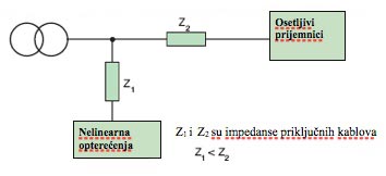
Slika 5. Izmeštanje nelinearnih prijemnika - Grupisanje nelinearnih prijemnika,koji se priključuju na odvojene sabirnice.
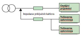
Slika 5.1. Priključenje više nelinearnih prijemnika
. - Instaliranje više transformatora,jedni napajaju nelinearne prijemnike,dok drugi napajaju linearne prijemnike.
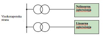
Slika 5.2. Posebni transformatori za posebne vrste prijemnika
. - Odgovarajućim sprezanjem transformatora mogu se ograničiti viši harmonici. Sprega namotaja u trougao dovodi do blokiranja daljeg toka svih harmonika, koji su umnozak od 3. Unošenjem faznog pomeraja od 30 stepeni, sprezanjem sekundara transformatora u zvezdu i u trougao, dobija se efekat 12-pulsnog ispravljača, odnosno eliminišu se 5-ti i 7-mi harmonik.
Slika 5.3. Različito sprezanje namotaja utiče na eliminisanje pojedinih harmonika
.
Uskoro u nastavku stručnog teksta: EES Kvalitet električne energije – viši harmonici (2):
- Postavljanje filtera (pasivni, aktivni i hibridni)
- Popravka faktora snage
- Standardi i preporuke (u Francuskoj, Švedskoj, Australiji)
- Standardi i preporuke međunarodne elektrotehničke komisije (IEC)
.
AUTOR STRUČNOG TEKSTA:
Dragan Simović
![]()
Seminarski rad iz predmeta: Eksploatacija EES, tema: Kvalitet električne energije – viši harmonici
Visoka Škola Tehničkih Strukovnih Studija Čačak
Specijalističke Strukovne Studije Elektrotehnike i Računarstva | Modul Studijskog Programa: Elektroenergetika
.
Related articles
- EES Kvalitet električne energije – viši harmonici (2)
- Busbar Technical Specification
- Koji proizvodjac opreme Vam najvise “lezi”?
10,008 views
International Standard - IEC 61850
The traditional approach to substation integration used standardized RTU protocols that were designed to provide protocol efficiency for operation over bandwidth limited serial links.
While such limitations remain for many applications, substation hardened equipment implementing modern networking standards like Ethernet now provide a cost effective means of enabling high speed communications within the substation.
To truly take advantage of this technology and dramatically lower the total cost of ownership of substation automation systems, a new approach to substation integration that goes beyond a simple RTU protocol is needed.
The recent international standard IEC 61850 proposes a unified solution of the communication aspect of substation automation. However, the standard itself is not easily understood by users other than domain experts. We present our understanding of the IEC 61850 standard as well as the design and implementation of our simulation tool in this report. Also, we give suggestions on the implementation of this standard based on our experience and lessons in the development of our simulation.
1. Introduction
Today, power substations are mostly managed by substation automation systems. These systems employ computers and domain specific applications to optimize the management of substation equipment and to enhance operation and maintenance efficiencies with minimal human intervention [8].
Once upon a time, substation automation systems utilized simple, straightforward and highly specialized communication protocols [7]. These protocols concerned less about the semantics of the exchanged data, data types of which were relatively primitive. Equipment was dumb and systems were simple. However, today’s substation automation systems can no longer enjoy such simplicity because of their growing complexity — equipment becomes more intelligent and most of those simple old systems have been gradually replaced by open systems, which embrace the advantage of emerging technology like relational database systems, multi-task operating systems and support for state-of-the-art graphical display technology.
Besides, devices from different manufacturers used different substation automation protocols [9, 3, 12], disabling them to talk to each other. Utilities have been paying enormous money and time to configure these devices to work together in a single substation. Today most utilities and device manufacturers have recognized the need for a unified international standard to support seamless cooperation among products from different vendors.
The IEC 61850 international standard, drafted by substation automation domain experts from 22 countries, seeks to tackle the aforementioned situation. This standard takes advantage of a comprehensive object-oriented data model and the Ethernet technology, bringing in great reduction of the configuration and maintenance cost. Unlike its predecessor, the Utility Communication Architecture protocol 2.0 (UCA 2.0) [12], the IEC 61850 standard is designed to be capable for domains besides substation automation. To make the new protocol less domain dependent, the standard committee endeavored to emphasize on the data semantics, carving out most of the communication details. This effort, however, could result in difficulties in understanding the standard.
In this research project, we aim to get a clear understanding of the IEC 61850 standard and simulate the protocol based on J-Sim [11]. Our ultimate goal is to investigate the security aspect about the IEC 61850 standard.
2 The IEC 61850 standard
The first release of the IEC 61850 consists of a set of documents of over 1,400 pages. These documents are divided into 10 parts, as listed in Table 1. Part 1 to Part 3 give some general ideas about the standard. Part 4 defines the project and management requirements in an IEC 61850 enabled substation. Part 5 specifies the required parameters for physical implementation. Part 6 defines an XML based language for IED configuration, presenting a formal view of the concepts in the standard. Part 7 elaborates on the logical concepts, which is further divided into four subparts (listed in Table 2). Part 8 talks about how to map the internal objects to the presentation layer and to the Ethernet link layer. Part 9 defines the mapping from sampled measurement value (SMV) to point-to-point Ethernet.
The last part gives instructions on conformance testing. Since Part 7 defines the core concepts of the IEC 61850 standard, we will focus on this part in this report.
| Subpart | Title |
| 7.1 | .Principles and Models |
| 7.2 | .Abstract Communication Service Interface |
| 7.3 | .Common Data Classes |
| 7.4 | .Compatible Logical Node Classes and Data Classes |
| Table 2: Subparts of IEC 61850-7 | |
The IEC 61850 standard is not easy to understand for people other than experts in the substation automation domain due to the complexity of the documents and the assumed domain-specific knowledge. Introductory documents on the standard abound [13, 4, 7, 5, 8, 2], but most of them are in the view of substation automation domain experts. Kostic et al. explained the difficulties they had in understanding the IEC 61850 standard [7].
In this section, we provide another experience of understanding this standard, trying to explain the major concepts of the IEC 61850 standard.
2.1 Challenges
Understanding the IEC 61850 standard proposes the following challenges for a outsider of the substation automation domain:
- As a substation automation standard proposed by a group of domain experts, the IEC 61850 protocol assumes quite an amount of domain-specific knowledge, which is hardly accessible by engineers and researchers out of the substation automation domain. To make things worse, the terms used in the standard is to some extent different from those commonly used in software engineering, bringing some difficulties for software engineers in reading the standard.
- The entire standard, except Part 6, is described in natural language with tables and pictures, which is known to be ambiguous and lack of preciseness. This situation is problematic because the IEC 61850 concepts are defined by more than 150 mutually relevant tables distributed over more than 1,000 pages. A formal presentation of all these concepts would be appreciated.
- The experts proposing this protocol come from 22 different countries and are divided into 10 working groups, each responsible to one part of the standard. Due to the different backgrounds and the informal presentation style of the standard, the standard contains a considerable number of inconsistencies. Such inconsistencies are more obvious for different parts of the standard, e.g. the data model described in Part 6 is clearly different from that described in Part 7.
- The standard committee made a great effort to describe the protocol in an object-oriented manner but the result is not so object-oriented. For example, the ACSI services are grouped by different classes, but reference to the callee object is not defined as a mandatory argument of the service function.
- The standard is designed to be implementation independent but this is not always true. For example, the data attribute TimeAccuracy in Part 7-2 Table 8 is defined as CODED ENUM, while what it virtually represents is a 5-bit unsigned integer; the frequent use of PACKED LIST (i.e. “bit fields” in the C language) also brings implementation details to interface design.
- Things are mixed up in the documents. Mandatory components and optional components are mixed in the standard, and domain independent concepts are mixed up with domain specific concepts. Even though the optional components and mandatory ones are marked with “O” and “M” alternatively, it would be a tough task to refine a model consisting only the mandatory components due to the implicit dependences between attributes in different tables and the conditional inclusion of some attributes. In fact, there are 29 common data classes and 89 compatible logical nodes defined in the standard, the relationship among which is unclear.
.
2.2 Intelligent electronic device
In the past, utility communication standards usually assumed some domain-specific background of the readers. Consequently, they contained a lot of implicit domain knowledge, which is hardly accessible to outsiders (e.g. software engineers) [7]. The IEC 61850 standard does not escape from this category. To help understanding the logical concepts of IEC 61850, we would like to lay a basic idea of intelligent electronic devices (IED), the essential physical object hosting all the logical objects.
Basically, the term intelligent electronic device refers to microprocessor-based controllers of power system equipment, which is capable to receive or send data/control from or to an external source [8]. An IED is usually equipped with one or more microprocessors, memory, possibly a hard disk and a collection of communication interfaces (e.g. USB ports, serial ports, Ethernet interfaces), which implies that it is essentially a computer as those for everyday use.
However, IEDs may contain some specific digital logics for domain-specific processing.
IEDs can be classified by their functions. Common types of IEDs include relay devices, circuit breaker controllers, recloser controllers, voltage regulators etc.. It should be noted that one IED can perform more than one functions, taking advantage of its general-purpose microprocessors. An IED may have an operating system like Linux running in it.
| Part | Title |
| 1 | .Introduction and Overview |
| 2 | .Glossary |
| 3 | .General Requirements |
| 4 | .System and Project Management |
| 5 | .Communication Requirements for Functions and Device .Models |
| 6 | .Configuration Description Language for Communication in .Electronic Substations Related to IEDs |
| 7 | .Basic Communication Structure for Substation and Feeder .Equipment |
| 8 | .Specific Communication Service Mapping (to MMS and to .Ethernet) |
| 9 | .Specific Communication Service Mapping (from Sampled .Values) |
| 10 | .Conformance Testing |
| Table 1: Parts of the IEC 61850 standard documents | |
2.3 Substation architecture
A typical substation architecture is shown in Figure 1. The substation network is connected to the outside wide area network via a secure gateway. Outside remote operators and control centers can use the abstract communication service interface (ACSI) defined in Part 7-2 to query and control devices in the substation. There is one or more substation buses connecting all the IEDs inside a substation. A substation bus is realized as a medium bandwidth Ethernet network, which carries all ACSI requests/responses and generic substation events messages (GSE, including GOOSE and GSSE).
There is another kind of bus called process bus for communication inside each bay. A process bus connects the IEDs to the traditional dumb devices (merge units, etc.) and is realized as a high bandwidth Ethernet network. A substation usually has only one global substation bus but multiple process buses, one for each bay.

Figure 1: Substation architecture
ACSI requests/responses, GSE messges and sampled analog values are the three major kinds of data active in the substation network. Since we are less interested in communication on the process buses (like sampled value multicasting), we focus on the activities on the substation bus in this report, especially the ACSI activities.
Interactions inside a substation automation system mainly fall into three categories: data gathering/setting, data monitoring/reporting and event logging.
The former two kinds of interactions are the most important — in the IEC 61850 standard all inquiries and control activities towards physical devices are modeled as getting or setting the values of the corresponding data attributes, while data monitoring/reporting provides an efficient way to track the system status, so that control commands can be issued in a timely manner.
To realize the above kinds of interaction, the IEC 61850 standard defines a relatively complicated communication structure, as is shown in Figure 2.

Figure 2: The communication profiles
Five kinds of communication profiles are defined in the standard: the abstract communication service interface profile (ACSI), the generic object oriented substation event profile (GOOSE), the generic substation status event profile (GSSE), the sampled measured value multicast profile (SMV), and the time synchronization profile. ACSI services enable client-server style interaction between applications and servers.
GOOSE provides a fast way of data exchange on the substation bus and GSSE provides an express way of substation level status exchange. Sample measured value multicast provides an effective way to exchange data on a process bus.
.
2.4 Abstract communication service interface
ACSI is the primary interface in the IEC 61850 standard not only because it is the interface via which applications talk with servers, but also in the sense that the ACSI communication channel is an important part of a logical connection between two logical nodes. ACSI defines the semantics of the data exchanged between applications and servers, thus it becomes the major part of the IEC 61850 standard.
The standard committee adopt an object-oriented approach in the design of ACSI, which includes a hierarchical and comprehensive data model and a set of available services for each class in this data model. Although the data model is usually described outside the scope of the ACSI, it is actually part of it. The benefits of using an object-oriented utility communication interface are two fold. On the one hand, objects (e.g. registers) can be referenced in an intuitive way (e.g. “Relay0/MMXU0.voltage”) instead of by the traditional physical address (like Reg#02432). On the other hand, software engineers can build more reliable applications using such service interface.
In the following two sections, we present a brief description on these two ACSI components.
.
2.5 Data model
The hierarchical data model defined in the IEC 61850 is depicted in Figure 3 and Figure 4.
Server is the topmost component in this hierarchy. It serves as the joint point of physical devices and logical objects. Theoretically one IED may host one or more server instances, but in practice usually only one server instance runs in an IED. A server instance is basically a program running in an IED, which shares the same meaning with other servers like FTP server etc.. Each server has one or more access points, which are the logical representation of a NIC. When a client is to access data or service of the server, it should connect to an access point of this server and establish a valid association.
Each server hosts several files or logical devices. Clients can manipulate files in the server like talking to a FTP server, which is usually used as a means to upload/update the configuration file of an IED. A logical device is the logical correspondence of a physical device. It is basically a group of logical nodes performing similar functions.
Functions supported by an IED are conceptually represented by a collection of primitive, atomic functional building blocks called logical nodes.
The IEC 61850 standard predefines a collection of template logical nodes (i.e. compatible logical nodes) in Part 7-4. Besides the regular logical nodes for functions, the standard also requires every logical device have two specific logical nodes: Logical Node Zero (LN0) and LPHD, which correspond to the logical device and the physical device, alternatively. Besides holding status information of the logical device, LN0 also provides additional functions like setting-group control, GSE control, sampled value control etc..
In the IEC 61850 standard, the entire substation system is modeled as a distributed system consisting of a collection of interacting logical nodes, which are logically connected by logical connections. It should be noted that the term logical connection refers to the logical concept of the connections between two logical nodes, which can be direct or indirect or even a combination of many different kinds of communication channels. In fact, the connection of two logical nodes is usually both indirect and a combination of TCP, UDP and direct Ethernet connections. We will explain logical connections in Section 2.9 (next article).
Data exchanged between logical nodes are modeled as data objects. A logical node usually contains several data objects. Each data object is an instance of the DATA class and has a common data class type.

Figure 3: Hierarchy of the IEC 61850 data model
Similar to the concept of objects in most object-oriented programming languages, a data object consists of many data attributes, which are instances of data attributes of the corresponding common data class. Data attributes are typed and restricted by some functional constraints. Instead of grouping data attributes by data objects, functional constraints provide a way to organize all the data attributes in a logical node by functions. Types of data attributes can be either basic or composite.
Basic types are primitive types in many programming languages, whereas composite types are composition of a collection of primitive types or composite types.
In the IEC 61850 standard, data attributes are at least as important as, if not more than, data objects for two reasons.

Figure 4: The data model of the IEC 61850
Firstly, data objects are just logical collections of the contained data attributes while (primitive) data attributes are the de facto logical correspondence to the physical entities (memory units, registers, communication ports, etc.); secondly, the purpose of data objects is for the convenience of managing and exchanging values of a group of data attributes sharing the same function.
Despite data objects, the IEC 61850 standard provides the concept of data set as another ways to manage and exchange a group of data attributes. Members of a data set can be data objects or data attributes. The concept of data set is somewhat similar to the concept of view in the area of database management systems.
In the IEC 61850 standard, most services involve data sets. Members in a data set unnecessarily come from the same logical node or the same data object, thus providing high flexibility of data management. Data sets are categorized into permanent ones and temporary ones.
Permanent data sets are hosted by logical nodes and will not be automatically deleted unless on the owners’ explicit requests; temporary data sets are exclusively hosted by the association having created them and will be automatically deleted when the association ends.
To be continued soon in next article: IEC 61850 in details (2)
SOURCE:
- Understanding and Simulating the IEC 61850 Standard by Yingyi Liang & Roy H. Campbell, Department of Computer Science University of Illinois at Urbana-Champaign
.
Related articles
- IEC 61850 Standard In Details (2)
- Benefits Of IEC 61850
- Testing performances of IEC 61850 GOOSE messages
- Testiranje performansi IEC 61850 GOOSE poruka
- The New ETS4: Easy, Fast, Open
6,457 views

Maintenance Of Low Voltage Circuit Breakers
The deterioration of low voltage circuit breaker is normal and this process begins as soon as the circuit breaker is installed. If deterioration is not checked, it can cause failures and malfunctions. The purpose of an electrical preventive maintenance and testing program should be to recognize these factors and provide means for correcting them.
A good organized maintenance program can minimize accidents, reduce unplanned shutdowns and lenghten the mean time between failures of electrical equipment.
Benefits of good electrical equipment maintenance can be reduced cost of process shutdown (caused by circuit breaker failure), reduced cost of repairs, reduced downtime of equipment, improved safety of personnel and property.
Frequency Of Maintenance
Low-voltage circuit breakers operating at 600 volts alternating current and below should be inspected and maintained very 1 to 3 years, depending on their service and operating conditions. Conditions that make frequency maintenance and inspection necessary are:
- High humidity and high ambient temperature.
- Dusty or dirty atmosphere.
- Corrosive atmosphere.
- Frequent switching operations.
- Frequent fault operations.
- Older equipment.
A breaker should be inspected and maintained if necessary whenever it has interrupted current at or near its rated capacity.
Maintenance Procedures
Manufacturer’s instructions for each cir cuit breaker should be carefully read and followed. The following are general pro cedures that should be followed in the maintenance of low-voltage air circuit breakers:
- An initial check of the breaker should be made in the TEST position prior to withdrawing it from to enclosure.
- Insulating parts, including bushings, should be wiped clean of dust and smoke.
- The alignment and condition of the movable and stationary contacts should be checked and adjusted according to the manufacturer’s instruction book.
- Check arc chutes and replaces any damaged parts.
- Inspect breaker operating mechanism for loose hardware and missing or broken cotter pins, etc. Examine cam, latch, and roller surfaces for damage or wear.
- Clean and relubricate operating mechanism with a light machine oil (SAE-20 or 30) for pins and bearings and with a nonhardening grease for the wearing surfaces of cams, rollers, etc.
- Set breaker operating mechanism adjustments as described in the manufacturer’s instruction book. If these adjustments cannot be made within the specified tolerances, it may indicate excessive wear and the need for a complete overhaul.
- Replace contacts if badly worn or burned and check control device for freedom of operation.
- Inspect wiring connections for tightness.
- Check after servicing circuit breaker to verify the contacts move to the fully opened and fully closed positions, that there is an absence of friction or binding, and that electrical operation is functional.
Much of the essence of effective electrical equipment preventive maintenance can be sumarrized by four rules:
- Keep it DRY
- Keep it CLEAN
- Keep it COOL
- Keep it TIGHT
SOURCES:
- MAINTENANCE OF POWER CIRCUIT BREAKERS by HYDROELECTRIC RESEARCH AND TECHNICAL SERVICES GROUP
- ELECTRICAL POWER EQUIPMENT MAINTENANCE AND TESTING – By Paul Gill
.
Related articles
- Maintenance Of Meduim Voltage Circuit Breakers
- GE AKD-20 Low-Voltage Switchgear
- Maintenance Of SF6 Gas Circuit Breakers
- Siemens MV Topic – Loss Of Vacuum
- Maintenance Of High Voltage Circuit Breakers
")
Maintenance Of Molded Case Circuit Breakers (MCCB)
The maintenance of circuit breakers deserves special consideration because of their importance for routine switching and for protection of other equipment.
Electric transmission system breakups and equipment destruction can occur if a circuit breaker fails to operate because of a lack of preventive maintenance.
The need for maintenance of circuit breakers is often not obvious as circuit breakers may remain idle, either open or closed, for long periods of time. Breakers that remain idle for 6 months or more should be made to open and close several times in succession to verify proper operation and remove any accumulation of dust or foreign material on moving parts and contacts.
Frequency Of Maintenance
Molded case circuit breakers are designed to require little or no routine maintenance throughout their normal life time. Therefore, the need for preventive maintenance will vary depending on operating conditions. As an accumulation of dust on the latch surfaces may affect the operation of the breaker, molded case circuit breakers should be exercised at least once per year.
Routine trip testing should be performed every 3 to 5 years.
Routine Maintenance Tests
Routine maintenance tests enable personnel to determine if breakers are able to perform their basic circuit protective functions. The following tests may be performed during routine maintenance and are aimed at assuring that the breakers are functionally operable. The following tests are to be made only on breakers and equipment that are deenergized.
Insulation Resistance Test
A megohmmeter may be used to make tests between phases of opposite polarity and from current-carrying parts of the circuit breaker to ground. A test should also be made between the line and load terminals with the breaker in the open position. Load and line conductors should be dis connected from the breaker under insulation resistance tests to prevent test mesurements from also showing resistance of the attached circuit.
Resistance values below 1 megohm are considered unsafe and the breaker should be inspected for pos sible contamination on its surfaces.
Milivolt Drop Test
A millivolt drop test can disclose several abnor mal conditions inside a breaker such as eroded contacts, contaminated contacts, or loose internal connec tions. The millivolt drop test should be made at a nominal direct-current volt age at 50 amperes or 100 amperes for large breakers, and at or below rating for smaller breakers. The millivolt drop is compared against manufacturer’s data for the breaker being tested.
Connections Test
The connections to the circuit breaker should be inspected to determine that a good joint is present and that overheating is not occurring. If overheating is indi cated by discoloration or signs of arcing, the connections should be re moved and the connecting surfaces cleaned.
Overload tripping test
The proper action of the overload tripping components of the circuit breaker can be verified by applying 300 percent of the breaker rated continuous current to each pole. The significant part of this test is the automatic opening of the circuit breaker and not tripping times as these can be greatly affected by ambient conditions and test condi tions.
Mechanical operation
The mechanical operation of the breaker should be checked by turning the breaker on and off several times.
SOURCE: HYDROELECTRIC RESEARCH AND TECHNICAL SERVICES GROUP
.
Related articles
- Line Protection With Distance Relays
- UPS design criteria and selection
- Current Switching with High Voltage Air Disconnector
- Standard IEC 60947-2
- Maintenance Of SF6 Gas Circuit Breakers
16,593 views

Caterpillar C175 Diesel Generator 2-4MW
The C175 family of diesel generator sets offers the most power you can get in any single high-speed package: 2-4MW.
One of the most significant components in the development of the C175 was the integration of ACERT™ Technology into the engine platform.
ACERT Technology is a synergistic approach utilizing a suite of complementary building block technologies that can be individually adapted to accommodate a specific application. In recent years, Caterpillar has spent more than $1 billion on the development of clean diesel technologies. Today, more than 330,000 engines are currently in operation with ACERT Technology, accumulating more than 2 million hours of use each day.
With the C175, the building blocks of ACERT Technology have been tailored to meet the current and pending emissions requirements of stationary diesel generator sets in a variety of applications.
Advantages
Thousands of hours of customer research created the foundation for the C175 design concept.
Some of the major advantages of the C175 family include:
- Proven Reliability with platform based on industry standard Cat® 3500 series, and supported by thousands of hours of lab and field-testing.
- Wider Power Range including 2000kW to 4000kW @ 1500 and 1800 rpm.
- Power Generation at Higher Speed than traditional medium speed products in the same power range.
- Higher Power Density equals more output from a given engine displacement / footprint, resulting in lower installed cost.
- Complete Package including SR5 generators, EMCP3 package controls and package/remote radiator with flexible controls packaging options simplifies installation.
- Lower Emissions meet U.S. EPA Tier 2 standards with a line of sight to meet U.S. EPA Tier 4 and EU Stage IIIB emissions levels.
- Lower Maintenance Costs due to increased oil change intervals, longer life (durability) of components and longer top end as well as full overhaul periods.
- Lower Operating Costs due to lower brake specific fuel consumption than competitive products.
- Systems Integration. The C175 electrical system components are engineered to work together with a wide range of products such as Uninterruptible Power Supplies (UPS), Automatic Transfer Switches (ATS), switchgear, remote monitoring services and customer building SCADA systems.
- Extensive Product Support from a worldwide dealer network with 24/7/365 parts and service availability.
Design Features
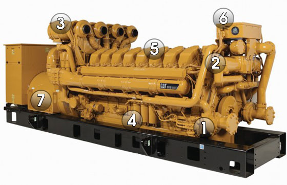
1. Fuel System

C175 - Fuel System
The new C175 engine features a Cat® Common Rail Fuel System designed specifically for this engine platform.
Full Control of Both Fuel Delivery and Fuel Pressure At Any Load or Speed results in superior transient response and block load acceptance, as well as shorter recovery time.
More Compact single camshaft that is used only to open the intake and exhaust valves. It features a simpler injection design with no pumping function necessary.
Improved Cold Start Capability uses higher pressures at low speeds and produces less smoke.
“Fluid Containment” Design. The high-pressure lines and rails are designed to provide outer concentric low-pressure containment. If a leak occurs in the high-pressure section, it leaks back to the outer low-pressure section and drains back to the tank.
Integrated Manifold or Monoblock offers a single point of connection to the engine, which eliminates leak paths while improving reliability.
Fuel Cooler Eliminated. Unlike the unit injector system, the Common Rail System used on the C175 does not require excess bypass fuel to cool the injector since injection pressure load is taken off the injector. The result is a reduction of heat generation in the return fuel and reduction in fuel flow rate by a factor of 4 when compared to the unit injector system. This eliminates the need for a fuel cooler in most cases.
Improved Fuel Filters. The C175 uses an eco-friendly fuel filter system. Instead of throwing away the whole canister, only the disposable non-metallic element inside the canister is changed.
Electronic Fuel Priming Pump is Engine Control Module (ECM)-controlled and offered as standard equipment. No manual effort is required to pump the fuel, so it’s more convenient and requires less operator effort.
2. Cooling System

C175 - Cooling System
The design philosophy for the Cat® C175 cooling system is to minimize heat rejection by cooling only the parts that require cooling.
Inlet-Regulated System. The C175 features an innovative design unique to Caterpillar. The system senses the temperature at the inlet and controls the output providing more consistent temperatures and better control of oil viscosity than an outlet-regulated system.
Electronic Fluid Temperature Controller regulates inlet temperature of the coolant and allows for troubleshooting without removing the thermostat. Improved diagnostics enable the operator to pinpoint a problem quickly, which increases reliability and uptime.
Integral Water Supply and Return Manifold are built into the engine block to minimize connection points and bolted joints. This design helps contain fluids and improves overall engine reliability and serviceability.
Two-Stage After-Cooler. The first stage is cooled by a jacket water circuit and the second stage has a two-pass separate circuit. The after-cooler is constructed with tube fin cores that are more robust compared to the traditional bar plate fin design. The tubes of the core can be cleaned without removing the core from the engine, and the core can be remanufactured. The tubes also have more surface area per volume and less pressure drop, resulting in more efficient cooling. This after-cooler design also minimizes the size of the SCAC circuit, thereby reducing the size of the radiator. The location of the first stage jacket water core provides protection from high air temperatures. These features improve the durability and reliability of the cooling system.
3. Air Management

C175 - Air Management
Air management is one of the ACERT™ Technology building blocks used on the Cat® C175 engine.
Crossflow Head provides separation between both the intake and exhaust ports and manifolds. The outboard air manifold location eliminates re-heating of intake air by preventing heat transfer from the exhaust to the intake. This results in reduced charge air temperature and increased charge air density, enabling higher power density as well as reducing SCAC cooling.
Taller Head accommodates larger ports and helps direct a large amount of cool air into the cylinder with the least resistance, resulting in the best port performance of any engine in the world. The taller head also accommodates increased valve lift of 22mm compared to 18mm on the Cat 3500, further improving breathing.
Improved Breathing. The tall crossflow head results in a greater amount of cooler air in and out of the engine, which helps produce higher power ratings and lower emissions. This, along with lower air pumping losses, results in lower fuel consumption.
New Generation of Turbochargers designed specifically for the C175. Four single-stage turbochargers provide a higher pressure ratio in a single stage. The turbocharger includes a cast titanium impeller and an improved bearing system that provides a higher load-bearing capacity and greater reliability, while increasing efficiency by 5% and extending the component life when compared to traditional cast aluminum impellers.
4. Lube System

C175 - Lube Management
The C175 lube system features two piston-cooling jets per piston.
A large capacity oil pump pressure regulation valve allows the engine to maintain optimum oil pressure at all speeds, loads and throughout the life of the engine, ultimately increasing durability.
.
.
.
5. Core Engine Components

C175 - Core Engine Components
The components of the new C175 centerline engine are designed for higher strength, durability and compactness.
Crankshaft has a larger diameter to handle bigger loads. It is made of steel forged material and features induction hardened fillets and journals. Thrust plates are located at the rear end of the crankshaft to reduce motion inside of the coupling between the engine and generator.
Block is made of cast iron and provides increased strength and stiffness, and is lighter weight.
Mid-Support Liners provide stronger support to the liner and offer more efficient cooling by only cooling the top 25% of the cylinder liner. Mid-support liners allow for a smaller inside diameter of the combustion seal, as well as a higher position for the piston’s top ring. The result is reduced crevice volume, improved cooling and combustion efficiency, and reduced emissions. Mid-support liners allow the head bolts to be closer to the cylinder bore to minimize cylinder spacing and to create a more compact engine.
Cylinder Cuff is specially designed for improved durability. The ring of the “cuff” located at the top of the cylinder scrapes off carbon accumulation on the piston top end, preventing the carbon from polishing, scratching or seizing the liner. The cuff also helps reduce crevice volume beside the piston, resulting in lower emissions.
Cylinder Head is made of iron for added strength. The tall C175 head helps eliminate the external water manifold by returning the coolant to the cylinder block.
Head Gasket features a simplified two-piece (carrier seal and combustion seal) design, shortening service time, decreasing parts costs, and increasing reliability and durability.
Pistons and Rings feature increased oil flow to pistons for better cooling and higher power ratings. Rectangular piston rings provide a superior seal and less motion, resulting in less wear and longer life. Piston, rod and liner come out as one assembly, resulting in faster, easier service.
Connecting Rods. Large diameter fracture split connecting rods provide better alignment between the rod and cap, which eliminates the need for a special alignment procedure.
Bearings. Large main and rod bearings provide better seizure resistance and better tolerance of a wide range of oil temperatures. Larger rod bearing and main bearing are more scuff and seizure resistant.
6. Engine Management System

C175 - Engine Management System
The Cat® C175 utilizes much of the ACERT™ Technology electronics experience gained on small-bore engines and employs many new improvements and technologies more useful on large bore engines. The C175 Engine Management System exploits the power of modern control technology to improve reliability, exceed customer expectations and accommodate future customer requirements.
Engine Control Module (ECM). C175 engine controls use the latest version of the ADEM™ A4 ECM to deliver 50 times the computing power of its predecessor. Specific benefits include monitoring over 30 points on the engine, driving up to 20 injectors, protecting the engine, communicating over 100 engine parameters to the customer, diagnosing and reporting on engine health. The ECM uses the latest advancements in ACERT Technology to improve engine performance while reducing emissions.
Engine Controls and Datalink. Three primary controllers are temperature control module, fuel high-pressure controller and ECM. These are connected to the engine J1939 datalink.
Rigid Wiring Harness. Metal enclosed rigid wiring harness system protects critical engine circuits from accidental damage, reducing service calls and increasing reliability.
Controls Packaging. The standard panel is a rear-mounted EMCP 3.1 with the option to upgrade to the EMCP 3.2 or EMCP 3.3.
7. Generator

C175 - Generator
Caterpillar is introducing the next evolution of generators, the SR5 Series, with the introduction of the C175 generator sets. The SR5 Series 1800 and 3000 frame generators have been designed specifically to work with the C175 engines. The structural design is matched to the C175 engine. Torsional and linear vibration analysis and testing have been performed to ensure durability.
The SR5 generator’s insulation system has been improved to meet insulation Class H. SR5 generators feature 2/3-pitch as standard on all low, medium and high voltage generators. SR5 generators have IP23 particle ingress protection.
Generator Set Packaging. The C175 uses a fusible coupling to connect the generator to the engine. All engines, generators and controls are tested individually prior to assembly. Once assembled, the entire generator set package is tested before shipping to dealers to ensure quality.
Applications
The versatility of the C175 makes it ideal for a variety of applications.
- Continuous – A continuous rating has a typical load factor of 70% to 100% with no limit on the number of hours per year. Typical peak demand is 100% of continuous rated kW for 100% of operating hours. Typical applications include base load, utility or co-generation.
- Prime – A prime rating has a typical load factor of 60% to 70% with no limit on the number of hours per year. Typical peak demand is 100% of prime rated kW with 10% overload available for emergency use for up to one hour in 12. Typical applications include industrial, pumping, construction, peak shaving or co-generation.
- Standby – A standby rating has a typical load factor of 70% or less with variable load for about 200 hours per year,with a maximum expected usage of 500 hours per year. Typical peak demand is 80% of the standby rated kW with power available for the duration of an emergency outage. Typical applications include building service standby or emergency standby.
- Load Management – A load management rating has a typical load factor of 100% of the prime rating for a maximum of 500 hours per year. Typical peak demand is 100% of the load management rating, with no overload available. Typical applications include base load or peak shaving.
SOURCE: Caterpillar C175
.
Related articles
- Transformer Ratings
- Bus Joint Fundamentals
- Hydropower – Systems Overview (2)
- Transformer heating and cooling
- Comparison Between Vacuum and SF6 Circuit Breaker
7,138 views

Lighting Fundamentals
Illuminance is light falling on a surface measured in footcandles or lux. Distributed with an economic and visual plan, it becomes engineered lighting and, therefore, practical illumination.
A lighting designer has four major objectives:
1. Provide the visibility required based on the task to be performed and the economic objectives.
2. Furnish high quality lighting by providing a uniform illuminance level, where required, and by minimizing the negative effects of direct and reflected glare.
3. Choose luminaires aesthetically complimentary to the installation with mechanical, electrical and maintenance characteristics designed to minimize operational expense.
4. Minimize energy usage while achieving the visibility, quality and aesthetic objectives.
CONTENTS
.
1. ILLUMINATION
| 1.1 | Quantity of Illumination | |
| 1.2 | Quality of Illumination |
.
.
1.1 Quantity of Illumination
Light Output

Light Output - Light Level - Brightness
The most common measure of light output (or luminous flux) is the lumen. Light sources are labeled with an output rating in lumens.
For example, a T12 40-watt fluorescent lamp may have a rating of 3050 lumens. Similarly, a light fixture’s output can be expressed in lumens. As lamps and fixtures age and become dirty, their lumen output decreases (i.e., lumen depreciation occurs).
Most lamp ratings are based on initial lumens (i.e., when the lamp is new).
.
Light Level
Light intensity measured on a plane at a specific location is called illuminance. Illuminance is measured in footcandles, which are workplane lumens per square foot. You can measure illuminance using a light meter located on the work surface where tasks are performed. Using simple arithmetic and manufacturers’ photometric data, you can predict illuminance for a defined space. (Lux is the metric unit for illuminance, measured in lumens per square meter. To convert footcandles to lux, multiply footcandles by 10.76.)
Brightness
Another measurement of light is luminance, sometimes called brightness. This measures light “leaving” a surface in a particular direction, and considers the illuminance on the surface and the reflectance of the surface.
The human eye does not see illuminance; it sees luminance. Therefore, the amount of light delivered into the space and the reflectance of the surfaces in the space affects your ability to see.
Quantity Measures
- Luminous flux is commonly called light output and is measured in lumens (lm).
- Illuminance is called light level and is measured in footcandles (fc).
- Luminance is referred to as brightness and is measured in footlamberts (fL) or candelas/m2 (cd/m2).
Determining Target Light Levels
The Illuminating Engineering Society of North America has developed a procedure for determining the appropriate average light level for a particular space. This procedure ( used extensively by designers and engineers ( recommends a target light level by considering the following:
- the task(s) being performed (contrast, size, etc.)
- the ages of the occupants
- the importance of speed and accuracy
Then, the appropriate type and quantity of lamps and light fixtures may be selected based on the following:
- fixture efficiency
- lamp lumen output
- the reflectance of surrounding surfaces
- the effects of light losses from lamp lumen depreciation and dirt accumulation
- room size and shape
- availability of natural light (daylight)
When designing a new or upgraded lighting system, one must be careful to avoid overlighting a space. In the past, spaces were designed for as much as 200 footcandles in places where 50 footcandles may not only be adequate, but superior. This was partly due to the misconception that the more light in a space, the higher the quality. Not only does overlighting waste energy, but it can also reduce lighting quality. Refer to Exhibit 2 for light levels recommended by the Illuminating Engineering Society of North America. Within a listed range of illuminance, three factors dictate the proper level: age of the occupant(s), speed and accuracy requirements, and background contrast.
For example, to light a space that uses computers, the overhead light fixtures should provide up to 30 fc of ambient lighting. The task lights should provide the additional footcandles needed to achieve a total illuminance of up to 50 fc for reading and writing. For illuminance recommendations for specific visual tasks, refer to the IES Lighting Handbook, 1993, or to the IES Recommended Practice No. 24 (for VDT lighting).
Quality Measures
- Visual comfort probability (VCP) indicates the percent of people who are comfortable with the glare from a fixture.
- Spacing criteria (SC) refers to the maximum recommended distance between fixtures to ensure uniformity.
- Color rendering index (CRI) indicates the color appearance of an object under a source as compared to a reference source.
1. ILLUMINATION ↑ | CONTENTS ↑ | TOP ↑
1.2 Quality of Illumination
Improvements in lighting quality can yield high dividends for US businesses. Gains in worker productivity may result by providing corrected light levels with reduced glare. Although the cost of energy for lighting is substantial, it is small compared with the cost of labor. Therefore, these gains in productivity may be even more valuable than the energy savings associated with new lighting technologies. In retail spaces, attractive and comfortable lighting designs can attract clientele and enhance sales.
Three quality issues are addressed in this section.
- Glare
- Uniformity of Illuminance on Tasks
- Color Rendition
Glare
Perhaps the most important factor with respect to lighting quality is glare. Glare is a sensation caused by luminances in the visual field that are too bright. Discomfort, annoyance, or reduced productivity can result.
A bright object alone does not necessarily cause glare, but a bright object in front of a dark background, however, usually will cause glare. Contrast is the relationship between the luminance of an object and its background. Although the visual task generally becomes easier with increased contrast, too much contrast causes glare and makes the visual task much more difficult.
You can reduce glare or luminance ratios by not exceeding suggested light levels and by using lighting equipment designed to reduce glare. A louver or lens is commonly used to block direct viewing of a light source. Indirect lighting, or uplighting, can create a low glare environment by uniformly lighting the ceiling. Also, proper fixture placement can reduce reflected glare on work surfaces or computer screens. Standard data now provided with luminaire specifications include tables of its visual comfort probability (VCP) ratings for various room geometries. The VCP index provides an indication of the percentage of people in a given space that would find the glare from a fixture to be acceptable. A minimum VCP of 70 is recommended for commercial interiors, while luminaires with VCPs exceeding 80 are recommended in computer areas.
Uniformity of Illuminance on Tasks
The uniformity of illuminance is a quality issue that addresses how evenly light spreads over a task area. Although a room’s average illuminance may be appropriate, two factors may compromise uniformity.
- improper fixture placement based on the luminaire’s spacing criteria (ratio of maxim recommended fixture spacing distance to mounting height above task height)
- fixtures that are retrofit with reflectors that narrow the light distribution
Non-uniform illuminance causes several problems:
- inadequate light levels in some areas
- visual discomfort when tasks require frequent shifting of view from underlit to overlit areas
- bright spots and patches of light on floors and walls that cause distraction and generate a low quality appearance
Color Rendition
The ability to see colors properly is another aspect of lighting quality. Light sources vary in their ability to accurately reflect the true colors of people and objects. The color rendering index (CRI) scale is used to compare the effect of a light source on the color appearance of its surroundings.
A scale of 0 to 100 defines the CRI. A higher CRI means better color rendering, or less color shift. CRIs in the range of 75-100 are considered excellent, while 65-75 are good. The range of 55-65 is fair, and 0-55 is poor. Under higher CRI sources, surface colors appear brighter, improving the aesthetics of the space. Sometimes, higher CRI sources create the illusion of higher illuminance levels.
1. ILLUMINATION ↑ | CONTENTS ↑ | TOP ↑
.
.
2. LIGHT SOURCES
| 2.1 | Characteristics of Light Sources | |
| 2.2 | Incandescent Lamps | |
| 2.3 | Fluorescent Lamps | |
| 2.4 | High-Intensity Discharge Lamps | |
| 2.5 | Mercury Vapor | |
| 2.6 | Metal Halide | |
| 2.7 | High Pressure Sodium | |
| 2.8 | Low Pressure Sodium |
.
.
.
.
.
.
.
Commercial, industrial, and retail facilities use several different light sources. Each lamp type has particular advantages; selecting the appropriate source depends on installation requirements, life-cycle cost, color qualities, dimming capability, and the effect wanted.
Before describing each of these lamp types, the following sections describe characteristics that are common to all of them.
| Standard Incandescent | Tungsten Halogen | Fluorescent | Compact Fluorescent | Mercury Vapor | Metal Halide | High Pressure Sodium | Low Pressure Sodium | |
| Wattage | 3-1,500 | 10-1,500 | 4-215 | 4-55 | 40-1,250 | 32-2,000 | 35-1,000 | 18-180 |
| Average System Efficacy (lm/W) | 4-24 | 8-33 | 49-89 | 24-68 | 19-43 | 38-86 | 22-115 | 50-150 |
| Average Rated Life (hrs) | 750-2,000 | 2,000- 4000 | 7,500- 24,000 | 7,000- 20,000 | 24,000+ | 6,000- 20,000 | 16,000- 24,000 | 12,000- 18,000 |
| CRI | 100 | 100 | 49-92 | 82-86 | 15-50 | 65-92 | 21-85 | 0 |
| Life Cycle Cost | high | high | low | moderate | moderate | moderate | low | low |
| Fixture Size | compact | compact | extended | compact | compact | compact | compact | extended |
| Start to Full Brightness | immediate | immediate | 0-5 seconds | 0-1 min | 3-9 min | 3-5 min | 3-4 min | 7-9 min |
| Restrike Time | immediate | immediate | immediate | immediate | 10-20 min | 4-20 min | 1 min | immediate |
| Lumen Maintenance | good excellent | excellent | fair excellent | good excellent | poor fair | good | good excellent | excellent |
2.1 Characteristics of Light Sources
Electric light sources have three characteristics: efficiency, color temperature, and color rendering index (CRI). Exhibit 4 summarizes these characteristics.
Efficiency
Some lamp types are more efficient in converting energy into visible light than others. The efficacy of a lamp refers to the number of lumens leaving the lamp compared to the number of watts required by the lamp (and ballast). It is expressed in lumens per watt. Sources with higher efficacy require less electrical energy to light a space.
Color Temperature
Another characteristic of a light source is the color temperature. This is a measurement of “warmth” or “coolness” provided by the lamp. People usually prefer a warmer source in lower illuminance areas, such as dining areas and living rooms, and a cooler source in higher illuminance areas, such as grocery stores.
Color temperature refers to the color of a blackbody radiator at a given absolute temperature, expressed in Kelvins. A blackbody radiator changes color as its temperature increases ( first to red, then to orange, yellow, and finally bluish white at the highest temperature. A “warm” color light source actually has a lower color temperature. For example, a cool-white fluorescent lamp appears bluish in color with a color temperature of around 4100 K. A warmer fluorescent lamp appears more yellowish with a color temperature around 3000 K. Refer to Exhibit 5 for color temperatures of various light sources.
Color Rendering Index
The CRI is a relative scale (ranging from 0 – 100). indicating how perceived colors match actual colors. It measures the degree that perceived colors of objects, illuminated by a given light source, conform to the colors of those same objects when they are lighted by a reference standard light source. The higher the color rendering index, the less color shift or distortion occurs.
The CRI number does not indicate which colors will shift or by how much; it is rather an indication of the average shift of eight standard colors. Two different light sources may have identical CRI values, but colors may appear quite different under these two sources.
2. LIGHT SOURCES ↑ | CONTENTS ↑ | TOP ↑
2.2 Incandescent Lamps
Standard Incandescent Lamp

Standard Incandescent Lamp
Incandescent lamps are one of the oldest electric lighting technologies available. With efficacies ranging from 6 to 24 lumens per watt, incandescent lamps are the least energy-efficient electric light source and have a relatively short life (750-2500 hours).
Light is produced by passing a current through a tungsten filament, causing it to become hot and glow. With use, the tungsten slowly evaporates, eventually causing the filament to break.
These lamps are available in many shapes and finishes. The two most common types of shapes are the common “A-type” lamp and the reflector-shaped lamps.
Tungsten-Halogen Lamps
The tungsten halogen lamp is another type of incandescent lamp. In a halogen lamp, a small quartz capsule contains the filament and a halogen gas. The small capsule size allows the filament to operate at a higher temperature, which produces light at a higher efficacy than standard incandescents. The halogen gas combines with the evaporated tungsten, redepositing it on the filament. This process extends the life of the filament and keeps the bulb wall from blackening and reducing light output.
Because the filament is relatively small, this source is often used where a highly focused beam is desired. Compact halogen lamps are popular in retail applications for display and accent lighting. In addition, tungsten-halogen lamps generally produce a whiter light than other incandescent lamps, are more efficient, last longer, and have improved lamp lumen depreciation.
Incandescent A-Lamp
More efficient halogen lamps are available. These sources use an infrared coating on the quartz bulb or an advanced reflector design to redirect infrared light back to the filament. The filament then glows hotter and the efficiency of the source is increased.
2. LIGHT SOURCES ↑ | CONTENTS ↑ | TOP ↑
2.3 Fluorescent Lamps

Fluorescent Lamps
Fluorescent lamps are the most commonly used commercial light source in North America. In fact, fluorescent lamps illuminate 71% of the commercial space in the United States.
Their popularity can be attributed to their relatively high efficacy, diffuse light distribution characteristics, and long operating life.
- Fluorescent lamp construction consists of a glass tube with the following features:
- filled with an argon or argon-krypton gas and a small amount of mercury
- coated on the inside with phosphors
- equipped with an electrode at both ends
Fluorescent lamps provide light by the following process:
- An electric discharge (current) is maintained between the electrodes through the mercury vapor and inert gas.
- This current excites the mercury atoms, causing them to emit non-visible ultraviolet (UV) radiation.
- This UV radiation is converted into visible light by the phosphors lining the tube.
Discharge lamps (such as fluorescent) require a ballast to provide correct starting voltage and to regulate the operating current after the lamp has started.
Full-Size Fluorescent Lamps
Full-size fluorescent lamps are available in several shapes, including straight, U-shaped, and circular configurations. Lamp diameters range from 1″ to 2.5″. The most common lamp type is the four-foot (F40), 1.5″ diameter (T12) straight fluorescent lamp. More efficient fluorescent lamps are now available in smaller diameters, including the T10 (1.25 “) and T8 (1″).
Fluorescent lamps are available in color temperatures ranging from warm (2700(K) “incandescent-like” colors to very cool (6500(K) “daylight” colors. “Cool white” (4100(K) is the most common fluorescent lamp color. Neutral white (3500(K) is becoming popular for office and retail use.
Improvements in the phosphor coating of fluorescent lamps have improved color rendering and made some fluorescent lamps acceptable in many applications previously dominated by incandescent lamps.
Performance Considerations
The performance of any luminaire system depends on how well its components work together. With fluorescent lamp-ballast systems, light output, input watts, and efficacy are sensitive to changes in the ambient temperature. When the ambient temperature around the lamp is significantly above or below 25C (77F), the performance of the system can change. Exhibit 6 shows this relationship for two common lamp-ballast systems: the F40T12 lamp with a magnetic ballast and the F32T8 lamp with an electronic ballast.
As you can see, the optimum operating temperature for the F32T8 lamp-ballast system is higher than for the F40T12 system. Thus, when the ambient temperature is greater than 25C (77F), the performance of the F32T8 system may be higher than the performance under ANSI conditions. Lamps with smaller diameters (such as T-5 twin tube lamps) peak at even higher ambient temperatures.
Compact Fluorescent Lamps
Advances in phosphor coatings and reductions of tube diameters have facilitated the development of compact fluorescent lamps.
Manufactured since the early 1980s, they are a long-lasting, energy-efficient substitute for the incandescent lamp.
Various wattages, color temperatures, and sizes are available. The wattages of the compact fluorescents range from 5 to 40 ( replacing incandescent lamps ranging from 25 to 150 watts ( and provide energy savings of 60 to 75 percent. While producing light similar in color to incandescent sources, the life expectancy of a compact fluorescent is about 10 times that of a standard incandescent lamp. Note, however, that the use of compact fluorescent lamps is very limited in dimming applications.
The compact fluorescent lamp with an Edison screw-base offers an easy means to upgrade an incandescent luminaire. Screw-in compact fluorescents are available in two types:
- Integral Units. These consist of a compact fluorescent lamp and ballast in self-contained units. Some integral units also include a reflector and/or glass enclosure.
- Modular Units. The modular type of retrofit compact fluorescent lamp is similar to the integral units, except that the lamp is replaceable.
A Specifier Report that compares the performance of various name-brand compact fluorescent lamps is now available from the National Lighting Product Information Program (“Screw-Base Compact Fluorescent Lamp Products,” Specifier Reports, Volume 1, Issue 6, April 1993).
2. LIGHT SOURCES ↑ | CONTENTS ↑ | TOP ↑
2.4 High-Intensity Discharge Lamps

High-Intensity Discharge Lamps
High-intensity discharge (HID) lamps are similar to fluorescents in that an arc is generated between two electrodes. The arc in a HID source is shorter, yet it generates much more light, heat, and pressure within the arc tube.
Originally developed for outdoor and industrial applications, HID lamps are also used in office, retail, and other indoor applications. Their color rendering characteristics have been improved and lower wattages have recently become available ( as low as 18 watts.
There are several advantages to HID sources:
• relatively long life (5,000 to 24,000+ hrs)
• relatively high lumen output per watt
• relatively small in physical size
However, the following operating limitations must also be considered. First, HID lamps require time to warm up. It varies from lamp to lamp, but the average warm-up time is 2 to 6 minutes. Second, HID lamps have a “restrike” time, meaning a momentary interruption of current or a voltage drop too low to maintain the arc will extinguish the lamp. At that point, the gases inside the lamp are too hot to ionize, and time is needed for the gases to cool and pressure to drop before the arc will restrike. This process of restriking takes between 5 and 15 minutes, depending on which HID source is being used. Therefore, good applications of HID lamps are areas where lamps are not switched on and off intermittently.
The following HID sources are listed in increasing order of efficacy:
- mercury vapor
- metal halide
- high pressure sodium
- low pressure sodium
2. LIGHT SOURCES ↑ | CONTENTS ↑ | TOP ↑
2.5 Mercury Vapor
Clear mercury vapor lamps, which produce a blue-green light, consist of a mercury-vapor arc tube with tungsten electrodes at both ends. These lamps have the lowest efficacies of the HID family, rapid lumen depreciation, and a low color rendering index. Because of these characteristics, other HID sources have replaced mercury vapor lamps in many applications. However, mercury vapor lamps are still popular sources for landscape illumination because of their 24,000 hour lamp life and vivid portrayal of green landscapes.
The arc is contained in an inner bulb called the arc tube. The arc tube is filled with high purity mercury and argon gas. The arc tube is enclosed within the outer bulb, which is filled with nitrogen.
Color-improved mercury lamps use a phosphor coating on the inner wall of the bulb to improve the color rendering index, resulting in slight reductions in efficiency.
2. LIGHT SOURCES ↑ | CONTENTS ↑ | TOP ↑
2.6 Metal Halide
These lamps are similar to mercury vapor lamps but use metal halide additives inside the arc tube along with the mercury and argon. These additives enable the lamp to produce more visible light per watt with improved color rendition.
Wattages range from 32 to 2,000, offering a wide range of indoor and outdoor applications. The efficacy of metal halide lamps ranges from 50 to 115 lumens per watt ( typically about double that of mercury vapor. In short, metal halide lamps have several advantages.
- high efficacy
- good color rendering
- wide range of wattages
However, they also have some operating limitations:
- The rated life of metal halide lamps is shorter than other HID sources; lower-wattage lamps last less than 7500 hours while high-wattage lamps last an average of 15,000 to 20,000 hours.
- The color may vary from lamp to lamp and may shift over the life of the lamp and during dimming.
Because of the good color rendition and high lumen output, these lamps are good for sports arenas and stadiums. Indoor uses include large auditoriums and convention halls. These lamps are sometimes used for general outdoor lighting, such as parking facilities, but a high pressure sodium system is typically a better choice.
2. LIGHT SOURCES ↑ | CONTENTS ↑ | TOP ↑
2.7 High Pressure Sodium
The high pressure sodium (HPS) lamp is widely used for outdoor and industrial applications. Its higher efficacy makes it a better choice than metal halide for these applications, especially when good color rendering is not a priority. HPS lamps differ from mercury and metal-halide lamps in that they do not contain starting electrodes; the ballast circuit includes a high-voltage electronic starter. The arc tube is made of a ceramic material which can withstand temperatures up to 2372F. It is filled with xenon to help start the arc, as well as a sodium-mercury gas mixture.
The efficacy of the lamp is very high ( as much as 140 lumens per watt. For example, a 400-watt high pressure sodium lamp produces 50,000 initial lumens. The same wattage metal halide lamp produces 40,000 initial lumens, and the 400-watt mercury vapor lamp produces only 21,000 initially.
Sodium, the major element used, produces the “golden” color that is characteristic of HPS lamps. Although HPS lamps are not generally recommended for applications where color rendering is critical, HPS color rendering properties are being improved. Some HPS lamps are now available in “deluxe” and “white” colors that provide higher color temperature and improved color rendition. The efficacy of low-wattage “white” HPS lamps is lower than that of metal halide lamps (lumens per watt of low-wattage metal halide is 75-85, while white HPS is 50-60 LPW).
2. LIGHT SOURCES ↑ | CONTENTS ↑ | TOP ↑
2.8 Low Pressure Sodium
Although low pressure sodium (LPS) lamps are similar to fluorescent systems (because they are low pressure systems), they are commonly included in the HID family. LPS lamps are the most efficacious light sources, but they produce the poorest quality light of all the lamp types. Being a monochromatic light source, all colors appear black, white, or shades of gray under an LPS source. LPS lamps are available in wattages ranging from 18-180.
LPS lamp use has been generally limited to outdoor applications such as security or street lighting and indoor, low-wattage applications where color quality is not important (e.g. stairwells). However, because the color rendition is so poor, many municipalities do not allow them for roadway lighting.
Because the LPS lamps are “extended” (like fluorescent), they are less effective in directing and controlling a light beam, compared with “point sources” like high-pressure sodium and metal halide. Therefore, lower mounting heights will provide better results with LPS lamps. To compare a LPS installation with other alternatives, calculate the installation efficacy as the average maintained footcandles divided by the input watts per square foot of illuminated area. The input wattage of an LPS system increases over time to maintain consistent light output over the lamp life.
The low-pressure sodium lamp can explode if the sodium comes in contact with water. Dispose of these lamps according to the manufacturer’s instructions.
2. LIGHT SOURCES ↑ | CONTENTS ↑ | TOP ↑
.
.
3. BALLASTS
| 3.1 | Fluorescent Ballasts | |
| 3.2 | HID Ballasts |
All discharge lamps (fluorescent and HID) require an auxiliary piece of equipment called a ballast. Ballasts have three main functions:
- provide correct starting voltage, because lamps require a higher voltage to start than to operate
- match the line voltage to the operating voltage of the lamp
- limit the lamp current to prevent immediate destruction, because once the arc is struck the lamp impedance decreases
Because ballasts are an integral component of the lighting system, they have a direct impact on light output. The ballast factor is the ratio of a lamp’s light output using a standard reference ballast, compared to the lamp’s rated light output on a laboratory standard ballast. General purpose ballasts have a ballast factor that is less than one; special ballasts may have a ballast factor greater than one.
3.1 Fluorescent Ballasts
The two general types of fluorescent ballasts are magnetic and electronic ballasts:
Magnetic Ballasts
Magnetic ballasts (also referred to as electromagnetic ballasts) fall into one of the following categories:
- standard core-coil (no longer sold in the US for most applications)
- high-efficiency core-coil
- cathode cut-out or hybrid
Standard core-coil magnetic ballasts are essentially core-coil transformers that are relatively inefficient in operating fluorescent lamps. The high-efficiency ballast replaces the aluminum wiring and lower grade steel of the standard ballast with copper wiring and enhanced ferromagnetic materials. The result of these material upgrades is a 10 percent system efficiency improvement. However, note that these “high efficiency” ballasts are the least efficient magnetic ballasts that are available for operating full-size fluorescent lamps. More efficient ballasts are described below.
“Cathode cut-out” (or “hybrid“) ballasts are high-efficiency core-coil ballasts that incorporate electronic components that cut off power to the lamp cathodes (filaments) after the lamps are lit, resulting in an additional 2-watt savings per standard lamp. Also, many partial-output T12 hybrid ballasts provide up to 10% less light output while consuming up to 17% less energy than energy-efficient magnetic ballasts. Full-output T8 hybrid ballasts are nearly as efficient as rapid-start two-lamp T8 electronic ballasts.
Electronic Ballasts
In nearly every full-size fluorescent lighting application, electronic ballasts can be used in place of conventional magnetic “core-and-coil” ballasts. Electronic ballasts improve fluorescent system efficacy by converting the standard 60 Hz input frequency to a higher frequency, usually 25,000 to 40,000 Hz. Lamps operating at these higher frequencies produce about the same amount of light, while consuming 12 to 25 percent less power. Other advantages of electronic ballasts include less audible noise, less weight, virtually no lamp flicker, and dimming capabilities (with specific ballast models).
There are three electronic ballast designs available:
Standard T12 electronic ballasts (430 mA)
These ballasts are designed for use with conventional (T12 or T10) fluorescent lighting systems. Some electronic ballasts that are designed for use with 4′ lamps can operate up to four lamps at a time. Parallel wiring is another feature now available that allows all companion lamps in the ballast circuit to continue operating in the event of a lamp failure. Electronic ballasts are also available for 8′ standard and high-output T12 lamps.
T8 Electronic ballasts (265 mA)
Specifically designed for use with T8 (1-inch diameter) lamps, the T8 electronic ballast provides the highest efficiency of any fluorescent lighting system. Some T8 electronic ballasts are designed to start the lamps in the conventional rapid start mode, while others are operated in the instant start mode. The use of instant start T8 electronic ballasts may result in up to 25 percent reduction in lamp life (at 3 hours per start) but produces slight increases in efficiency and light output. (Note: Lamp life ratings for instant start and rapid start are the same for 12 or more hours per start.)
Dimmable electronic ballasts
These ballasts permit the light output of the lamps to be dimmed based on input from manual dimmer controls or from devices that sense daylight or occupancy.
Types of Fluorescent Circuits
There are three main types of fluorescent circuits:
- rapid start
- instant start
- preheat
The specific fluorescent circuit in use can be identified by the label on the ballast.
The rapid start circuit is the most used system today. Rapid start ballasts provide continuous lamp filament heating during lamp operation (except when used with a cathode cut-out ballast or lamp). Users notice a very short delay after “flipping the switch,” before the lamp is started.
The instant start system ignites the arc within the lamp instantly. This ballast provides a higher starting voltage, which eliminates the need for a separate starting circuit. This higher starting voltage causes more wear on the filaments, resulting in reduced lamp life compared with rapid starting.
The preheat circuit was used when fluorescent lamps first became available. This technology is used very little today, except for low-wattage magnetic ballast applications such as compact fluorescents. A separate starting switch, called a starter, is used to aid in forming the arc. The filament needs some time to reach proper temperature, so the lamp does not strike for a few seconds.
3. BALLASTS ↑ | CONTENTS ↑ | TOP ↑
3.2 HID Ballasts
Like fluorescent lamps, HID lamps require a ballast to start and operate. The purposes of the ballast are similar: to provide starting voltage, to limit the current, and to match the line voltage to the arc voltage.
With HID ballasts, a major performance consideration is lamp wattage regulation when the line voltage varies. With HPS lamps, the ballast must compensate for changes in the lamp voltage as well as for changes in the line voltages.
Installing the wrong HID ballast can cause a variety of problems:
- waste energy and increase operating cost
- severely shorten lamp life
- significantly add to system maintenance costs
- produce lower-than-desired light levels
- increase wiring and circuit breaker installation costs
- result in lamp cycling when voltage dips occur
Capacitive switching is available in new HID luminaires with special HID ballasts. The most common application for HID capacitive switching is in occupancy-sensed bi-level lighting control. Upon sensing motion, the occupancy sensor will send a signal to the bi-level HID system that will rapidly bring the light levels from a standby reduced level to approximately 80% of full output, followed by the normal warm-up time between 80% and 100% of full light output. Depending on the lamp type and wattage, the standby lumens are roughly 15-40% of full output and the input watts are 30-60% of full wattage. Therefore, during periods that the space is unoccupied and the system is dimmed, savings of 40-70% are achieved.
Electronic ballasts for some types of HID lamps are starting to become commercially available. These ballasts offer the advantages of reduced size and weight, as well as better color control; however, electronic HID ballasts offer minimal efficiency gains over magnetic HID ballasts.
3. BALLASTS ↑ | CONTENTS ↑ | TOP ↑
.
.
4. LUMINAIRES
| 4.1 | Luminaire Efficiency | |
| 4.2 | Directing Light |
A luminaire, or light fixture, is a unit consisting of the following components:
- lamps
- lamp sockets
- ballasts
- reflective material
- lenses, refractors, or louvers
- housing
Luminaire
The main function of the luminaire is to direct light using reflective and shielding materials. Many lighting upgrade projects consist of replacing one or more of these components to improve fixture efficiency. Alternatively, users may consider replacing the entire luminaire with one that I designed to efficiently provide the appropriate quantity and quality of illumination.
There are several different types of luminaires. The following is a listing of some of the common luminaire types:
- general illumination fixtures such as 2×4, 2×2, & 1×4 fluorescent troffers
- downlights
- indirect lighting (light reflected off the ceiling/walls)
- spot or accent lighting
- task lighting
- outdoor area and flood lighting
4.1 Luminaire Efficiency
The efficiency of a luminaire is the percentage of lamp lumens produced that actually exit the fixture. The use of louvers can improve visual comfort, but because they reduce the lumen output of the fixture, efficiency is reduced. Generally, the most efficient fixtures have the poorest visual comfort (e.g. bare strip industrial fixtures). Conversely, the fixture that provides the highest visual comfort level is the least efficient. Thus, a lighting designer must determine the best compromise between efficiency and VCP when specifying luminaires. Recently, some manufacturers have started offering fixtures with excellent VCP and efficiency. These so-called “super fixtures” combine state-of-the-art lens or louver designs to provide the best of both worlds.
Surface deterioration and accumulated dirt in older, poorly maintained fixtures can also cause reductions in luminaire efficiency. Refer to Lighting Maintenance for more information.
4. LUMINAIRES ↑ | CONTENTS ↑ | TOP ↑
4.2 Directing Light
Each of the above luminaire types consist of a number of components that are designed to work together to produce and direct light. Because the subject of light production has been covered by the previous section, the text below focuses on the components used to direct the light produced by the lamps.
Reflectors
Reflectors are designed to redirect the light emitted from a lamp in order to achieve a desired distribution of light intensity outside of the luminaire.
In most incandescent spot and flood lights, highly specular (mirror-like) reflectors are usually built into the lamps.
One energy-efficient upgrade option is to install a custom-designed reflector to enhance the light control and efficiency of the fixture, which may allow partial delamping. Retrofit reflectors are useful for upgrading the efficiency of older, deteriorated luminaire surfaces. A variety of reflector materials are available: highly reflective white paint, silver film laminate, and two grades of anodized aluminum sheet (standard or enhanced reflectivity). Silver film laminate is generally considered to have the highest reflectance, but is considered less durable.
Proper design and installation of reflectors can have more effect on performance than the reflector materials. In combination with delamping, however, the use of reflectors may result in reduced light output and may redistribute the light, which may or may not be acceptable for a specific space or application. To ensure acceptable performance from reflectors, arrange for a trial installation and measure “before” and “after” light levels using the procedures outlined in Lighting Evaluations. For specific name-brand performance data, refer to Specifier Reports, “Specular Reflectors,” Volume 1, Issue 3, National Lighting Product Information Program.
Lenses and Louvers
Most indoor commercial fluorescent fixtures use either a lens or a louver to prevent direct viewing of the lamps. Light that is emitted in the so-called “glare zone” (angles above 45 degrees from the fixture’s vertical axis) can cause visual discomfort and reflections, which reduce contrast on work surfaces or computer screens. Lenses and louvers attempt to control these problems.
Lenses. Lenses made from clear ultraviolet-stabilized acrylic plastic deliver the most light output and uniformity of all shielding media. However, they provide less glare control than louvered fixtures. Clear lens types include prismatic, batwing, linear batwing, and polarized lenses. Lenses are usually much less expensive than louvers. White translucent diffusers are much less efficient than clear lenses, and they result in relatively low visual comfort probability. New low-glare lens materials are available for retrofit and provide high visual comfort (VCP>80) and high efficiency.
Louvers. Louvers provide superior glare control and high visual comfort compared with lens-diffuser systems. The most common application of louvers is to eliminate the fixture glare reflected on computer screens. So-called “deep-cell” parabolic louvers ( with 5-7″ cell apertures and depths of 2-4″ ( provide a good balance between visual comfort and luminaire efficiency. Although small-cell parabolic louvers provide the highest level of visual comfort, they reduce luminaire efficiency to about 35-45 percent. For retrofit applications, both deep-cell and small-cell louvers are available for use with existing fixtures. Note that the deep-cell louver retrofit adds 2-4″ to the overall depth of a troffer; verify that sufficient plenum depth is available before specifying the deep-cell retrofit.
Distribution
One of the primary functions of a luminaire is to direct the light to where it is needed. The light distribution produced by luminaires is characterized by the Illuminating Engineering Society as follows:
- Direct ( 90 to 100 percent of the light is directed downward for maximum use.
- Indirect ( 90 to 100 percent of the light is directed to the ceilings and upper walls and is reflected to all parts of a room.
- Semi-Direct ( 60 to 90 percent of the light is directed downward with the remainder directed upward.
- General Diffuse or Direct-Indirect ( equal portions of the light are directed upward and downward.
- Highlighting ( the beam projection distance and focusing ability characterize this luminaire.
The lighting distribution that is characteristic of a given luminaire is described using the candela distribution provided by the luminaire manufacturer (see diagram on next page). The candela distribution is represented by a curve on a polar graph showing the relative luminous intensity 360 around the fixture ( looking at a cross-section of the fixture. This information is useful because it shows how much light is emitted in each direction and the relative proportions of downlighting and uplighting. The cut-off angle is the angle, measured from straight down, where the fixture begins to shield the light source and no direct light from the source is visible. The shielding angle is the angle, measured from horizontal, through which the fixture provides shielding to prevent direct viewing of the light source. The shielding and cut-off angles add up to 90 degrees.
4. LUMINAIRES ↑ | CONTENTS ↑ | TOP ↑
SOURCE: United States Enviromental Protection Agency
.
Related articles
- Vertical illuminance
- ePlusMenuCAD 10 RC1 – New Release
- Light Pollution
- An Example Of KNX Project Design
- ABB i-bus KNX – Constant lighting control

Motors for dusty atmospheres – a potentially explosive development
Industries dealing with solids handling, like food, pharmaceuticals and chemicals, must now use hazardous area motors, like the oil and gas industries have for many years. Combustible dust can be just as explosive as gas and needs to be treated accordingly.
These days, dust is classed as a hazardous atmosphere, on par with hazardous areas with combustible gas. For instance, in the food industry, substances such as grain, cereal, sugar, flour and milk powder are classed as hazardous when they are in the form of dust. Essentially, any combustible material can be highly volatile when reduced to dust. As dust, materials have an extremely large surface area and can burn rapidly. Under some conditions, this can cause an explosion with very high energy.
Since 2006, hazardous areas with dust come under the ATEX regulations that control installations in hazardous areas. Areas with dust are classified the same way as hazardous areas with gas and equipment is selected on the same basis. But while users in the chemical, oil and gas sectors have been dealing with hazardous atmospheres for decades, this is a fairly new field for many other industry sectors.
There are two types of potentially explosive atmospheres under ATEX, Group 1 for underground mines and Group ll for surface industries
In Group ll, ATEX defines categories of equipment, specified by their protection characteristics. It also designates the hazardous zones they can be used in. Hazardous areas are divided into three zones.
Hazardous dust
Motors for areas with hazardous dust are known as Dust Ignition Proof or DIP motors, alternatively Ex tD motors.
These are used in atmospheres where explosive dust surrounds the motor, or where dust settles under its own weight on the motor. They are designed for Zones 21 and 22; no motors can be used in Zone 20 or Zone 0.
Dust is measured either as a cloud of dust or a layer of dust. The ignition temperatures for various types of dust can be obtained from commercially available reference tables. The ignition temperature for a cloud of dust must be at least 50% above the motor’s marking temperature. The ignition temperature of a 5mm layer of dust must be 75°C above the marking temperature of the motor. It is the responsibility of the user to stage maintenance periods so that the dust layer does not build up above 5mm.
To decide whether hazardous area motors are needed, the ATEX regulations requires users to draw up an Explosion Protection Document, assessing each area of the plant for hazardous gas or dust and dividing the plant into zones. An area can be declared safe only as the result of a risk assessment. Once the plant is correctly divided into zones, the appropriate equipment for each zone can be selected.
It may be tempting to try and simplify the process by using a blanket zone to cover the entire site but this could be a mistake. More expensive, over-protected equipment will have to be bought, installed and inspected. The use of over-specified equipment can have long-term financial implications, as the maintenance and repair obligations under ATEX depend on the category of equipment. Blanket zoning also raises a suspicion that the risk analysis may not have been carried out in sufficient detail.
Manufacturers’ and users’ responsibilities
ATEX 95, the product directive, and ATEX 137, the worker protection directive, cover any electrical or mechanical product or equipment that constitutes a potential source of ignition risk and which requires a special design or installation procedure to prevent an explosion.
The Product Directive, ATEX 95, concentrates on the responsibilities of the equipment manufacturer. The directive draws up the distinction between the duties of the end-user, which include the definition of the Zones, and those of the manufacturer, who will be concerned with meeting the category requirements rather than the zones.
The Worker Protection Directive, ATEX 137, concentrates on the duties of the end-user. The directive requires a consistent assessment of all measures to prevent risks of explosions and injury to people both inside and outside the plant.
Safe operation of the product or equipment is the result of cooperation between the manufacturer, the end-user and, if involved, the contractor. However, the responsibility for explosion protection of the product or equipment can never be contracted out to a third party. While the end-user is responsible for installation of products and equipment, the motor manufacturer is responsible for safety of the motors and for delivering maintenance and installation instructions.
With responsibility divided up this way, responsibility for explosion safety rests squarely with either the equipment manufacturer or the end user. Nobody else can be held responsible. The manufacturer is responsible for the equipment being safe when it leaves the factory. The end user is responsible for ensuring that it is installed, maintained and operated in such a way that it does not pose a danger of explosion.
Employers are responsible for the actions of employees and suppliers. ATEX does allow outsourcing, but the end user is responsible for the quality and the end result of such work, for instance maintenance work. When equipment is to be repaired, the end user is responsible for selecting an appropriate repair shop.
Ex motors can be repaired or rewound, but this should only be done at an approved workshop. Repairs can be carried out either to IEC guidelines or to the manufacturer’s guidelines. If it is carried out to the manufacturers’ guidelines, all warranties and original documents continue to be valid. If not, it is the end user’s responsibility to ensure that the repair job is satisfactory. At the moment, ABB is the only manufacturer to offer certified premises for hazardous area motor repairs.
Drives and hazardous area motors

Drives and hazardous area motors
Variable speed drives can be used with hazardous area motors but certain considerations need to be kept in mind. For example, a variable speed drive may create extra losses inside the motor, because of its voltage-pulse based waveform, which is different to the sinusoidal waveform produced by the 50 Hz network.
Also, the air cooling of the motor will be affected by the speed of its fan.
The drive can also be the source of other undesirable side-effects, which can include reduced motor insulation life, electromagnetic interference and bearing currents. These are effects that can be prevented and for hazardous area duty, such prevention is essential.
An ATEX compliant drive system – including motors, sensors, cabling, filters etc – should be treated as a unit. The drive affects the motor performance and the motor affects the choice of drive. Matching your own motor/drive combination can be both time-consuming and difficult. Some manufacturers can supply a ready-made solution, with combined ATEX-approved drives and motors.
Assessing the risk
The decision on whether you need to employ hazardous area motors for dust depends on the results of a risk assessment.
First of all, you will need to identify and assess fire and explosion risks of dangerous substances.
EN Standard for Group ll: Dust environments
EN 61241 -0 General requirements
EN 61241 -1 Protection by enclosures tD
EN 50281 -1-1 Dust ignition protection
Keeping working areas clean and dust free, particularly near potential ignition sources, will go a long way to reducing risks, but the best advice is to employ a professional consultant. With relevant assistance, you will be able to assess the different areas of the plant, work out the zones and draw up detailed design documentation and inspection schedules for the plant.
You will then need to eliminate or reduce the risks from the use of these substances as much as possible. This could help make the hazardous area smaller, reducing safety risks as well as the costs.
‘Equipment for use in the presence of combustible dust’. One deciding factor is the type of dust, but a host of other factors also play their roles, such as particle size, moisture content and how the dust is formed.
SOURCE: Hazardex
.
Related articles
- General about motors
- Cost benefits of AC drives
- The Best Applications For VFDs
- The Benefits of VFDs In HVAC Systems
- Short Circuit Current Calculator & Group Motor Protection
4,875 views

Hydropower - Systems Overview
Continued from first part of article:
Hydropower – Systems Overview (1)
Generator
The generator converts the rotational energy from the turbine shaft into electricity.
Efficiency is important at this stage too, but most modern, well-built generators deliver good efficiency.
Direct current (DC) generators, or alternators with rectifiers, are typically used with small household systems, and are usually augmented with batteries for reserve capacity, as well as inverters for converting the electricity into the AC required by most appliances. DC generators are available in a variety of voltages and power outputs.
AC generators are typically used with systems producing about 3 KW or more. AC voltage is also easily changed using transformers, which can improve efficiency with long transmission lines.
 Pelton wheel. Peltons vary in size from 3 inches to 13 feet or more, depending on head and flow.")
A view into a turbine shows a relatively large (2 feet in diameter) Pelton wheel. Peltons vary in size from 3 inches to 13 feet or more, depending on head and flow.
Depending on your requirements, you can choose either single-phase or three-phase AC generators in a variety of voltages. One critical aspect of AC is frequency, typically measured as cycles per second (cps) or Hertz (Hz).
Most household appliances and motors run on either 50 Hz or 60 Hz (depending on where you are in the world), as do the major grids that interconnect large generating stations. Frequency is determined by the rotational speed of the generator shaft; faster rotation generates a higher frequency.
In battery-based hydro systems, the inverter produces an AC waveform at a fixed frequency. In batteryless hydro systems, the turbine controller regulates the frequency.
AC Controls

At the bottom of the penstock, a manifold routes water to the four nozzles of a Harris Pelton turbine that drives a permanent magnet alternator.
Pure AC hydro systems have no batteries or inverter. AC is used by loads directly from the generator, and surplus electricity is burned off in dump loads—usually resistance heaters.
Governors and other controls help ensure that an AC generator constantly spins at its correct speed. The most common types of governors for small hydro systems accomplish this by managing the load on the generator. With no load, the generator would “freewheel,” and run at a very high rpm. By adding progressively higher loads, you can eventually slow the generator until it reaches the exact rpm for proper AC voltage and frequency.
As long as you maintain this “perfect” load, known as the design load, electrical output will be correct. You might be able to maintain the correct load yourself by manually switching devices on and off, but a governor can do a better job— automatically.
By connecting your hydro system to the utility grid, you can draw energy from the grid during peak usage times when your hydro system can’t keep up, and feed excess electricity back into the grid when your usage is low. In effect, the grid acts as a large battery with infinite capacity.
If you choose to connect to the grid, however, keep in mind that significant synchronization and safeguards must be in place. Grid interconnection controls do both. They will monitor the grid and ensure that your system is generating compatible voltage, frequency, and phase. They will also instantly disconnect from the grid if major fluctuations occur on either end. Automatic disconnection is critical to the safety of all parties. At the same time, emergency shutdown systems interrupt the water flow to the turbine, causing the system to coast to a stop, and protecting the turbine from overspeed.
DC Controls
A DC hydro system works very differently from an AC system. The alternator or generator output charges batteries. A diversion controller shunts excess energy to a dump load. An inverter converts DC electricity to AC electricity for home use. DC systems make sense for smaller streams with potential of less than 3 KW.
AC systems are limited to a peak load that is equivalent to the output of the generator. With a battery bank and large inverter, DC systems can supply a high peak load from the batteries even though the generating capacity is lower.
Series charge controllers, like those used with solar- electric systems, are not used with hydro systems since the generators cannot run without a load (open circuit). This can potentially damage the alternator windings and bearings from overspeeding. Instead, a diversion (or shunt) controller must be used. These normally divert energy from the battery to a resistance heater (air or water), to keep the battery voltage at the desired level while maintaining a constant load on the generator.
The inverter and battery bank in a DC hydro system are exactly the same as those used in battery-based, solar-electric or wind-electric systems. No other special equipment is needed. Charge controller settings may be lower than used in typical PV and wind systems, since hydro systems are constant and tend to run with full batteries much of the time.
Head, Flow, & Efficiency
If you expect to sell electricity back to the utility, pay extra attention to the efficiency of your hydro system because higher output and a lower cost-per-watt will go straight to your bottom line. Your turbine manufacturer can give you guidance on the most efficient design, as well as grid interconnection controls and safeguards. If you’re off- grid, and your site doesn’t have lots of head and flow, high efficiency can make the difference between ample electricity for your needs and having to use a backup, gasoline- powered generator.
| Click on turbine images to see enlarged: | ||||||
 A Canadian-made Energy Systems and Design turbine uses a permanent magnet alternator and a turgo runner. |  A Power Pal turbine with a Francis runner direct-coupled to the alternator |  turgo runner in an Australian-made Platypus turbine.") The 4-inch (10 cm) turgo runner in an Australian-made Platypus turbine. |  The underside of a low-head, high-flow Nautilus turbine showing the Francis runner, and above it, the innovative nautilus-shaped headrace. | |||
Whether a hydro system generates a few watts or hundreds of megawatts, the fundamentals are the same. Head and flow determine how much raw water power is available, and the system efficiency affects how much electricity will come out the other end. Each component of a hydro system affects efficiency, so it’s worthwhile to optimize your design every step of the way.
More Hydro Terms
| Pipe Loss | Pressure | Reaction Turbine | Runner | |||
| Frictional Head Loss: Refers to the quantity of water supplied from a water source or exiting a nozzle per unit of time. Commonly measured in gallons per minute (gpm). | A type of reaction hydro-turbine used in low to medium heads. It consists of fixed vanes on a shaft. Water flows down through the vanes, driving the shaft. | Lost energy due to pipe friction. In hydro systems, pipe sized too small can lead to serious friction losses. | The difference in elevation between a source of water and the location at which the water from that source may be used (synonym: vertical drop). Expressed in vertical distance or pressure. | |||
| Tailrace | Trash Rack | Turgo | ||||
| A flume or channel that feeds water into a hydro turbine. | Any electricity that is generated by the flow of water. | Turbines with runners that operate in air, driven by one or more high-velocity jets of water from nozzles. Typically used with moderate- to high- head systems. Examples include Pelton and turgo. | ||||
SOURCE: Dan New, homepower.com
.
Related articles
- Hydropower – Systems Overview (1)
- Introduction To Micro Hydropower
- Hydropower In Details
- Current Switching with High Voltage Air Disconnector
- Bus Joint Fundamentals
4,462 views

Hydropower - Systems Overview
Hydropower is based on simple concepts. Moving water turns a turbine, the turbine spins a generator, and electricity is produced. Many other components may be in a system, but it all begins with the energy already within the moving water.
What Makes Water Power
Water power is the combination of head and flow. Both must be present to produce electricity. Consider a typical hydro system. Water is diverted from a stream into a pipeline, where it is directed downhill and through the turbine (flow). The vertical drop (head) creates pressure at the bottom end of the pipeline. The pressurized water emerging from the end of the pipe creates the force that drives the turbine. More flow or more head produces more electricity. Electrical power output will always be slightly less than water power input due to turbine and system inefficiencies.
Head is water pressure, which is created by the difference in elevation between the water intake and the turbine. Head can be expressed as vertical distance (feet or meters), or as pressure, such as pounds per square inch (psi). Net head is the pressure available at the turbine when water is flowing, which will always be less than the pressure when the water is turned off (static head), due to the friction between the water and the pipe. Pipeline diameter has an effect on net head.
Flow is water quantity, and is expressed as “volume per time,” such as gallons per minute (gpm), cubic feet per second (cfs), or liters per minute. Design flow is the maximum flow for which your hydro system is designed. It will likely be less than the maximum flow of your stream (especially during the rainy season), more than your minimum flow, and a compromise between potential electrical output and system cost.
Head and flow are the two most important things you need to know about your site. You must have these measurements before you can seriously discuss your project, how much electricity it will generate, or the cost of components. Every aspect of a hydro system revolves around head and flow. In Part 2 of this series, we will discuss how to measure them.
Power Conversion & Efficiency
The generation of electricity is simply the conversion of one form of energy to another. The turbine converts the energy in the moving water into rotational energy at its shaft, which is then converted to electrical energy by the generator. Energy is never created; it can only be converted from one form to another. Some of the energy will be lost through friction at every point of conversion. Efficiency is the measure of how much energy is actually converted. The simple formula for this is:
Net Energy = Gross Energy x Efficiency
While some losses are inevitable as the energy in moving water gets converted to electricity, they can be minimized with good design. Each aspect of your hydro system—from water intake to turbine-generator alignment to transmission wire size—affects efficiency. Turbine design is especially important, and must be matched to your specific head and flow for best efficiency.
A hydro system is a series of interconnected components. Water flows in at one end of the system, and electricity comes out the other. Here is an overview of these components, from the water source to the electrical controls.
Water Diversion (Intake)

This variable-flow, crossflow turbine uses a belt-drive coupling to a 40 KW synchronous generator.
The intake is typically the highest point of your hydro system, where water is diverted from the stream into the pipeline that feeds your turbine. A diversion can be as simple as a screened pipe dropped into a pool of water, or as big and complex as a dam across an entire creek or river. A water diversion system serves two primary purposes.
The first is to provide a deep enough pool of water to create a smooth, air-free inlet to your pipeline. (Air reduces horsepower and can damage your turbine.) The second is to remove dirt and debris.
Trash racks and rough screens can help stop larger debris, such as leaves and limbs, while an area of quiet water will allow dirt and other sediment to settle to the bottom before entering your pipeline. This helps reduce abrasive wear on your turbine.
Another approach is to use a fine, self-cleaning screen that filters both large debris and small particles.
Pipeline (Penstock)

Elements of a Hydroelectric System
The pipeline, or penstock, not only moves the water to your turbine, but is also the enclosure that creates head pressure as the vertical drop increases. In effect, the pipeline focuses all the water power at the bottom of the pipe, where the turbine is. In contrast, an open stream dissipates the energy as the water travels downhill.
Pipeline diameter, length, material, and routing all affect efficiency. Guidelines are available for matching the size of your pipeline to the design flow of your system. As you’ll see in the next article in this series, a small-diameter pipeline can considerably reduce your available horsepower, even though it can carry all available water.Larger diameter pipelines have less friction as the water travels through.
Powerhouse
The powerhouse is simply a building or box that houses your turbine, generator, and controls. Its main function is to provide a place for the system components to be mounted, and to protect them from the elements. Its design can affect system efficiency, especially with regard to how the water enters and exits your turbine. For example, too many elbows leading to the turbine can create turbulence and head loss.
Likewise, any restrictions to water exiting the turbine may increase resistance against the turbine’s moving parts.
Turbine

An in-stream screen keeps debris and silt out of the penstock at the small-stream intake for a microhydro system in Washington.
The turbine is the heart of the hydro system, where water power is converted into the rotational force that drives the generator. For maximum efficiency, the turbine should be designed to match your specific head and flow. There are many different types of turbines, and proper selection requires considerable expertise. A Pelton design, for example, works best with medium to high heads. A crossflow design works better with lower head but higher flow. Other turbine types, such as Francis, turgo, and propeller, each have optimum applications.
Turbines can be divided into two major types. Reaction turbines use runners (the rotating portion that receives the water) that operate fully immersed in water, and are typically used in low to moderate head systems with high flow. Examples include Francis, propeller, and Kaplan.
Impulse turbines use runners that operate without being immersed, driven by one or more high-velocity jets of water. Examples include Pelton and turgo. Impulse turbines are typically used with moderate-to-high head systems, and use nozzles to produce the high-velocity jets. Some impulse turbines can operate efficiently with as little as 5 feet (1.5 m) of head.
The crossflow turbine is a special case. Although technically classified as an impulse turbine because the runner is not entirely immersed in water, this “squirrel cage” type of runner is used in applications with low to moderate head and high flow. The water passes through a large, rectangular opening to drive the turbine blades, in contrast to the small, high-pressure jets used for Pelton and turgo turbines.
Regardless of the turbine type, efficiency is in the details. Each turbine type can be designed to meet vastly different requirements. The turbine system is designed around net head and design flow. These criteria not only influence which type of turbine to use, but are critical to the design of the entire turbine system.
Minor differences in specifications can significantly impact energy transfer efficiency. The diameter of the runner, front and back curvatures of its buckets or blades, casting materials, nozzle (if used), turbine housing, and quality of components all affect efficiency and reliability.
Drive System
The drive system couples the turbine to the generator. At one end, it allows the turbine to spin at the rpm that delivers best efficiency. At the other, it drives the generator at the rpm that produces correct voltage and frequency— frequency applies to alternating current (AC) systems only. The most efficient and reliable drive system is a direct, 1:1 coupling between the turbine and generator.
This is possible for many sites, but not for all head and flow combinations. In many situations, especially with AC systems, it is necessary to adjust the transfer ratio so that both turbine and generator run at their optimum (but different) speeds. These types of drive systems can use either gears, chains, or belts, each of which introduces additional efficiency losses into the system. Belt systems tend to be more popular because of their lower cost.
Hydro Terms
| Flow | Francis Turbine | Friction Loss | Head | |||
| Refers to the quantity of water supplied from a water source or exiting a nozzle per unit of time. Commonly measured in gallons per minute (gpm). | A type of reaction hydro-turbine used in low to medium heads. It consists of fixed vanes on a shaft. Water flows down through the vanes, driving the shaft. | Lost energy due to pipe friction. In hydro systems, pipe sized too small can lead to serious friction losses. | The difference in elevation between a source of water and the location at which the water from that source may be used (synonym: vertical drop). Expressed in vertical distance or pressure. | |||
| Headrace | Hydroelectricity | Impulse Turbine | Intake | |||
| A flume or channel that feeds water into a hydro turbine. | Any electricity that is generated by the flow of water. | Turbines with runners that operate in air, driven by one or more high-velocity jets of water from nozzles. Typically used with moderate- to high- head systems. Examples include Pelton and turgo. | The structure that receives the water and feeds it into the penstock (pipeline). Usually incorporates screening or filtering to keep debris and aquatic life out of the system. | |||
| Pelton Wheel | Penstock | |||||
| A common impulse turbine runner (named after inventor Lester Pelton) made with a series of cups or “buckets” attached to a hub. | The pipe in a hydro system that carries the water from the intake to the turbine. | |||||
To be continued soon in next article: Hydropower – Systems Overview (2)
SOURCE: Dan New, homepower.com
.
Related articles
7,930 views

ABB i-bus KNX - Constant lighting control
Lighting in modern buildings is more than a basic requirement – it can play an important role in the architectural design and the energy efficiency of the building, not to mention the health, safety and well being of the occupants.
With an impressive spectrum of products for the control, measurement, regulation and automation of lighting, ABB i-bus® EIB / KNX can perform challenging lighting tasks.
The following elaboration on the topic of constant lighting control should provide adequate background information to:
- better understand the method of operation of a constant lighting control
- ensure optimum placement of the light sensors required to detect the actual value
- recognise critical ambient conditions which interfere with the function of the constant lighting control
- evaluate the physical limitations to which a constant lighting control is subject.
For this purpose it is necessary to understand the most important terms used in the field of lighting technology.
How does constant lighting control function?
In constant lighting control a light sensor installed on the ceiling measures the luminance of the surfaces in its detection range, e.g. the floor or the desks.

This measured value (actual value) is compared with the predefined setpoint value, and the control value is adjusted so that the divergence between the setpoint and actual values is minimal. If it is brighter outside, the share of artificial lighting is reduced. If it is darker outside, the share of artificial lighting is increased. The exact function of the light controller is described in detail in the manual of the Light Controller LR/Sx.16.1.
A Luxmeter placed underneath the light sensor, e.g. on a desk, is used for setting the setpoint. This Luxmeter detects the degree of illumination which illuminates the surfaces underneath the light sensor.
The objective of a constant lighting control is to retain the set degree of illumination when a setpoint is set. To perfectly implement this objective, the light sensor should be placed exactly on the spot where the Luxmeter was placed to adjust the setpoint value, in order to also determine the degree of illumination. As this is not possible for practical reasons, the light sensor is generally mounted on the ceiling.
This is a compromise. For the reference setting of the setpoint, a Luxmeter is used for measurement of the degree of illumination; however, the light controller primarily detects the luminance underneath the light sensor. In this way the light controller indirectly maintains a constant degree of illumination. If certain constraints are not observed with indirect measurement, it can mean that the constant lighting control will not function or not function as required.
This is not a specific phenomenon just affecting our constant lighting control, but rather is the case for all constant lighting controls.
What is the difference between degree of illumination and luminance?
In order to fully appreciate the problems relating to indirect measurement, it is necessary to examine the most important terms used in lighting technology. Only the basic terms are explained and we will forego a more exact and detailed explanation or mathematical derivation of more complex terms, e.g. luminous intensity = luminous flux/steradian.
A luminary, e.g. a fluorescent tube, converts electrical energy to light. The light rays emitted by a light source (luminous exitance) are referred to as a luminous flux. The unit is the Lumen [lm]. Luminaries convert the input energy to light at varying degrees of efficiency.
| Category | Type | Overall luminous efficency (lm/w) | Overall luminous efficency |
| .Incadescent lamp | .5 W incandescent lamp | .5 | .0.7% |
| .40 W incandescent lamp | .12 | .1.7% | |
| .100 W incandescent lamp | .15 | .2.1% | |
| .Glass halogen | .16 | .2.3% | |
| .Quartz halogen | .24 | .3.5% | |
| .High temperature incandescent lamp | .35 | .5.1% | |
| .Fluoroscent lamp | .5 – 26 W energy saving light bulb | .45 – 70 | .6.6 – 10.3% |
| .26 – 70 W energy saving light bulb | .70 – 75 | .10.3 – 11.0% | |
| .Fluorescent tube with inductive ballast | .60 – 90 | .7% | |
| .Fluorescent tube with electronic ballast | .80 – 110 | .11 – 16% | |
| .Light emitting diode | .Most efficient white LEDs on the market | .35 – 100 | .5 – 15% |
| .White LED (prototype, in development) | .up to 150 | .up to 22% | |
| .Arc lamp | .Xenon arc lamp | .typ. 30 – 50; .up to 150 | .4.4 – 7.3%; .up to 22% |
| .Mercury Xenon arc lamp | .50 – 55 | .7.3 – 8.0% | |
| .High pressure mercury vapour lamp | .36 (50W HQL) – .60 (400W HQL) | .up to 8.8% | |
| .Gas discharge lamp | .Metal halide lamp | .93 (70W HCI) – .104 (250W HCI) | .up to 15% |
| .High pressure sodium lamp | .150 | .22 % | |
| .Low pressure sodium lamp | .200 | .29% | |
| .1400 W sulphur lamp | .95 | .14% | |
| .Theoretical maximum | .683 | .100 % | |
In addition to the luminous flux there is the item luminous intensity, also referred to as the lumi- nous flux density. The luminous intensity is measured in Candelas [cd]. The Candela is a mea- surement unit for luminous intensity emitted by a light source in a particular direction. An exact definition will lead to a complex mathematical analysis, e.g. the explanation of a steradiant.
Simplification: A luminous intensity of 1 cd corresponds to the measured degree of illumination of 1 lx at a distance of 1 m from the light source.
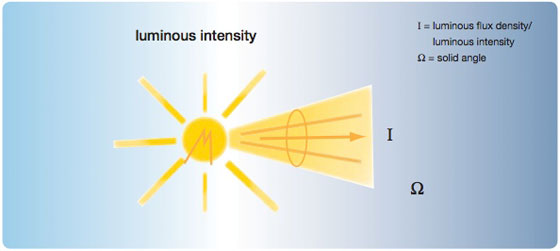
The luminous flux emitted by the light source illuminates the surfaces that it meets. The intensity with which the surfaces are illuminated is referred to as the degree of illumination. The degree of illumination depends on the magnitude of the luminous flux and the size of the surfaces.
It is defined as follows:
E = Φ/ A [lx=lm/m2]
E = degree of illumination
Φ = luminous flux in lm
A = illuminated surface
In accordance with the above table, a 100 W incandescent lamp with 15 lm/W generates a maximum luminous flux of 1500 lm. If the entire luminous flux of the incandescent lamp is not emitted in a spherical manner into the room, but rather concentrated and distributed evenly on a surface of 1 m2, then the value for the degree of illumination at every point on the surface would be 1500 lx.
The perceived brightness of an illuminated surface depends on the illuminated surface and the reflectance of the illuminated surfaces. The reflectance is the reflected share of the luminous flux from the illuminated surface. Typical values for the reflectance are:
- 90% highly polished silver
- 75% white paper
- 65% highly polished aluminium
- 20% – 30% wood
- < 5% black satin
The perceived brightness of an illuminated surface or a self-illuminating surface, e.g. an LCD monitor, is designated as the luminance. The unit of luminance is cd/m2.
If white paper is subject to a degree of illumination of 500 lx, then the luminance is about 130 – 150 cd/m2. At the same degree of illumination, environmentally-friendly paper has a luminance of about 90 – 100 cd/m2.
On what does the luminance measured by the light sensor respectively the measured value of the light sensor depend?
The luminance “primarily” detected by the light sensor depends on different criteria. It depends on the degree of illumination which the surfaces in the detection range of the light sensor are illuminated. The higher the degree of illumination, the higher the luminance of the illuminated surfaces.
The same applies for the reflectance of the surfaces. The higher the reflectance, the higher the luminance of the surfaces and thus the measured value of the sensor. The measured value of the sensor is the actual value used for lighting control.
The installed height of the sensor also plays a role. If the light sensor was an ideal “luminance measurement device”, then the luminance which it measures would be indepen- dent of the installation height of the light sensor. As this is not the case, the measured value of the sensor decreases as the installation height increases.
SOURCE: ABB | Practical Knowledge: ABB i-bus® KNX Constant lighting control
.
Related articles
- ABB launches new generation 420kV gas insulated switchgear
- ABB Power Transformers – A guide to manufacturing
- The New ETS4: Easy, Fast, Open
- An Example Of KNX Project Design
- Cost benefits of AC drives
5,716 views

ePlusMenuCAD 9 - Advanced Electrical Design Tool
ePlusMenuCAD 9 is finally released! Since version 3, ePlusMenuCAD has been changed and improved a lot, and now, version 9 is fine polished and most complete version so far.
There are many improvements and some new things that will be very usefull to designers.
Many electrical designers use AutoCAD platform in their daily work. ePlusMenuCAD is an integrated tool within AutoCAD which contains almost every aspect of electrical design.
Few Words About ePlusMenuCAD 9
ePlusMenuCAD is a software tool for professonal electrical design in AutoCAD environment. If you do electrical design using AutoCAD, then you certainly know how much time you lose on inserting varius blocks of luminaires, sockets, panels, generating technical specifications, drawing single line diagrams, etc.
If you use your own blocks in AutoCAD which are placed somewhere on your HDD and insert them when needed in the drawing, and after that manually copy each time – then ePlusMenuCAD is for you. All the symbols are placed in one place, available from the drop-down menu , 26 toolbars, and also from intuitive shorcuts from command line. No more boring inserting and copyng blocks! ePlusMenuCAD offers efficency and high speed in generating technical specifications for Bill of Quantities, as well as automation in inserting electrical symbols into drawing.
In ePlusMenuCAD there are two modules integrated: Mosaic Design and X-functions. Mosaic Design is advanced tool for creating single line diagrams and application diagrams. Large database of (universal) symbols covers almost any kind of scheme. Insertion of symbols and feeders, and generation of BOM is completely automated and very easy for use in drawing. Second module X-functions, has more than 50 extra usefull functions (commands) that saves a lot of time durin daily work in AutoCAD. Working with layers, blocks, polylines etc. is much much easier .
ePlusMenuCAD can be translated in to two languages English and Serbian/Croatian.
Example
Example of using ePlusMenuCAD in project Hotel Splendid in Budva (Montenegro), where it was used for designing lighting, power distribution, technology, installations of sockets and single line diagrams.


AutoCAD support
AutoCAD versions 2006, 2007, 2008, 2009 and 2010 are fully supported, and ePlusMenuCAD can be installed and used simultany on this versions. That means that ones ePlusMenuCAD is installed, you can use it in all (supported) installed AutoCAD versions.
Conception
")
ePlusMenuCAD drop-down menu (click to enlarge)
More than 1200 electrical symbols are placed in its categories (outlets, luminaires, types of installation, DEA, Cable verticals, labels of cables, transformers, cable feeds, TKS, EIB KONNEX ..). Every category has its layer. Layers carry the prefix “EnJS_” and “EnTS_” so that can be easily sorted in Layer Manager in the AutoCAD.
Also, there are a lot of various types of luminaires from metal-halid throug incadescent sorted by category and with predict shortcuts from the command line. Lamps that are designed to be supplied rom Diesel Agregate DEA, have cross symbol, and as such are also located in generated technical specification. Almost every area in which there are elements is covered with IEC symbols.
Drop-down menu is well organized, all symbols and functions are divided into categories, the most important are shown below:
Electrical distribution of power
• Predefined types of power supply lines (network, aggregate, UPS, diesel supply…)
• Power transformers – dry type and distribution oil transformers (with and without conservator) typical powers 630, 1000, 1600, 2000, 2500 and 3200kVA
• Distribution boards and panels, panels supplied from diesel agregate, and all with labels
• Cable or busbar vertical runs with their labels of incoming or outgoing connections
• Predefined labels for the cables in the colors (to distinguish cables of differnt type and supply…)
Installation of power sockets
• Power sockets 2P and 3P in the IEC variations and variations GOST standards (Russian standard)
• TV, antenna, computer plug and terminal space in the floor, fan-coil connection…
• Thermostats, rails for the main and additional equipotential deuce …
• Cable feeds for direct consumers, in wall and ceiling (2P, 3P), luminaires
Power and distribution transformers 10-20/0, 4kV
• Dry type transformer, powers: 630kVA – 3200kVA
• Oil type transformers, powers: 630kVA – 2500kVA with and without conservator
Installation of earthing
• Vertical runs of FeZn earthing bar (predefined in various colors)
• Tables for power sockets, cable feeds, lamps, and elements of Earthing with predefined default values
Legends
• Legends for the power sockets, luminaires, electric distribution and cables (2p and 3p)
• Stamp basis (the ability to post the logo of your company)
• Unique symbol of current round ECM
• The automatic marking ECM and (increasing, decreasing or all of the same series)
Installation of lighting
• Fluoroscent lamps built-in and built-on, powers from 1x18W to 4x36W with DEA symbols
• Fluroscent tubes, powers from 1x18W to 2x36W
• Fluo-compact lamps built-in and built-on, powers from 1x9W to 2x36W with DEA symbols
• Incadescent lamps, built-in and built-on, powers from 40W to 100W with DEA symbols
• Incadescent-reflect lamps, built-in and built-on, with DEA symbols
• Halogen lamps built-in and built-on, powers from 20W to 1000W with DEA symbols
• Metal-halid lamps built-in and built-on, powers from 70W do 2000W with DEA symbols
• Reflectors
• Crystal chandeliers for the salons and kitchen
• Decorative lamps for billiard tables, halls, theaters…
• Lamps for outdoor lighting (pillars, underwater lamps …)
• Anti-panic lamp
• Sensors and feeds the optical cable …
• Installation switches, 2p, 3p, alternate, serial …
• Dimers, tasters…
Telecommunications and signal systems
• predefined types of installations (fire, access control, anti-burglary, structural wiring…)
• Anti-burglary
• Anti-fire
• Access control
• Video surveillance – CCTV
• TV and Radio
• Phone and intercom
• Clock
• Gas
• Audio-Video Systems
• Speakers
• Power supply
• Wireless transfer of information
EIB KONNEX
• Instabus elements (system, input / output, lighting, heating / cooling, display, infrared …)
What can be designed with ePlusMenuCAD?
| Electric systems up to 1000V |
| √ Designing transformer substations 20/10/6/0,4 kV |
| √ Installations of power sockets (+ IEC symbols) |
| √ Installations of power distribution (+ cable labels) |
| √ Single line diagrams and application schemes of switchgears 0,4 kV |
| √ Reserv power supply (Diesel agregate, UPS system) |
| √ External cable distribution 20/10/6/0, 4 kV |
| √ Installation of interior lighting (general, technology and decorative) |
| √ Installation of external lighting (lighting roads, promenades, courts …) |
| √ Installation of lighting open trade centers and parking space |
| √ Installation of decorative lighting for public facilities and open sports facilities |
| √ Lightning protection |
| √ Earthing system |
| √ Technological installations |
| Telecommunications and signaling systems |
| √ Telephone system and installations |
| √ Intercom system and installations |
| √ Systems and installations for reception and distribution R / TV |
| √ Speaker systems |
| √ Anti-fire system and installations |
| √ Anti-burglary system and installations |
| √ Access control system |
| √ Hotel management system |
| √ Clock system |
| √ Conference system |
| √ Gas detection system |
| √ Wireless information transfer system |
Highlights:
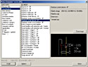 MOSAIC DESIGN: ePlusMenuCAD is fully capable to draw single line diagrams and application schemes using built-in modul Mosaic Design. Main feature is the fact that all pages of scheme are in one DWG drawing, and that user can create complete distributive or motor feeders in a minute, just by picking on one of the many predefined feeders.User can also plot one or one hunderd and one scheme just with one click. All elements and feeders are intuitive sorted in iNteLLi Elements, with options of zoom preview of each element or feeder. Mosaic Design runs when you open one of it’s templates from default folder (new drawing). There are several offered templates that are copied during installation of ePlusMenuCAD in default AutoCADs template folder. Now, all you have to do is to choose one template and Mosac Design module will be automatically loaded, and you can use any command from the menu or a toolbar. You can also simply change existing template and save it as your own template .
 SCALE FACTOR: All symbols (blocks) in ePlusMenuCAD are defined by ScaleFactor. This is the scale of symbols with respect to the drawing. Default value is 1, but it can be changed at any time to any positive value. Symbols of electric current mark ECM and tables of power sockets and luminaires have scale factor SFecm, and symbol of junction box has its scale factor SFjb. In this way, you can intelligently control the scale of symbols in the drawing. Scale can therefore be changed very easy. If you don’t want to think about the Scale Factor, then set the Master SF to some value that applies to all drawings.
 InfoIt PRO: Is a function to be used for generating Bill of Quantaties as well as for getting a lot of information about the symbols in the drawing. What can you do with InfoIt? You can take out a detailed technical specification from DWG drawing, calculate installed single-phase and three-phase el. powers of sockets and cable feeds from their tables, export report to MS Word, take out a list of all non-ePlusMenuCAD blocks, take out all luminaires by tags. InfoIt PRO is integrated part of ePlusMenuCAD. InfoIt Database is a unique datsbase of blocks that are within ePlusMenuCAD, and it offers the possibility to add your own symbol definitions – your own blocks . It is also possible to edit descriptions of all blocks in the InfoIt Database.
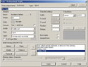 iNaLL Professional 6: A unique tool for every-day work in AutoCAD. It can make changes in the content of text objects TEXT, MTEXT, ATTRIBUTE, BLOCK, DIM. Inall PRO can store any text that you select into internal memory, so you can use it later in some other drawing. It has the support of the Serbian latin letters ČĆĐŠŽ, as well as all Russian letters, which can be used with any font. You can also import content of any text file into iNaLL PROs memory and use it for pasting in text objects in drawing.
Download link: Here
.
Related articles
- ePlusMenuCAD 10 RC1 – New Release
- UPS design criteria and selection
- What is PowerLogic System?
- Substation, Its Function And Types
- Shielding Of Power Cables
2,086 views
ABB - 10 Technical Guides
Na stranici ABB Technical Guides su postavljeni tehnički vodiči (eng. Technical Guides) koje je objavio proizvođač opreme ABB. Postavljeno je 10 tehničkih vodiča koji se uglavnom bave temom frekventnih regulatora, upravljanjem motorima i slično.
Pored tehničkih vodiča, tu su i uputstvo za ekstruder sa AC motorima i uputstvo za korišćenje frekventnih regulatora u aplikaciji sa pumpama. Na ovoj strani se nalazi i e-knjiga Technical guide book u kojoj je nalazi veliki broj odgovora na važna pitanja.
ABB Drives: Technical Guides
- Technical Guide 01 – Direct Torque Control
- Technical Guide 02 – EU Council Directives and adjustable speed electrical power drive .systems
- Technical Guide 03 – EMC compliant installation and configuration for a power drive .system
- Technical Guide 04 – Guide to Variable Speed Drives
- Technical Guide 05 – Bearing Currents in Modern AC Drive Systems
- Technical Guide 06 – Guide to Harmonics with AC Drives
- Technical Guide 07 -Dimensioning of a Drive system
- Technical Guide 08 -Electrical Braking
- Technical Guide 09 -Guide to motion control drives
- Technical Guide 10 -Functional safety
- Application Guide to extruders in AC drives
- Application Guide – Using variable speed drives (VSDs) in pump applications
- ABB Drives – Technical guide book
Link: ABB Technical Guides
.
Related articles
- Cost benefits of AC drives
- ABB launches new generation 420kV gas insulated switchgear
- ABB Power Transformers – A guide to manufacturing
- ABB Feeder Protection REF615 ANSI
- Motors for dusty, potentially explosive atmospheres
2,297 views

ePlusMenuCAD 9 padajući meni
ePlusMenuCAD je od verzije 3 pretrpeo puno izmena i poboljšanja. Nova verzija 9 predstavlja ispoliranu verziju sa zaista puno ispravljenih i poboljšanih funkcija.
Projektantima će sada biti na raspolaganju (pored proračuna pada napona i preseka kabla i fotometrijskog proračuna) i proračun zaštite od atmosferskog pražnjenja, tj. gromobranske zaštite, kao i nekoliko novih i korisnih funkcija kao što su de-instaler iz AutoCAD-a, CLO zatvaranje svih crteža, RAM standardni okvir za crteže…
Budući da je sa verzijom 9 postavljena i nova cena programa, svima koji su hteli da kupe licencu, CsanyiGroup nudi da do 15.12.2009 kupe licencu ePlusMenuCAD 9 po staroj ceni od 180EUR. Od ove verzije, nadogradnja tj. update na novu verziju je besplatan (u okviru iste verzije, 9).
Stara cena važi do 15.12.2009. Iskoristi priliku!
Par reči o ePlusMenuCAD 9:
Integriše unutar AutoCAD-a u obliku padajućeg menija, kao i 26 paleta sa alatima, tj. toolbar-ova koji se uključuju po potrebi. Svi simboli kojih ima preko 1200 se nalaze u svojim katergorijama (priključnice , osvetljenje, tipovi instalacija, DEA, vertikale, oznake kablova, transformatori, kablovski izvodi, TKS, EIB KONNEX ..), i kao takvi se nalaze u svojim lejerima. Lejeri nose prefix „EnJS_“ i „EnTS_“ tako da se lako sortiraju u Layer Manager-u u AutoCAD-u. Svi elementi u programu mogu biti u lejerima na srpskom ili engleskom jeziku u zavisnosti od potreba korisnika.
Verzije AutoCAD 2006, 2007, 2008, 2009 i 2010 su potpuno podržane i ePlusMenuCAD™ se može nesmetano instalirati i koristiti na ovim platformama. Jednom kada se instalira u Windows-u, ePlusMenuCAD™ se može koristiti istovremeno u svim podržanim verzijama AutoCAD-a koje imate instalirane na računaru.
Mogućnosti:
- 2 podržana jezika – srpski i engleski
- Proračun pada napona i potrebnog preseka kabla
- Fotometrijski proračun na crtežu
- Proračun zaštite od atmosferskog pražnjenja – gromobranska zaštita
- Jednopolne i šeme delovanja sa veikom bazom simbola i kompletnih distributivnih i motornih izvoda
- Detaljna tehnička specifikacija – generisanje izvešataja sa naprednim opcijama
- Energetski razvod (napajanje, mreža, agregat, UPS, transformatori, razvodni ormani …)
- Instalacije priključnica (2P i 3P priključnice, kablovski izvodi… u IEC i GOST standardima)
- Energetski i distributivni transformatori (suvi i uljni sa i bez konzervatora)
- Instalacije uzemljenja (Vertikale FeZn trake, var traka-traka…)
- Legende i pečat (predefinisane legende za en. razvod, priključnice, osvetljenje, strujni krug…)
- Instalacije osvetljenja (fluoroscentne, inkadescentne, halogene… sa svojim DEA simbolima…)
- Telekomunikacioni sistemi (protivprovala, protivpožar, kontrola pristupa, CCTV, ozvučenje…)
- Instabus elementi (sistem, input-output, lighting, heating/cooling, display, infrared …)
- Preko 100 jako korisnih funkcija za brži i automatizovani rad u AutoCAD-u
- Galerija opštih simbola (ljudi, kompjuterska oprema, paneli…)
Pored svih navedenih mogućnosti, insertovanje simbola je potpuno automatizovano i jednostavno. Praktično, projektant će dosta vremena uštedeti zahvaljujući tehnologiji insertovanja i generisanja izveštaja sa crteža. Velika paleta simbola u ePlusMenuCAD-u sigurno ispunjava i najveće zahteve projektanata.
Primer:
Primer korišćenja ePlusMenuCAD™-a na osnovama tehnologije, razvoda, priključnica, osvetljenja, gromobrana itd. Prikazani delovi osnova su iz projekta Hotel Splendid u Budvi – Crna Gora u kojem je korišćen ePlusMenuCAD za projektovanje el. instalacija.
ePlusMenuCAD – Korisni linkovi:
- Listing izmena u verziji 9 (Changelog)
- Detaljne informacije o ePlusMenuCAD-u
- Poručivanje licence za pravna lica
- Poručivanje licence za fizička lica
.
Related articles

Stručni tekst autora Dardan Klimenta, Viktor Kuč i Jordan Radosavljevic
U ovom radu su predstavljene mogućnosti nastanka kvarova kod podzemnih kablovskih vodova usled radova na uklanjanju korenja okolnog visokog rastinja i ukazano je na potrebu da se tehnički propisi koji se trenutno koriste u Republici Srbiji i Republici Crnoj Gori moraju dopuniti regulativama koje bi propisale načine polaganja kablova u blizini visokog rastinja.
Razmatrana problematika je ilustrovana na autentičnom primeru kvara koji se dogodio 14. novembra 2007. godine na podzemnom 0.4 kV-om kablovskom vodu instaliranom u Bijelom Polju u Republici Crnoj Gori. Simulacija nelinearne tranzijentne raspodele temperaturnog polja izvršena je pomoću softvera baziranog na metodi konačnih elemenata.
1. UVOD
Pojedina poglavlja kablovske tehnike postaju interesantna tek onda kada se u distributivnoj mreži ili u nekom od industrijskih ili elektroenergetskih postrojenja dogodi kvar. Tako je ovom prilikom u prvi plan izbio međusobni odnos podzemnih energetskih kablova i korenja visokog rastinja. U odsustvu domaćih propisa koji bi uredili ovu problematiku, bilo je pitanje vremena kada će se na nekom podzemnom kablovskom vodu dogoditi kvar izazvan dejstvom korenja. Kvar te vrste dogodio se 14. novembra 2007. godine na podzemnom 0.4 kV-nom kablovskom vodu koji povezuje transformatorsku stanicu 10/0.4 kV/kV ′′Bjelasica′′ i industrijsko postrojenje za proizvodnju mleka i mlečnih proizvoda A. D. Krisma Milk – Bijelo Polje u R. Crnoj Gori. Uticaj vegetacije na podzemne energetske kablove do sada nije značajnije diskutovan u domaćim i inostranim naučno- tehničkim krugovima. Ukoliko se to i događalo pokušaji su se svodili na merenje i izračunavanje specifičnog toplotnog otpora zemljišta duž kablovske trase radi konstatacije isušivanja zemljišta u blizini visokog rastinja [1,2].
Veliki broj IEEE publikacija kao što je [3] bavi se raspodelom temperaturnog polja i kretanjem vlage u okolini podzemnih kablovskih vodova ali ne i problematikom polaganja kablova u blizini visokog rastinja. IEC standardi koji propisuju postupke izračunavanja strujnih opterećenja kablova za različite uslove polaganja kablova takođe ne dotiču ovu problematiku [4-6]. Propisi EPS-a takođe ne regulišu način polaganja energetskih kablova u blizini visokog rastinja [7], ali se isti u domaćoj praksi polažu na najmanje 2 m od visokog rastinja, tj. od stabala drveća. Navedeno rastojanje je preuzeto iz internih propisa gradskog zelenila grada Beograda [9,10]. Međutim, propisi preduzeća koja se bave održavanjem gradskog zelenila mogu važiti samo za uslove izvođenja radova iz domena njihove delatnosti ali ne i za projektovanje kablovskih vodova zbog postojanja niza tehničkih faktora koji bi trebali biti obuhvaćeni njima a nisu.
U svetu nije retko iskustvo i da vlada neke države donese paket propisa koji u celosti uređuje ovu problematiku kao što je to učinilo Ministarstvo ekonomskog razvoja Novog Zelanda [8]. Tako prema [8] odstojanje korenja visokog rastinja od podzemnih kablovskih vodova ne može biti manje od 0.5 m. Ovo se u biti razlikuje od onoga što se radi u našoj praksi gde se može dogoditi da podzemni kablovski vod prođe i kroz gust splet korenja.
Nemački standardi nalažu da se kablovi polažu na 2.5 m od stabala drveća [10]. Ako se pomenuto rastojanje ne može ispoštovati onda se kablovi provlače kroz cevi koje se polažu bušenjem ili utiskivanjem [10]. Prema ruskoj literaturi predviđa se da ovo rastojanje iznosi 2 m, ali se ostavlja mogućnost da se u dogovoru sa nadležnom kompanijom ono može i smanjiti [10]. Nepostojanje domaćih propisa u ovoj oblasti, okolnosti nastanka razmatranog kvara i minoran broj publikacija na ovu temu u svetu, bili su povod za pisanje ovog rada i iniciranje dopune tehničkih propisa koji se koriste u elektroprivredama R. Srbije i R. Crne Gore.
2. FORMULACIJA PROBLEMA
Proboj jedne od faza podzemnog 0.4 kV- nog kablovskog voda koji je trasiran između TS 10/0.4 kV/kV ′′Bjelasica′′ i industrijskog postrojenja za proizvodnju mleka i mlečnih proizvoda A. D. Krisma Milk – Bijelo Polje dogodio se 14. novembra 2007. u 3 h i 15 min. Nastanku ovog kvara prethodili su neadekvatni ambijentni uslovi u zemljištu oko kabla i mehaničko oštećenje izolacije kabla. Razmatrani kabl je tipa PP 00-AS 4×120 mm2 i nazivnog napona 0.6/1 kV. Uzroke za loše ambijentne uslove u zemljištu i mehaničko oštećenje kabla ovom prilikom treba tražiti u: (i) nepostojanju propisa koji bi uredili problematiku polaganja kablova u blizini visokog rastinja, (ii) nepostojanju propisa koji bi definisali postupke uklanjanja visokog rastinja u blizini podzemnih instalacija i (iii) višednevnim padavinama koje su prethodile nastanku kvara.
Poznato je da visoko rastinje isušuje zemljište i otežava zadržavanje vlage u njemu. Prema vrednostima specifičnih toplotnih otpora zemljišta izmerenim na mestima gde kablovski vodovi prolaze pored visokog rastinja i gde nema vegetacije proizilazi da se ova prva mogu smatrati toplotno kritičnim već u nominalnim režimima eksploatacije kablova. Za delove trase u blizini visokog rastinja vrednosti specifičnih toplotnih otpora kablovske posteljice i okolnog zemljišta dostižu 2 °C⋅m/W i 4 °C⋅m/W, respektivno [1]. One su bile dvostruko veće od njima odgovarajućih vrednosti u oblastima bez vegetacije [1].
; T – stabla topole; K – mesto kvara; R – rezerva kabla dužine 5 m i dozvoljenog poluprečnika savijanja 0.8 m.")
Slika 1. Raspored stabala topole u odnosu na položaj trase podzemnog 0.4 kV-nog kablovskog voda, mesto kvara i zgradu postrojenja za proizvodnju mleka i mlečnih proizvoda A. D. Krisma Milk – Bijelo Polje. EK – energetski kabl tipa PP 00-AS 4×120 mm2, nazivnog napona 0.6/1 kV i ukupne dužine 293.5 m (sa rezervom); T – stabla topole; K – mesto kvara; R – rezerva kabla dužine 5 m i dozvoljenog poluprečnika savijanja 0.8 m.
Porast vrednosti specifičnog toplotnog otpora zemljišta jeste bitan termički aspekt eksploatacije podzemnih kablovskih vodova u blizini visokog rastinja ali ne i jedan od uzroka kvara na posmatranom 0.4 kV-nom kablovskom vodu. Ovom prilikom je interesantnije osvrnuti se na mehanička naprezanja i oštećenja kablova usled dejstva korenja visokog rastinja.
Pojedine vrste drveća imaju vrlo snažno i „agresivno“ (brzorastuće) korenje tako da se o tome mora voditi računa još u fazi projektovanja podzemnih kablovskih vodova. Izraziti predstavnici takvog drveća su topole koje su i uzrok ovde razmatranog kvara. Žile korena topole po horizontali se od svojih stabala udaljavaju i po više od 30 m [11]. Veličina i razvijenost korena topole zavise od faktora kao što su njena vrsta, starost, geografska zona i sl.
Raspored stabala topole u odnosu na položaj trase podzemnog 0.4 kV-nog kablovskog voda, mesto kvara i zgradu postrojenja prikazan je na slici 1. Današnja zgrada postrojenja do 1980. godine služila je drugoj nameni a električnom energijom je snabdevana preko danas nepostojećeg nadzemnog voda. Sa prilagođavanjem zgrade današnjim potrebama rešeno je da se pređe na napajanje preko podzemnog kablovskog voda koji bi po prenosnoj moći odgovarao potrošnji postrojenja.
Osnovni razlog zašto je ovaj kabl 1980. položen u zemljište gde se prepliće korenje topola starih po 41 godinu bilo je nepostojanje propisa koji bi to tada sprečio ili naložio da se to izvede na tehnički valjan način. Izuzev dubine polaganja na pojedinim mestima, svi ostali tehnički propisi, kao što su rezerva, vijuganje, poluprečnik savijanja, upozoravajuća traka i sl., ispoštovani su i prema danas vežećim propisima [4-7]. U prilog lošem izboru trase kabla tada je išla i činjenica da je ondašnji plan uređenja zelene površine ispred zgrade postrojenja predviđao i zadržavanje postojećeg drvoreda što se svakako pokazalo pogrešnim.
 polaganje kabla; b) ambijentni uslovi u zemljištu tokom perioda eksploatacije kabla bez oštećenja izolacije; c) radovi na uklanjanju vegetacije: sečenje stabala, vađenje panjeva i izravnanje terena; d) ambijentni uslovi u zemljištu tokom perioda eksploatacije kabla sa oštećenjem izolacije; e) periodične padavine.")
Slika 2. Hronološki prikaz radova i uslova koji su prethodili nastanku kvara na podzemnom 0.4 kV-nom kablovskom vodu. a) polaganje kabla; b) ambijentni uslovi u zemljištu tokom perioda eksploatacije kabla bez oštećenja izolacije; c) radovi na uklanjanju vegetacije: sečenje stabala, vađenje panjeva i izravnanje terena; d) ambijentni uslovi u zemljištu tokom perioda eksploatacije kabla sa oštećenjem izolacije; e) periodične padavine.
Na slici 2 dat je hronološki prikaz radova i uslova koji su prethodili nastanku kvara na podzemnom 0.4 kV-nom kablovskom vodu. Odstupanje od propisa na mestu kvara dogodilo se još u fazi polaganja kabla kada je isti položen direktno u zemlju na dubini od 0.5 m umesto na propisanih 0.7 m (slika 2a). Kabl je na ostatku trase položen na 0.7 m. Razlog za polaganje kabla na dubini različitoj od propisane bio je gust splet korenja na koji se tada naišlo prilikom iskopavanja rova.
Brz razvoj korenja doveo je do toga da je zemljište u kablovskom rovu već posle godinu dve bilo prožeto žilama korenja a kabl izložen mehaničkom naprezanju od strane njih (slika 2b).
Do mehaničkog oštećenja izolacije kabla dolazi 17. juna 2007. za vreme radova na uklanjanju vegetacije (slika 2c). Vađenje panjeva je izvršeno pomoću bagera i definitivno je uzrok oštećenja kabla. Prilikom izvlačenja jednog od panjeva čije je korenje obavijalo kabl neizbežno je došlo do zatezanja jedne žile korena, njenog usecanja u izolaciju kabla i konačno njenog kidanja.
Po vađenju panjeva, izravnavanju terena i nabijanju zemljišta, u periodu od 17. juna do 10. novembra 2007., imala se eksploatacija kabla sa mehanički oštećenom izolacijom u zemljištu gde je preostalo dosta pokidanih žila korenja (slika 3d). U tom periodu uticaj ionako malih padavina bio je zanemarljiv iz sledećih razloga: (i) u periodu od 01. juna do 30. septembra 2007. vršena je rekonstrukcija objekta i remont opreme tako da je postrojenje bilo van funkcije a kabl opterećen samo snagom osvetljenja objekta i električnih alata korišćenih tom prilikom i (ii) u periodu pogona postrojenja od 01. oktobra do 10. novembra 2007. nije bilo značajnijih padavina.
Period količinski značajnijih padavina počinje 10. novembra 2007. i nastavlja se sve do nastanka kvara na kablu 14. novembra 2007. (slika 2e).
3. MODELIRANJE I SIMULACIJA KVARA
Priprema modela konačnih elemenata za jedan nelinearni termodinamički sistem kao što je podzemni kabl pogođen jednofaznim zemljospojem nije nimalo lak zadatak. Za diskusiju u ovom radu od značaja će biti samo temperature provodnika i izolacije kabla ali ne i raspodela temperature u okolnom zemljištu tako da bi rešavani domen većih dimenzija bio suvišan. Izborom domena trakastog oblika koji bi obuhvatio poprečni presek kabla na mestu kvara i površinu zemlje kao granicu sa definisanim graničnim uslovom konvekcije otvara se mogućnost da se za proračun upotrebi nekomercijalna verzija softverskog paketa QuickField 5.5.
Naime, ovaj softverski alat ima ograničenje (postavljeno od strane proizvođača) i njime se unutar rešavanog domena ne može generisati mreža koja bi imala više od 255 čvorova. Umrežena geometrija rešavanog domena prikazana je na slici 3.

Slika 3. Umrežena geometrija poprečnog preseka rešavanog domena.
Za model konačnih elemenata sa slike 3 važi: (i) njegove spoljašnje dimenzije su 100 mm × 526 mm; (ii) sastoji se od 7 blokova: okolno zemljište, PVC izolacija, četiri aluminijumska provodnika i deo mehanički oštećene PVC izolacije; (iii) mreža ima ukupno 227 čvorova; (iv) poprečni preseci sektorskih provodnika kabla zamenjeni su njima ekvivalentnim okruglim provodnicima prečnika 12.4 mm; (v) konstruktivni podaci kabla sa ekvivalentnim provodnicima kružnog preseka su: debljina izolacije provodnik-provodnik 3.2 mm, debljina spoljašnjeg plašta 2.4 mm i spoljašnji prečnik kabla 41.5 mm; (vi) raspored provodnika u kablu izvršen je u smeru kretanja kazaljke na časovniku na sledeći način: faza A – faza B – faza C – neutralni provodnik, počevši sa provodnikom koji je najudaljeniji od površine zemlje; (vii) pretpostavljeno je da se mehaničko oštećenje izolacije dogodilo uz provodnik faze A; (viii) blok kojim je modelirano mesto mehaničkog oštećenja izolacije zasenčen je na slici i ima termofizičke karakteristike okolnog zemljišta.
Termofizičke karakteristike materijala date su u tabeli 1. Deo ovih karakteristika je nelinearan, odnosno zavisi od temperature.
![Tabela 1. Termofizičke karakteristike materijala. * Temperaturna zavisnost specifične električne otpornosti aluminijuma u Ω⋅m-1 definisana je izrazom (1). Ova kriva predstavlja aproksimaciju realne temperaturne zavisnosti toplotne provodnosti za materijal okolnog zemljišta. Aproksimacija ove krive izvršena je na osnovu samo dve poznate vrednosti toplotne provodnosti, i to za 2.5 i 1.429 W⋅°C-1⋅m-1 koje odgovaraju temperaturama 10 i 50 °C, respektivno [12]](http://www.csanyigroup.com/wp-content/uploads/posts/kvarovi%20podzemne/tabela-1.jpg "Tabela 1. Termofizičke karakteristike materijala. * Temperaturna zavisnost specifične električne otpornosti aluminijuma u Ω⋅m-1 definisana je izrazom (1). Ova kriva predstavlja aproksimaciju realne temperaturne zavisnosti toplotne provodnosti za materijal okolnog zemljišta. Aproksimacija ove krive izvršena je na osnovu samo dve poznate vrednosti toplotne provodnosti, i to za 2.5 i 1.429 W⋅°C-1⋅m-1 koje odgovaraju temperaturama 10 i 50 °C, respektivno [12]")
Tabela 1. Termofizičke karakteristike materijala. * Temperaturna zavisnost specifične električne otpornosti aluminijuma u Ω⋅m-1 definisana je izrazom (1). Ova kriva predstavlja aproksimaciju realne temperaturne zavisnosti toplotne provodnosti za materijal okolnog zemljišta. Aproksimacija ove krive izvršena je na osnovu samo dve poznate vrednosti toplotne provodnosti, i to za 2.5 i 1.429 W⋅°C-1⋅m-1 koje odgovaraju temperaturama 10 i 50 °C, respektivno [12
Specifična električna otpornost aluminijuma koja je u tabeli 1 označena sa NL-1 linearno se menja sa temperaturom θ prema izrazu:
Rp(θ)=Rp20(1+αAl(θ −20)) (1)
gde su
- Rp20 specifična električna otpornost aluminijuma na 20°C i
- αAl=0.004031 °C-1 temperaturni koeficijent promene električne otpornosti aluminijuma.
Za kabl tipa PP 00- AS 4×120 mm2, 0.6/1 kV , specifična električna otpornost Al-provodnika na 20 °C iznosi Rp20= 0.2547293 ⋅ 10-3 Ω⋅m-1.

Slika 4. Zavisnost toplotne provodnosti okolnog zemljišta normalne vlažnosti od temperature
U periodu obuhvaćenom simulacijom razmena toplote zračenjem na površini zemlje može se zanemariti jer je to bio period sa visokom relativnom vlažnošću vazduha. Takođe, u tom periodu nije bilo ni dejstva vetra pa se razmena toplote između površine zemlje i vazduha odvijala samo putem prirodne konvekcije. Prema [17] koeficijent razmene toplote konvekcijom je
h = 7.382 W/°C⋅m2, a srednja vrednost temperature vazduha u periodu simulacije bila je θe = 1.42 °C.
U postupku pripreme modela konačnih elemenata za nelinearnu tranzijentnu analizu procesa razmene toplote kod podzemnog kabla pogođenog jednofaznim zemljospojem poseban izazov predstavlja modeliranje izvora toplote lociranih u provodnicima kabla. Zbog složenosti termodinamike analiziranog problema ovde se uvodi niz pretpostavki koje će značajno pojednostaviti modeliranje izvora toplote. To su:
- početak simulacije odnosno početni trenutak numeričke integracije se poklapa sa početkom četvorodnevnog perioda sa periodičnim padavinama – u ponoć 09. novembra 2007. ili 0 s;
- u periodu pre početka simulacije kao i u trenutku t=0 s vrednost specifične električne otpornosti okolnog zemljišta Rz(θ) bila je dovoljno velika tako da na mestu kvara nije bilo struje kvara;
- tokom perioda pokrivenog simulacijom od 99 h i 19 min ili 357540 s smatra se da nije dolazilo do potpunog isušivanja okolnog zemljišta zbog padavina;
- vrednost specifične električne otpornosti okolnog normalno vlažnog zemljišta na mestu kvara Rz(θ) opada sa porastom temperature a njena maksimalna vrednost je Rz max = 20Ω⋅m i ima se za θ = 0 °C;
- kada je Rz(θ)=Rz max na mestu kvara protiče minimalna vrednost struje kvara Ik min ;
- minimalna vrednost specifične električne otpornosti okolnog normalno vlažnog zemljišta na mestu kvara Rz min je nepoznata a ima se za temperature θ ≥ θtd , gde je θtd = 160 °C dozvoljena temperatura PVC izolacije pri kratkom spoju za 0.6/1 kV-ne kablove sa provodnicima preseka do 300 mm2 [16];
- kada je Rz(θ)=Rzmin na mestu kvara protiče maksimalna vrednost struje kvara Ik max ;
- sistem trofaznih struja u kablovskom vodu pre kvara bio je simetričan a stvarni dnevni dijagrami opterećenja kabla tokom perioda numeričke integracije ekvivalentirani su srednjim dnevnim opterećenjem Idsr = 130.04 A;
- struja kvara se na mestu kvara u opsegu temperatura 0 ≤ θ ≤ θtd prema
 (2)
(2)
gde je θtp= 658°C temperatura topljenja aluminijuma, dok se za θ > θtd ima struja kvara:
Ik (θ) = Ik max (3)
gde je vrednost Ik max= 1272.632 A dobijena putem klasičnog proračuna struje kvara na osnovu podataka o industrijskom postrojenju instalisane snage 110 kW i faktora snage cosφ = 0.88 (postrojenje čini 31 asinhroni motor sa namotajima vezanim u trougao ukupne snage 106.1 kW dok ostatak instalisane snage ide na elektrootporne potrošače [13]), podataka o transformatoru (tipska oklopljena transformatorska stanica 10/0.4 kV/kV nazivne snage 630 kVA [7,14]) i kataloških podataka o kablu [2,10,15,16].
(x) na osnovu proračuna raspodele struje kvara po faznim provodnicima kabla od transformatora ka mestu kvara za vreme kvara proticale su struje čiji su moduli:
IAk =0.965⋅Ik max
IBk =ICk =0.023⋅Ik max (4)
na osnovu čega se, a s obzirom na (2) i (3), mogu proceniti struje merodavne za zagrevanje faznih provodnika za vreme trajanja kvara kao:
IAk(θ )=0.965 ⋅ Ik(θ ) + Idsr
IBk(θ )=ICk(θ )=0 .023 ⋅ Ik(θ ) + Idsr ( 5 )
Na osnovu prethodno uvedenih pretpostavki i izraza (1) zapreminske snage toplotnih izvora (u W/m3) lociranih u faznim provodnicima kabla postaju:
QAV(θ)=RP(θ)⋅IAK2(θ)/SP
QBV(θ)=RP(θ)⋅IBK2(θ)/SP
QCV(θ)=RP(θ)⋅ICK2(θ)/SP
gde je Sp površina poprečnog preseka jednog provodnika u m2. Džulovih gubitaka u neutralnom provodniku praktično nema zato što su na strani postrojenja svi asinhroni motori vezani u trougao. Dielektrični gubici u PVC izolaciji kabla su zanemarljivi iz razloga što je nazivni napon mreže 0.4 kV.
Da bi se zaključila priča o izvorima toplote u provodnicima kabla neophodno je još definisati postupak za procenu minimalne vrednosti specifične električne otpornosti okolnog normalno vlažnog zemljišta na mestu kvara Rz min. Procena vrednosti za Rz min vrši se iz razloga što ne postoji način da se na mestu kvara za vreme trajanja kvara utvrdi sadržaj vlage od kojeg Rz min zavisi. Takođe, za Rz min ne može se uzeti bilo koja vrednost otpornosti koja je znatno manja od 20 Ω⋅m iz razloga što bi se onda proboj provodnika faze A dogodio u nekom trenutku različitom od 3 h i 15 min koji je snimljen 14. novembra 2007.
Procena vrednosti za Rz min izvedena je pod pretpostavkom da je struja kvara na mestu kvara dostigla vrednost Ik max tek pri temperaturi provodnika faze A jednakoj θtd . Ova pretpostavka je fizički neverovatna zbog toga što je PVC izolacija u nužnom pogonu praktično termički nepreopteretljiva [10] ali u korist nje ide činjenica da se tokom posmatranog četvorodnevnog perioda imalo obnavljanje vlage u okolnom zemljištu pa se i moglo pretpostaviti da je kabl mogao raditi na temperaturama većim od trajno dozvoljene koja za ovaj kabl iznosi 70 °C.

Slika 5. Stacionarna raspodela temperature za režim rada neposredno pre početka perioda sa padavinama – početni uslovi za potrebe nelinearne tranzijentne analize.
Za procenu Rz min najpre treba odrediti početne uslove, tj. stacionarnu raspodelu temperature za režim rada neposredno pre početka perioda sa padavinama. Stacionarna raspodela temperature sa slike 5 izračunata je za simetričan sistem trofaznih struja IA, IB , IC kojima respektivno odgovaraju snage QAV = QBV = QCV = 40237.4 W/m3. Zatim se u prvom koraku proizvoljno izabira vrednost Rz min = 1 Ω⋅m za koju se dobija temperatura provodnika faze A θA <θtd ; ovo znači da u drugom koraku treba izabrati vrednost veću od 1 Ω⋅m. U drugom koraku izabira se vrednost Rz min = 2 Ω⋅m za koju se dobija θA >>θtd ; ovo znači da u trećem koraku treba izabrati vrednost između 1 i 2 Ω⋅m. Treći korak se započinje sa Rz min = 1.5 Ω⋅m i na isti način se (po principu metode polovljenja intervala) u 11. koraku dolazi do konačne vrednosti od Rz min = 1.205 Ω⋅m za koju temperatura provodnika faze A postaje θA =θtd .
Rezultati nelinearne tranzijentne analize dati su na slikama 6, 7, 8, 9 i 10. Na slikama 6, 7, 8 i 9 prikazani su tranzijenti zagrevanja provodnika faza A, B, C i neutralnog provodnika, respektivno. Svi prikazani tranzijenti zagrevanja provodnika kabla snimljeni su u centrima njima odgovarajućih kružnica. Na slici 10 prikazan je tranzijent zagrevanja PVC izolacije u toplotno najkritičnijoj tački izolacije kabla, tj. centru kružnice kojom je predstavljena spoljašnja površina kabla.

Slike 6, 7, 8, 9 i 10 (klikni da uvećaš)
Interesantno je pogledati i raspodelu temperature po rešavanom domenu koja se dobija posle 5959. koraka nelinearne tranzijentne analize.
Ovaj korak numeričke integracije odgovara 5959. minutu u kojem temperatura provodnika faze A premašila temperaturu topljenja aluminijuma (prekid provodnika faze A), tj. 14. novembru 2007. u 3 h i 19 min.
Zapaža se da se numerički dobijen trenutak prekida faze A razlikuje za nešto manje od 4 minuta u plusu u odnosu na registrovani.
Raspodela temperature posle 5959. koraka numeričke integracije u vremenu prikazana je na slici 11.
4. NACRT TEHNIČKE PREPORUKE
Tehnička preporuka na osnovu koje bi se ubuduće mogla vršiti prevencija nastanka štete na podzemnim kablovskim vodovima usled dejstva vegetacije ili usled radova na njenom održavanju i uklanjanju treba prepoznavati subjekte kao što su:
- vlasnik drveta,
- preduzeće zaduženo za održavanje gradskog zelenila,
- elektrodistributivno preduzeće zaduženo za održavanje energetskih vodova,
- preduzeća zadužena za postavljanje i održavanje podzemnih instalacija druge vrste (vodovoda, gasovoda, toplovoda, kanalizacije i dr.), i
- nadzorni organ zadužen za implementaciju tehničkih preporuka pri radovima bilo koje vrste na i u blizini podzemnih energetskih kablova.
Za imenovanjem subjekata (fizičkih i pravnih lica) koji bi se mogli naći u eventualnom sporu oko naknade štete nastale na podzemnom kablovskom vodu usled dejstva vegetacije ili usled radova na njenom održavanju i uklanjanju u ovoj tehničkoj preporuci treba definisati ili obuhvatiti:
- najmanja dozvoljena odstojanja podzemnih kablova od korenja drveća s aspekta termičkih (isušivanje zemljišta) i
mehaničkih naprezanja, - metode polaganja kablova u zemljište za slučaj kada nije moguće izbeći korenje drveća ili ukloniti ga (skučen gradski prostor),
- metodu detekcije korenja pomoću zemno-dubinskog radara radi njihovog zaobilaženja još u fazi projektovanja trase kabla ili radi zaštite biljke od eventualnog presecanja vitalnih žila korena [18],
- obaveze, poslove i odgovornost vlasnika drveta,
- nadležnost, poslove, procedure izvođenja poslova i odgovornost preduzeća zaduženog za održavanje gradskog zelenila,
- nadležnost, poslove, procedure izvođenja poslova i odgovornost elektrodistribu- tivnog preduzeća,
- nadležnost, poslove, procedure izvođenja poslova i odgovornost preduzeća zaduženog za postavljanje i održavanje podzemnih instalacija druge vrste, i
- nadležnost i metode nadgledanja od strane nadzornog organa.
Od ispred navedenog, u tehničkom pogledu najznačajnije su stavke koje se odnose na projektovanje delova trase kabla koji bi mogli proći blizu visokog rastinja. Da bi se ove stavke usaglasile sa već postojećim u svetu potrebno je definisati pojas zabranjenog rasta (PZR) za korenje drveća. PZR je najmanje dozvoljeno rastojanje nekog drveta ili njegovog dela od nadzemnog voda ili podzemnog kabla [8].
Na osnovu domaće i strane prakse, u fazi projektovanja podzemnih kablovskih vodova treba se pridržavati sledećih preporuka:
- najveći nedostatak vlage u zemljištu se ima u zoni korenja visokog rastinja [2]; zona do koje dopiru žile korena nekog drveta je oblika kružnice sa centrom u njegovom stablu i poluprečnikom koji je jednak visini tog stabla [2]; vrednosti specifičnog toplotnog otpora u ovim zonama su i do dva puta veće od njima odgovarajućih vrednosti u oblastima bez vegetacije [1];
- PZR za korenje drveća u blizini podzemnih energetskih kablova iznosi 0.5 m [8];
- ukoliko trasa kabla mora proći kroz sistem korena nekog drveta onda u kablovskom rovu, i sa leve i sa desne strane projektovane trase, u zoni jednakoj 2⋅PZR, treba preseći i ukloniti sve delove korena [8]; u takvoj zoni kabl treba provući i kroz plastičnu cev zadovoljavajuće debljine zida cevi kako rast korena u budućnosti ne bi mehanički oštetio kabl (zaključak izveden na osnovu analize kvara razmatranog u ovom radu);
- ukoliko bi iskopavanje kablovskog rova moglo ugroziti neko drvo kidanjem vitalnih delova njegovog korena, a kabl mora proći upravo tuda, onda treba izvršiti precizno lociranje korenja pomoću radara za zemno-dubinsko snimanje i kabl provući kroz cev (zadovoljavajuće debljine zida cevi);
- ukoliko se ne poseduje radar za zemno- dubinsko snimanje, a kabl opet mora proći kroz splet korenja i najverovatnije ugroziti drvo, onda kabl treba položiti u cev (zadovoljavajuće debljine zida cevi) koja se polaže bušenjem ili utiskivanjem na 2-2.5 m od stabla drveta.
5. ZAKLJUČAK
Uz nacrt tehničke preporuke koja bi trebala postati sastavni deo propisa elektrodistributivnih preduzeća R. Srbije i R. Crne Gore, ovde je predstavljen i jedan novi pristup u modeliranju zagrevanja elemenata konstrukcije podzemnih energetskih kablova tokom zemljospojeva. Predloženi model možda i nije dao rezultate koji najvernije oslikavaju termodinamiku razmatranog kvara ali je zacelo novitet u odnosu na dosadašnju praksu proračuna baziranu na pretpostavci adijabatskog zagrevanja provodnika kabla pogođenog kvarom.
Posebno je značajna činjenica da bi ovde razrađeni model mogao dati još verniju sliku analizirane termodinamike kvara kada bi se znale tačne temperaturne zavisnosti termofizičkih karakteristika materijala zastupljenih u modelu.
AUTORI STRUČNOG TEKSTA: Dardan Klimenta, Viktor Kuč i Jordan Radosavljevic
.
Related articles
- No related posts found
25,642 views

8DN8 switchgear for rated voltages up to 145 kV
A fundamental feature of Siemens gas-insulated switchgear is the high degree of versatility provided by its modular system. Depending on their respective functions, the components are housed either individually and/or combined in compressed gas-tight enclosures. With a remarkably small number of active and passive modules, all customary circuit variants are possible. Sulphur hexafluoride (SF6) is used as the insulating and arc-quenching medium.
Three-phase enclosures are used for type 8DN8 switchgear in order to achieve extremely low component dimensions. This concept allows a very compact design with reduced space requirement. Aluminium is used for the enclosure. This assures freedom from corrosion and results in low weight of the equipment. The use of modern construction methods and casting techniques allows optimizing the enclosure’s dielectric and mechanical character- istics. The low bay weight ensures minimal floor loading and eliminates the need for complex foundations.
All the modules are connected to one another by means of flanges. The gastightness of the flange connections is assured by proven O-ring seals. Temperature-related changes in the length of the enclosure and installation tolerances are compensated by bellows-type expansion joints. To that end, the conductors are linked by coupling contacts. Where necessary, the joints are accessible via manway openings.
Gas-tight bushings allow subdivision of the bay into a number of separate gas compartments. Each gas compartment is provided with its own gas monitoring equipment, a rupture diaphragm, and filter material. The static filters in the gas compartments absorb moisture and decomposition products. The rupture diaphragms prevent build-up of an im- permissible high pressure in the enclosure. A gas diverter nozzle on the rupture diaphragm ensures that the gas is expelled in a defined direction in the event of bursting, thus ensuring that the operating personnel is not endangered.

Three-phase enclosure allows compact design

8DN8 switchgear parts (click to see large)
Circuit-breaker module
The central element of the gas-insulated switchgear is the three-pole circuit-breaker module enclosure comprising the following two main components:
- Interrupter unit
- Operating mechanism
The design of the interrupter unit and of the operating mechanism is based on proven and in most cases identical designs, which have often been applied for outdoor switchgear installations.
Operating mechanism
The spring-stored energy operating mechanism provides the force for opening and closing the circuit-breaker. It is installed in a compact corrosion- free aluminium housing. The closing spring and the opening spring are arranged so as to ensure good visibility in the operating mechanism block. The entire operating mechanism unit is completely isolated from the SF6 gas compartments. Anti-friction bearings and a maintenance-free charging mechanism ensure decades of reliable operation.
Proven design principles of Siemens circuit-breakers are used, such as vibration-isolated latches and load-free decoupling of the charging mechanism. The operating mechanism offers the following advantages:
- Defined switching position which is securely maintained even if the auxiliary power supply fails
- Tripping is possible irrespective of the status of the closing spring
- High number of mechanical operations
- Low number of mechanical parts
- Compact design
Three-position switching device

Positions
The functions of a disconnector and an earthing switch are combined in a three-position switching device. The moving contact either closes the isolating gap or connects the high-voltage conductor to the fixed contact of the earthing switch. Integral mutual inter- locking of the two functions is achieved as a result of this design, thus obviating the need for providing corresponding electrical interlocking within the switchgear bay. An insulated connection to the fixed contact of the earthing switch is provided outside the enclosure for test purposes. In the third neutral position neither the disconnector contact nor the earthing switch contact is closed. The three poles of a bay are mutually coupled and all the three poles are operated at once by a motor. Force is transmitted into the enclosure via gas-tight rotating shaft glands. The check-back contacts and the on-off indicators are mechanically robust and are connected directly to the operating shaft. Emergency operation by hand is possible. The enclosure can be provided with inspec- tion windows, in the case of which the “On” and “Off” position of all three phases is visible.
Outgoing feeder module
The outgoing feeder module connects the basic bay with various termination modules (for cable termi- nation, overhead line termination and transformer termination). It contains a three-position switching device, which combines the functions of an outgoing feeder disconnector and of a bay-side earthing switch (work-in-progress type). Installation of a high-speed earthing switch and of a voltage transformer is also possible where required. The high-voltage site testing equipment is generally connected to this module.
Busbar module
Connections between the bays are effected by means of busbars. The busbars of each bay are enclosed. Adjacent busbar modules are coupled by means of expansion joints. The module contains a three-position switching device, which combines the functions of a busbar disconnector and of a bay-side earthing switch (work-in-progress type).
Bus sectionalizers
Bus sectionalizers are used for isolating the busbar sections of a substation. They are integrated in the busbar in the same manner as a busbar module. The module contains a three-position switching device, which combines the functions of a bus sectionalizer and of an earthing switch (work-in-progress type).
High-speed earthing switch
The high-speed earthing switch used is of the so-called “pin-type”. In this type of switch, the earthing pin at earth potential is pushed into the tulip-shaped fixed contact. The earthing switch is equipped with a spring-operated mechanism, charged by an electric motor.
Proven switchgear control
All the elements required for control and monitoring are accommodated in a decentralized arrangement in the high-voltage switching devices. The switching device control systems are factory-tested and the switchgear is usually supplied with bay-internal cabling all the way to the integrated local control cubicle. This minimizes the time required for com- missioning and reduces the possibilities of error.
By default, the control and monitoring system is implemented with electromechanical components. Alternatively, digital intelligent control and pro- tection systems including comprehensive diagnos- tics and monitoring functions are available. More detailed information on condition of the substation state permits condition-based maintenance. This consequently reduces life cycle costs even further.
Gas monitoring
Each bay is divided into functionally distinct gas compartments (circuit-breaker, disconnector, voltage transformer, etc.). The gas compartments are con- stantly observed by means of density monitors with integrated indicators; any deviations are indicated
as soon as they arrive at the defined response thresh- old. The optionally available monitoring system includes sensors that allow remote monitoring and trend forecasts for each gas compartment.
Flexible and reliable protection in bay and substation control
Control and feeder protection are generally accom- modated in the local control cubicle, which is itself integrated in the operating panel of the switchgear bay. This substantially reduces the amount of time and space required for commissioning. Alternatively, a version of the local control cubicle for installation separate from the switchgear is available. Thus, different requirements with respect to the arrange- ment of the control and protection components are easy to meet. The cabling between the separately installed local control cubicle and the high-voltage switching devices is effected via coded plugs, which minimizes both the effort involved and the risk of cabling errors.
Of course we can supply high-voltage switchgear with any customary bay and substation control equipment upon request. We provide uniform systems to meet your individual requirements.

Left: Spring-stored energy operting mechanism; Right: Integrated local control cubicle
Neutral interfaces in the switchgear control allow interfacing
- conventional control systems with contactor interlocking and control panel
- digital control and protection comprising user- friendly bay controllers and substation auto- mation with PC operator station (HMI)
- intelligent, uniformly networked digital control and protection systems with supplementary monitoring and telediagnostics functions.
Given the wide range of Siemens control and protection equipment, we can provide customized concepts with everything from a single source.
Technical Data
| .Switchgear type | .8DN8 |
| .Rated voltage | .72.5 / 145 kV |
| .Rated frequency | .50 / 60 Hz |
| .Rated power frequency withstand voltage (1 min) | .140 / 275 kV |
| .Rated lightning impulse withstand voltage (1.2/50 μs) | .325 / 650 kV |
| .Rated normal current busbar .Rated normal current feeder | .2500 / 3150 A .2500 / 3150 A |
| .Rated short-breaking current | .31.5 / 40 kA |
| .Rated peak withstand current | .85 / 108 kA |
| .Rated short-time withstand current | .31.5 / 40 kA |
| .Leakage rate per year and gas compartment | .≤ 0.5 % |
| .Bay width | .650/800/1200 mm |
| .Height, depth | .see typical bay arrangements |
| .Driving mechanism of circuit-breaker | .stored-energy spring |
| .Rated operating sequence | .O-0.3 s-CO-3 min-CO .CO-15 s-CO |
| .Rated supply voltage | .60 to 250 V DC |
| .Expected lifetime | .> 50 years |
| .Ambient temperature range | .–30 / –25 °C up to +40 °C |
| .Standards | .IEC / IEEE |
Operation and maintenance
Siemens gas-insulated switchgear is designed and manufactured so as to achieve an optimal balance of design, materials used and maintenance required. The hermetically-sealed enclosures and automatic monitoring ensure minimal switchgear mainte- nance: The assemblies are practically maintenance- free under normal operating conditions. We re- commend that the first major inspection be carried out after 25 years.
.
Related articles
- ABB launches new generation 420kV gas insulated switchgear
- Substation, Its Function And Types
- Arc-resistant low voltage switchgear
- Air Insulated Substations – Bus/Switching Configurations
- MV-LV Transformer Substations Short Circuits
31,716 views

Designing a quality grounding system is not only for the safety of employees but also provides the protection required for buildings and equipment.
Ungrounded systems may provide greater continuity of operations in the event of a ground fault. However, the second fault will most likely be more catastrophic than a grounded system fault. Whenever ungrounded systems are used in a facility, the maintenance personnel should receive training in how to detect and troubleshoot the first ground on an ungrounded system.
Electrical systems can be operated grounded or ungrounded, depending on the condition of the systems use. Electrical systems are grounded to protect circuits, equipment, and conductor enclosures from dangerous voltages and personnel from electrical shock. See NEC Sections 110-9, 110-10, 230-65, 250-1, and 250-2 that list the requirements to provide this protection.
“Grounded” means that the connection to ground between the service panel and earth has been made. Ungrounded electrical systems are used where the designer does not want the overcurrent protection device to clear in the event of a ground fault.
Ground detectors can be installed per NEC Section 250-5(b) FPN to sound an alarm or send a message to alert personnel that a ground fault has occurred on one of the phase conductors. Ground detectors will detect the presence of leakage current or developing fault current conditions while the system is still energized and operating. By warning of the need to take corrective action before a problem occurs, safe conditions can usually be maintained until an orderly shutdown is implemented.
Grounded Systems
Grounded systems are equipped with a grounded conductor that is required per NEC Section 250- 23(b) to be run to each service disconnecting means. The grounded conductor can be used as a current-carrying conductor to accommodate all neutral related loads. It can also be used as an equipment grounding conductor to clear ground faults per NEC Section 250-61(a).
A network of equipment grounding conductors is routed from the service equipment enclosure to all metal enclosures throughout the electrical system. The equipment grounding conductor carries fault currents from the point of the fault to the grounded bus in the service equipment where it is transferred to the grounded conductor. The grounded conductor carries the fault current back to the source and returns over the faulted phase and trips open the overcurrent protection device.
Note: A system is considered grounded if the supplying source such as a transformer, generator, etc., is grounded, in addition to the grounding means on the supply side of the service equipment disconnecting device per NEC Sections 250-23(a) or 250-26 for seperately derived systems.
The neutral of any grounded system serves two main purposes: (1) it permits the utilization of line- to-neutral voltage and thus will serve as a current-carrying conductor to carry any unbalanced current, and (2) it plays a vital role in providing a low-impedance path for the flow of fault currents to facilitate the operation of the overcurrent devices in the circuit. (See picture below).
Consideration should be given to the sizing of the neutral conductor for certain loads due to the presence of harmonic currents (See NEC Sections 210-4 and 310-10).
 conductor routed between the supply transformer and the service equipment.")
A grounded system is equipped with a grounded (neutral) conductor routed between the supply transformer and the service equipment.
Ungrounded Systems
Ungrounded systems operate without a grounded conductor. In other words, none of the circuit conductors of the electrical system are intentionally grounded to an earth ground such as a metal water pipe, building steel, etc. The same network of equipment grounding conductors is provided for ungrounded systems as for solidly grounded electrical systems. However, equipment grounding conductors (EGCs) are used only to locate phase-to-ground faults and sound some type of alarm.
Therefore, a single sustained line-to-ground fault does not result in an automatic trip of the overcurrent protection device. This is a major benefit if electrical system continuity is required or if it would result in the shutdown of a continuous process. However, if an accidental ground fault occurs and is allowed to flow for a substantial time, overvoltages can develop in the associated phase conductors. Such an overvoltage situation can lead to conductor insulation damage, and while a ground fault remains on one phase of an ungrounded system, personnel contacting one of the other phases and ground are subjected to 1.732 times the voltage they would experience on a solidly neutral grounded system. (See picture below).
Note: All ungrounded systems should be equipped with ground detectors and proper maintenance applied to avoid, as far as practical, the overcurrent of a sustained ground fault on ungrounded systems. If appropriate maintenance is not provided for ungrounded systems, a grounded system should be installed to ensure that ground faults will be cleared and the safety of circuits, equipment, and that personnel safety is ensured.
 conductor routed between the supply transformer and the service equipment because the supply transformer is not earth grounded.")
An ungrounded system does not have a grounded (neutral) conductor routed between the supply transformer and the service equipment because the supply transformer is not earth grounded.
High impedance grounding
Electrical systems containing three-phase, three-wire loads, as compared to grounded neutral circuit conductor loads, can be equipped with a high-impedance grounded system. High-impedance grounded systems shall not be used unless they are provided with ground fault indicators or alarms, or both, and qualified personnel are available to quickly locate and eliminate such ground faults.
Ground faults must be promptly removed or the service reliability will be reduced. See NEC Section 250-27 for requirements pertaining to installing a high-impedance grounding system. (See picture below).
 conductor and the grounding electrode conductor, which is used to regulate fault current.")
A high-impedance grounding system has a high-impedance unit, installed between the grounded (neutral) conductor and the grounding electrode conductor, which is used to regulate fault current.
Source: DOE HANDBOOK – ELECTRICAL SAFETY
.
Related articles
- Shielding Of Power Cables
- ABB Feeder Protection REF615 ANSI
- Line Protection With Distance Relays
- UPS design criteria and selection
- Arc-resistant low voltage switchgear

Motor Operation Efficiency Under Abnormal Conditions
Operation under unusual service conditions may result in efficiency losses and the consumption of additional energy. Both standard and energy-efficient motors can have their efficiency and useful life reduced by a poorly maintained electrical system. Monitoring voltage is important for maintaining high-efficiency operation and correcting potential problems before failures occur.
Preventative maintenance personnel should periodically measure and log the voltage at a motor’s terminals while the machine is fully loaded.
Motors must be properly selected according to known service conditions. Usual service conditions, defined in NEMA Standards Publication MG1-1987, Motors and Generators, include:
- Exposure to an ambient temperature between 0°C and 40°C
- Installation in areas or enclosures that do not seri- ously interfere with the ventilation of the machine
- Operation within a tolerance of ± 10 percent of rated voltage
- Operation from a sine wave voltage source (not to ex- ceed 10 percent deviation factor)
- Operation within a tolerance of ± 5 percent of rated frequency
- Operation with a voltage unbalance of 1 percent or less
Over Voltage
As the voltage is increased, the magnetizing current increases by an exponential function. At some point, depending upon design of the motor, saturation of the core iron will increase and overheating will occur. At about 10 to 15 percent over voltage both efficiency and power factor significantly decrease while the full-load slip decreases. The starting current, starting torque, and breakdown torque all significantly increase with over voltage conditions.
A voltage that is at the high end of tolerance limits frequently indicates that a transformer tap has been moved in the wrong direction. An overload relay will not recognize this overvoltage situation and, if the voltage is more than 10 percent high, the motor can over-heat. Over voltage operation with VAR currents above acceptable limits for extended periods of time may accelerate deterioration of a motor’s insulation.
Under Voltage
If a motor is operated at reduced voltage, even within the allowable 10 percent limit, the motor will draw in- creased current to produce the torque requirements imposed by the load. This causes an increase in both stator and rotor I²R losses. Low voltages can also prevent the motor from developing an adequate starting torque. The effects on motor efficiency, power factor, RPM, and current from operating outside nominal design voltage are indicated in the diagram below.

Voltage Variation Effects on Motor Performance
.
Reduced operating efficiency because of low voltages at the motor terminals is generally due to excessive voltage drops in the supply system. If the motor is at the end of a long feeder, reconfiguration may be necessary. The system voltage can also be modified by:
- Adjusting the transformer tap settings
- Installing automatic tap-changing equipment if sys- tem loads vary considerably over the course of a day
- Installing power factor correction capacitors that raise the system voltage while correcting for power factor
Since motor efficiency and operating life are degraded by voltage variations, only motors with compatible voltage nameplate ratings should be specified for a system.
For example, three-phase motors are available with voltage ratings of 440, 460, 480, and 575 volts. The use of a motor designed for 460-volt service in a 480-volt system results in reduced efficiency, increased heating, and reduced motor life. A 440-volt motor would be even more seriously affected.
Phase Voltage Imbalance
A voltage imbalance occurs when there are unequal voltages on the lines to a polyphase induction motor. This imbalance in phase voltages also causes the line currents to be out of balance. The unbalanced currents cause torque pulsations, vibrations, increased mechanical stress on the motor, and overheating of one and possibly two phase windings. This results in a dramatic increase in motor losses and heat generation, which both decrease the efficiency of the motor and shorten its life.
Voltage imbalance is defined by NEMA as 100 times the maximum deviation of the line voltage from the average voltage on a three-phase system divided by the average voltage. For example, if the measured line voltages are 462, 463, and 455 volts, the average is 460 volts. The voltage imbalance is:
 A voltage unbalance of only 3.5 percent can increase motor losses by approximately 20 percent. Imbalances over 5 percent indicate a serious problem. Imbalances over 1 percent require derating of the motor, and will void most manufacturers’ warranties. Per NEMA MG1-14.35, a voltage imbalance of 2.5 percent would require a derate factor of 0.925 to be applied to the motor rating. Derating factors due to unbalanced voltage for integral horsepower motors are given in the diagram below. The NEMA derating factors apply to all motors. There is no distinction between standard and energy-efficient motors when selecting a derate factor for operation under voltage unbalance conditions.

Motor Derating due to Voltage Unbalance
Common causes of voltage unbalance include:
- Faulty operation of automatic power factor connection equipment
- Unbalanced or unstable utility supply
- Unbalanced transformer bank supplying a three-phase load that is too large for the bank
- Unevenly distributed single-phase loads on the same power system
- Unidentified single-phase to ground faults
- An open circuit on the distribution system primary
The following steps will ensure proper system balancing:
- Check your electrical system single-line diagram to verify that single-phase loads are uniformly distributed
- Regularly monitor voltages on all phases to verify that a minimum variation exists
- Install required ground fault indicators
- Perform annual thermographic inspections
.
Related articles
- General about motors
- Cost benefits of AC drives
- The Best Applications For VFDs
- The Benefits of VFDs In HVAC Systems
- Short Circuit Current Calculator & Group Motor Protection
31,022 views

Power transformer
In a real transformer, some power is dissipated in the form of heat. A portion of these power losses occur in the conductor windings due to electrical resistance and are referred to as copper losses. However, so-called iron losses from the transformer core are also important. The latter result from the rapid change of direction of the magnetic field, which means that the microscopic iron particles must continually realign themselves technically, their magnetic moment—in the direction of the field (or flux). Just as with the flow of charge, this realignment encounters friction on the microscopic level and therefore dissipates energy, which becomes tangible as heating of the material.
Taking account of both iron and copper losses, the efficiency (or ratio of electrical power out to electrical power in) of real transformers can be in the high 90% range. Still, even a small percentage of losses in a large transformer corresponds to a sig- nificant amount of heat that must be dealt with. In the case of small transformers inside typical household adaptors for low-voltage d.c. appliances, we know that they are warm to the touch. Yet they transfer such small quantities of power that the heat is easily dissipated into the ambient air . By contrast, suppose a 10MVA transformer at a distribution substation operates at an efficiency of 99%: A 1% loss here corresponds to a staggering 100 kW.
In general, smaller transformers like those on distribution poles are passively cooled by simply radiating heat away to their surroundings, sometimes assisted by radiator vanes that maximize the available surface area for removing the heat.
Large transformers like those at substations or power plants require the heat to be removed from the core and windings by active cooling, generally through circulat- ing oil that simultaneously functions as an electrical insulator.
The capacity limit of a transformer is dictated by the rate of heat dissipation. Thus, as is true for power lines, the ability to load a transformer depends in part on ambient conditions including temperature, wind, and rain. For example, if a transformer appears to be reaching its thermal limit on a hot day, one way to salvage the situation is to hose down its exterior with cold water—a procedure that is not “by the book,” but has been reported to work in emergencies. When transformers are operated near their capacity limit, the key variable to monitor is the internal or oil temperature. This task is complicated by the problem that the temperature may not be uniform throughout the inside of the transformer, and damage can be done by just a local hot spot. Under extreme heat, the oil can break down, sustain an electric arc, or even burn, and a transformer may explode.
A cooling and insulating fluid for transformers has to meet criteria similar to those for other high-voltage equipment, such as circuit breakers and capacitors: it must conduct heat but not electricity; it must not be chemically reactive; and it must not be easily ionized, which would allow arcs to form. Mineral oil meets these criteria fairly well, since the long, nonpolar molecules do not readily break apart under an electric field.
Another class of compounds that performs very well and has been in widespread use for transformers and other equipment is polychlorinated biphenyls, commonly known as PCBs. Because PCBs and the dioxins that contaminate them were found to be carcinogenic and ecologically toxic and persistent, they are no longer manufactured in the United States; the installation of new PCB-containing utility equipment has been banned since 1977.11 However, much of the extant hardware predates this phase-out and is therefore subject to careful maintenance and disposal procedures (somewhat analogous to asbestos in buildings).
Introduced in the 1960s, sulfur hexafluoride (SF6) is another very effective arc-extinguishing fluid for high-voltage equipment. SF6 has the advantage of being reasonably nontoxic as well as chemically inert, and it has a superior ability to with- stand electric fields without ionizing. While the size of transformers and capacitors is constrained by other factors, circuit breakers can be made much smaller with SF6 than traditional oil-filled breakers. However, it turns out that SF6 absorbs thermal infrared radiation and thus acts as a greenhouse gas when it escapes into the atmos- phere; it is included among regulated substances in the Kyoto Protocol on global climate change. SF6 in the atmosphere also appears to form another compound by the name of trifluoromethyl sulfur pentafluoride (SF5CF3), an even more potent greenhouse gas whose atmospheric concentration is rapidly increasing.
COOLING EQUIPMENT

Transformer fan
Heat from core losses and copper losses must be dissipated to the environment. In dry type transformers, cooling is accomplished simply by circulating air around and through the coil and core assembly, either by natural convection or by forced air flow from fans. This cooling method is usually limited to low-voltage indoor transformers (5 kV and below) having a three-phase rating below 1500 KVA. At higher voltages, oil is required to insulate the windings, which prevents the use of air for cooling the core and coils directly. At higher KVA ratings, the losses are just too high for direct air cooling to be effective. In outdoor environments, direct air cooling would introduce unacceptable amounts of dirt and moisture into the windings.
Transformers come in various cooling classes, as defined by the industry standards. In recent years, there have been attempts to align the designa- tions that apply to transformers manufactured in North America with the IEC cooling-class designations. Table below gives the IEC designations and the earlier designations that are used in this book. All of the IEC designations use four letters. In some respects, the IEC designations are more descriptive than the North American designations because IEC makes a distinction between forced-oil/air cooled (OFAF) and directed-flow-air cooled (ODAF). Some people find using the four-letter designations somewhat awkward, and this book uses the earlier designations throughout.
In small oil-filled distribution transformers, the surface of the tank is sufficient for transferring heat from the oil to the air. Ribs are added to the tanks of some distribution transformers to increase the surface area of the tank and to improve heat transfer. Large distribution transformers and small power transformers generally require radiator banks to provide cooling. Regardless of whether the tank surface, ribs, or radiators are used, transformers that trans-fer heat from oil to air through natural convection are all cooling class OA transformers.
Radiators used on OA transformers generally have round cooling tubes or flat fins with large cross section areas in order to allow oil to flow by natural convection with minimal resistance. Hot oil from the core and coils rises to the top of the tank above the inlet to the radiator. Cool oil from the radiator sinks to the bottom of the radiator through the outlet and into the bottom of the core and coils. This process is called thermo-siphoning and the oil velocity is relatively slow throughout the transformer and radiators. For this reason, OA transformers have relatively large temperature gradients between the bot- tom oil and the top oil, and relatively large temperature gradients between the winding temperatures and the top oil temperature. Likewise, the air circulates through the radiator through natural convection, or is aided by the wind.
| Previous designation | IEC designation | Description |
| .OA | .ONAN | Oil-air cooled (self-cooled) |
| .FA | .ONAF | Forced-air cooled |
| .OA/FA/FA | .ONAN/ONAF/ONAF | Oil-air cooled (self-cooled), followed by two stages of forced-air cooling (fans) |
| .OA/FA/FOA | .ONAN/ONAF/OFAF | Oil-air cooled (self-cooled), followed by one stage of forced-air cooling (fans), followed by 1 stage of forced oil (oil pumps) |
| .OA/FOA | .ONAF/ODAF | Oil-air cooled (self-cooled), followed by one stage of directed oil flow pumps (with fans) |
| . OA/FOA/FOA | .ONAF/ODAF/ODAF | Oil-air cooled (self-cooled), followed by two stages of directed oil flow pumps (with fans) |
| .FOA | .OFAF | Forced oil/air cooled (with fans) rating only—no self-cooled rating |
| .FOW | .OFWF | Forced oil / water cooled rating only (oil / water heat exchanger with oil and wa- ter pumps)—no self-cooled rating |
| .FOA | .ODAF | Forced oil / air cooled rating only with di- rected oil flow pumps and fans—no self-cooled rating |
| .FOW | .ODWF | Forced oil / water cooled rating only (oil / water heat exchanger with directed oil flow pumps and water pumps)— no self-cooled rating |
As the transformer losses increase, the number and size of the radiators that are required to cool the oil must increase. Eventually, a point is reached where wind and natural convection are not adequate to remove the heat and air must be forced through the radiators by motor-driven fans. Transformers that have forced air cooling are cooling class FA transformers. FA transform- ers require auxiliary power to run the fan motors, however, and one of the advantages of OA transformers is that they require no auxiliary power for cooling equipment. Since additional cooling is not usually needed until the transformer is heavily loaded, the fans on most FA transformers are turned off until temperatures exceed some threshold value, so under light load the transformer is cooled by natural convection only. These transformers are cool- ing class OA/FA transformers.
Some transformers are cooled by natural convection below temperature T1, turn on one stage of fans at a higher temperature T2 and turn on a second stage of fans at an even higher temperature T3. These transformers are cooling class OA/FA/FA transformers. The direction of air flow in forced-air units is either horizontally outward or vertically upward. The vertical flow pattern has the advantage of being in the same direction as the natural air convection, so the two air flows will reinforce each other.
Although the cooling capacity is greatly increased by the use of forced air, increasing the loading to take advantage of the increased capacity will increase the temperature gradients within the transformer. A point is reached where the internal temperature gradients limit the ability to increase load any further. The solution is to increase the oil velocity by pumping oil as well as forcing air through the radiators. The usual pump placement is at the bottom of the radiators, forcing oil from the radiator outlets into the bottom of he transformer tank in the same direction as natural circulation but at a much higher velocity. Such transformers are cooling class FOA transformers. By directing the flow of oil within the transformer windings, greater cooling effi- ciency can be achieved. In recognition of this fact, the calculation of hot-spot temperatures is modified slightly for directed-flow cooling class transformers.
As in forced-air designs, forced-oil cooling can be combined with OA cooling (OA/FOA) or in two stages (OA/FOA/FOA). A transformer having a stage of fans and a stage of oil pumps that are switched on at different temperatures would be a cooling class OA/FA/FOA transformer.
The radiator design on FOA transformers can differ substantially with the radiator design on FA transformers. Since the oil is pumped under consid- erable pressure, the resistance to oil flow is of secondary importance so the radiator tubes can be designed to maximize surface area at the expense of cross section area. FOA radiators are sometimes called coolers instead, and tend to resemble automotive radiators with very narrow spaces between the cooling tubes and flat fins in the spaces between the cooling tubes to provide additional surface area. The comparison of the two types is illustrated in picture left (OA/FA type) and right (FOA type).
 OA/FA radiator construction. The large radiator tubes minimize restric- tion of oil flow under natural convection. The fan is shown mounted at the bottom with air flow directed upward. |  FOA cooler construction. The oil is forced through narrow tubes from top to bottom by means of oil pumps. The cooling fans direct air horizontally outward. | |
Cooling equipment requires maintenance in order to run efficiently and provide for a long transformer life. There is the obvious need to main- tain the fans, pumps, and electrical supply equipment. The oil coolers them- selves must be kept clean as well, especially FOA-type coolers. Many transformers have overheated under moderate loads because the cooling fins were clogged with insect and bird nests, dust, pollen, and other debris. For generator step-up transformers, where the load is nearly at nameplate rating continuously, steam-cleaning the coolers once every year is a good mainte- nance practice.
.
Related articles
- Transformer Ratings
- Substation, Its Function And Types
- ABB Power Transformers – A guide to manufacturing
- UPS design criteria and selection
- What is PowerLogic System?
34,279 views

ANSI CODE : 50BF Circuit Breaker Failure
This function is designed to detect the failure of breakers that do not open when a tripping order is sent. The “breaker failure” protection function is activated by an O1 output tripping order received from the overcurrent protection functions (50/51, 50N/51N, 46, 67N, 67). It checks for the disappearance of current during the time interval specified by the time delay T.
It may also take into account the position of the circuit breaker read on the logic inputs to determine the actual opening of the breaker. Wiring a volt-free closed circuit breaker position contact on the “breaker closed” equation editor input can ensure that the protection is effective in the following situations:
- When 50BF is activated by protection function 50N/51N (set point Is0 < 0.2 In), detection of the 50BF current set point can possibly be not operational.
- When trip circuit supervision (TCS) is used, the closed circuit breaker contact is short-circuited. Logic input I102 is therefore no longer operational.
Automatic activation of this protection function requires the use of the program logic circuit breaker control function. A specific input may also be used to activate the protection from the equation editor. That option is useful for adding special cases of activation (e.g. tripping by an external protection unit).
The time-delayed output of the protection unit should be assigned to a logic output via the control matrix.
The starting and stopping of the time delay T counter are conditioned by the presence of a current above the set point (I > Is).
Block diagram

Block diagram – 50BF
Example of setting
The example below shows how to determine the time delay setting for the 50BF function Overcurrent protection setting: T = inst. Circuit breaker operating time: 60 ms.
Auxiliary relay operating time to open the upstream breaker or breakers: 10 ms.a

Example of setting using SEPAM relay
The time delay for the 50BF function is the sum of the following times: Sepam O1 output relay pick-up time = 10 ms Circuit breaker opening time = 60 ms Overshoot time for the breaker failure function = 20 ms.
To avoid unwanted tripping of the upstream breakers, choose a margin of approximately 20 ms. This gives us a time delay T = 110 ms.
.
Related articles
- ABB Feeder Protection REF615 ANSI
- Line Protection With Distance Relays
- Maintenance Of Molded Case Circuit Breakers (MCCB)
- UPS design criteria and selection
- Arc-resistant low voltage switchgear
3,044 views

- Energy management control center
Energy management is the process of monitoring, coordinating, and controlling the generation, transmission, and distribution of electrical energy. The physical plant to be managed includes generating plants that produce energy fed through transformers to the high-voltage transmission network, interconnecting generating plants, and load centers. Transmission lines terminate at substations that perform switching, voltage transformation, measurement, and control. Substations at load centers transform to subtransmission and distribution levels. These lower-voltage circuits typically operate radially, i.e., no normally closed paths between substations through subtransmission or distribution circuits. (Underground cable networks in large cities are an exception.)
Since transmission systems provide negligible energy storage, supply and demand must be balanced by either generation or load. Production is controlled by turbine governors at generating plants, and automatic generation control is performed by control center computers remote from generating plants. Load management, sometimes called demand-side management, extends remote supervision and control to subtransmission and distribution circuits, including control of residential, commercial, and industrial loads.
Events such as lightning strikes, short circuits, equipment failure, or accidents may cause a system fault. Protective relays actuate rapid, local control through operation of circuit breakers before operators can respond. The goal is to maximize safety, minimize damage, and continue to supply load with the least inconvenience to customers. Data acquisition provides operators and computer control systems with status and measurement information needed to supervise overall operations. Security control analyzes the consequences of faults to establish operating conditions that are both robust and economical.
Energy management is performed at control centers (see picture below), typically called system control centers, by computer systems called energy management systems (EMS). Data acquisition and remote control is performed by computer systems called supervisory control and data acquisition (SCADA) systems. These latter systems may be installed at a variety of sites including system control centers. An EMS typically includes a SCADA ‘‘front-end’’ through which it communicates with generating plants, substations, and other remote devices.
Picture below illustrates the applications layer of modern EMS as well as the underlying layers on which it is built: the operating system, a database manager, and a utilities=services layer.

Layers of a modern EMS (Energy management systems)
SCADA – Supervisory control and data acquisition
A SCADA system consists of a master station that communicates with remote terminal units (RTUs) for the purpose of allowing operators to observe and control physical plants.
Generating plants and transmission substations certainly justify RTUs, and their installation is becoming more common in distribution substations as costs decrease. RTUs transmit device status and measurements to, and receive control commands and setpoint data from, the master station.
Communication is generally via dedicated circuits operating in the range of 600 to 4800 bits=s with the RTU responding to periodic requests initiated from the master station (polling) every 2 to 10 s, depending on the criticality of the data.
The traditional functions of SCADA systems are summarized:
- Data acquisition: Provides telemetered measurements and status information to operator.
- Supervisory control: Allows operator to remotely control devices, e.g., open and close circuit breakers. A ‘‘select before operate’’ procedure is used for greater safety.
- Tagging: Identifies a device as subject to specific operating restrictions and prevents unauthorized operation.
- Alarms: Inform operator of unplanned events and undesirable operating conditions. Alarms are sorted by criticality, area of responsibility, and chronology. Acknowledgment may be required.
- Logging: Logs all operator entry, all alarms, and selected information.
- Load shed: Provides both automatic and operator-initiated tripping of load in response to system emergencies.
- Trending: Plots measurements on selected time scales.
Since the master station is critical to power system operations, its functions are generally distributed among several computer systems depending on specific design. A dual computer system configured in primary and standby modes is most common. SCADA functions are listed below without stating which computer has specific responsibility.
- Manage communication circuit configuration
- Downline load RTU files
- Maintain scan tables and perform polling
- Check and correct message errors
- Convert to engineering units
- Detect status and measurement changes
- Monitor abnormal and out-of-limit conditions
- Log and time-tag sequence of events
- Detect and annunciate alarms
- Respond to operator requests to:
- Display information
- Enter data
- Execute control action
- Acknowledge alarms
- Transmit control action to RTUs
- Inhibit unauthorized actions
- Maintain historical files
- Log events and prepare reports
- Perform load shedding
.
Related articles
- What is PowerLogic System?
- PLC-Based Monitoring Control System for Three-Phase Induction Motors Fed by PWM Inverter
- Video Surveillance in Power Substations
- IEC 61850 Standard In Details (2)
- IEC 61850 Standard In Details (1)
10,327 views

Transformator shot with thermovision camera
Substation ventilation is generally required to dissipate the heat produced by transformers and to allow drying after particularly wet or humid periods. However, a number of studies have shown that excessive ventilation can drastically increase condensation. Ventilation should therefore be kept to the minimum level required. Furthermore, ventilation should never generate sudden temperature variations that can cause the dew point to be reached. For this reason: Natural ventilation should be used whenever possible. If forced ventilation is necessary, the fans should operate continuously to avoid temperature fluctuations. Guidelines for sizing the air entry and exit openings of substations are presented hereafter.
Calculation methods

Natural ventilation
A number of calculation methods are available to estimate the required size of substation ventilation openings, either for the design of new substations or the adaptation of existing substations for which condensation problems have occurred.
The basic method is based on transformer dissipation. The required ventilation opening surface areas S and S’ can be estimated using the following formulas:
![]()
where:
S = Lower (air entry) ventilation opening area [m2] (grid surface deducted)
S’= Upper (air exit) ventilation opening area [m2] (grid surface deducted)
P = Total dissipated power [W]
P is the sum of the power dissipated by:
- The transformer (dissipation at no load and due to load)
- The LV switchgear
- The MV switchgear
H = Height between ventilation opening mid-points [m]
Note:
This formula is valid for a yearly average temperature of 20 °C and a maximum altitude of 1,000 m.
It must be noted that these formulas are able to determine only one order of magnitude of the sections S and S’, which are qualified as thermal section, i.e. fully open and just necessary to evacuate the thermal energy generated inside the MV/LV substation. The pratical sections are of course larger according ot the adopted technological solution.
Indeed, the real air flow is strongly dependant:
- on the openings shape and solutions adopted to ensure the cubicle protection index (IP): metal grid, stamped holes, chevron louvers,…
- on internal components size and their position compared to the openings: transformer and/or retention oil box position and dimensions, flow channel between the components, …
- and on some physical and environmental parameters: outside ambient temperature, altitude, magnitude of the resulting temperature rise.
The understanding and the optimization of the attached physical phenomena are subject to precise flow studies, based on the fluid dynamics laws, and realized with specific analytic software.
Example:
Transformer dissipation = 7,970 W LV switchgear dissipation = 750 W MV switchgear dissipation = 300 W The height between ventilation opening mid-points is 1.5 m.
Calculation:
Dissipated Power P = 7,970 + 750 + 300 = 9,020 W
![]()
Ventilation opening locations
To favour evacuation of the heat produced by the transformer via natural convection, ventilation openings should be located at the top and bottom of the wall near the transformer. The heat dissipated by the MV switchboard is negligible. To avoid condensation problems, the substation ventilation openings should be located as far as possible from the switchboard.
 «Over» ventilated MV/LV Substation. The MV cubicle is subjected to sudden temperature variations. |  Substation with adapted ventilation. The MV cubicle is no longer subjected to sudden temperature variations. |
If the MV switchboard is separated from the transformer, the room containing the switchboard requires only minimal ventilation to allow drying of any humidity that may enter the room.
Type of ventilation openings
To reduce the entry of dust, pollution, mist, etc., the substation ventilation openings should be equipped with chevron-blade baffles. Always make sure the baffles are oriented in the right direction.
MV cubicle ventilation
Any need for natural ventilation is taken into account by the manufacturer in the design of MV cubicles. Ventilation openings should never be added to the original design.
Source:
Instruction: Medium Voltage equipment on sites exposed to high humidity and/or heavy pollution by Schneider Electric
.
Related articles
- ABB Power Transformers – A guide to manufacturing
- Transformer Oil Diagnostics
- Guide To Low Voltage Busbar Trunking Systems (1)
- Dry-Type disc wound transformers in MV applications
- Substation, Its Function And Types
1,814 views
Na stranici Stručni programi su postavljeni linkovi za download programa za specificiranje srednjenaponskih distributivnih postrojenja 8DJ, 8DH i NXPLUS C proizvođača Siemens. Programi koriste jednostavan interfejs i imaju mogućnost kreiranja porudžbina direktno u SAP-u. Postoj predefinisane kombinacije vodnih, trafo, prekidačkih i merne ćelije, kao i export izveštaja, tj. detaljnog crteža sa prednjim izgledom i otvorima za kablove u MS Powerpoint. Grafički deo programa uključuje samo jednostavne izglede jednopolnih šema ćelija, kao i opcija koje te ćelije podržavaju.
Korisni link:
Profix – Concept Finding & Planning / Procurement & Erection
.
Related articles
- ABB Power Transformers – A guide to manufacturing
- PLC-Based Monitoring Control System for Three-Phase Induction Motors Fed by PWM Inverter
- Video Surveillance in Power Substations
- Siemens MV Topic – Loss Of Vacuum
- Short Circuit Current Calculator & Group Motor Protection
1,752 views
Na stranici Projektna dokumentacija je postavljen download-link sa crtežom u AutoCAD-u sa prednjim izgledom (front view) srednjenaponskog METAL CLAD postrojenja MCset 1-2-3 proizvođača Schneider Electric-a. Crtež je kreiran u ePlusMenuCAD SCH, tj. brendiranoj verziji od strane Schneider Electric Srbija u kome se nalazi biblioteka simbola srednjenaponskih i niskonaponskih postrojenja i transformatora.
Korisni linkovi za MCset:
Electrical Distribution: MCset 1-2-3
.
Related articles
- =SE= ePlusMenuCAD
- Acti 9 – New Smarter Modular Systems
- Compact NSX – prekidač nove generacije
- Integrated Systems for Intelligent Buildings
- Šinski razvod CANALIS KTA

Air Insulated Substations
Various factors affect the reliability of a substation, one of which is the arrangement of the switching devices. Arrangement of the switching devices will impact maintenance, protection, initial substation development, and cost. There are six types of substation bus switching arrangements commonly used in air insulated substations:
1. Single bus
2. Double bus, double breaker
3. Main and transfer (inspection) bus
4. Double bus, single breaker
5. Ring bus
6. Breaker and a half
1. Single Bus Configuration

Single Bus Configuration
This arrangement involves one main bus with all circuits connected directly to the bus. The reliability of this type of an arrangement is very low. When properly protected by relaying, a single failure to the main bus or any circuit section between its circuit breaker and the main bus will cause an outage of the entire system. In addition, maintenance of devices on this system requires the de-energizing of the line connected to the device. Maintenance of the bus would require the outage of the total system, use of standby generation, or switching to adjacent station, if available. Since the single bus arrangement is low in reliability, it is not recommended for heavily loaded substations or substations having a high availability requirement. Reliability of this arrangement can be improved by the addition of a bus tiebreaker to minimize the effect of a main bus failure.
2. Double Bus, Double Breaker Configuration

Double bus, double breaker
This scheme provides a very high level of reliability by having two separate breakers available to each circuit. In addition, with two separate buses, failure of a single bus will not impact either line. Maintenance of a bus or a circuit breaker in this arrangement can be accomplished without interrupting either of the circuits. This arrangement allows various operating options as additional lines are added to the arrangement; loading on the system can be shifted by connecting lines to only one bus. A double bus, double breaker scheme is a high-cost arrangement, since each line has two breakers and requires a larger area for the substation to accommodate the additional equipment. This is especially true in a low profile configuration. The protection scheme is also more involved than a single bus scheme.
3. Main and Transfer Bus Configuration

Main and transfer bus configuration
This scheme is arranged with all circuits connected between a main (operating) bus and a transfer bus (also referred to as an inspection bus). Some arrangements include a bus tie breaker that is connected between both buses with no circuits connected to it. Since all circuits are connected to the single, main bus, reliability of this system is not very high. However, with the transfer bus available during maintenance, de-energizing of the circuit can be avoided. Some systems are operated with the transfer bus normally de-energized. When maintenance work is necessary, the transfer bus is energized by either closing the tie breaker, or when a tie breaker is not installed, closing the switches connected to the transfer bus. With these switches closed, the breaker to be maintained can be opened along with its isolation switches. Then the breaker is taken out of service. The circuit breaker remaining in service will now be connected to both circuits through the transfer bus. This way, both circuits remain energized during maintenance. Since each circuit may have a different circuit configuration, special relay settings may be used when operating in this abnormal arrangement.
When a bus tie breaker is present, the bus tie breaker is the breaker used to replace the breaker being maintained, and the other breaker is not connected to the transfer bus. A shortcoming of this scheme is that if the main bus is taken out of service, even though the circuits can remain energized through the transfer bus and its associated switches, there would be no relay protection for the circuits. Depending on the system arrangement, this concern can be minimized through the use of circuit protection devices (reclosure or fuses) on the lines outside the substation.
This arrangement is slightly more expensive than the single bus arrangement, but does provide more flexibility during maintenance. Protection of this scheme is similar to that of the single bus arrangement. The area required for a low profile substation with a main and transfer bus scheme is also greater than that of the single bus, due to the additional switches and bus.
4. Double Bus, Single Breaker Configuration

Double bus, single breaker configuration
This scheme has two main buses connected to each line circuit breaker and a bus tie breaker. Utilizing the bus tie breaker in the closed position allows the transfer of line circuits from bus to bus by means of the switches. This arrangement allows the operation of the circuits from either bus. In this arrangement, a failure on one bus will not affect the other bus. However, a bus tie breaker failure will cause the outage of the entire system. Operating the bus tie breaker in the normally open position defeats the advantages of the two main buses. It arranges the system into two single bus systems, which as described previously, has very low reliability. Relay protection for this scheme can be complex, depending on the system requirements, flexibility, and needs. With two buses and a bus tie available, there is some ease in doing maintenance, but maintenance on line breakers and switches would still require outside the substation switching to avoid outages.
5. Ring Bus Configuration

Ring bus configuration
In this scheme, as indicated by the name, all breakers are arranged in a ring with circuits tapped between breakers. For a failure on a circuit, the two adjacent breakers will trip without affecting the rest of the system. Similarly, a single bus failure will only affect the adjacent breakers and allow the rest of the system to remain energized. However, a breaker failure or breakers that fail to trip will require adjacent breakers to be tripped to isolate the fault. Maintenance on a circuit breaker in this scheme can be accomplished without interrupting any circuit, including the two circuits adjacent to the breaker being maintained. The breaker to be maintained is taken out of service by tripping the breaker, then opening its isolation switches. Since the other breakers adjacent to the breaker being maintained are in service, they will continue to supply the circuits. In order to gain the highest reliability with a ring bus scheme, load and source circuits should be alternated when connecting to the scheme. Arranging the scheme in this manner will minimize the potential for the loss of the supply to the ring bus due to a breaker failure. Relaying is more complex in this scheme than some previously identified. Since there is only one bus in this scheme, the area required to develop this scheme is less than some of the previously discussed schemes. However, expansion of a ring bus is limited, due to the practical arrangement of circuits.
6. Breaker-and-a-Half Configuration

Breaker and a half configuration
The breaker-and-a-half scheme can be developed from a ring bus arrangement as the number of circuits increases. In this scheme, each circuit is between two circuit breakers, and there are two main buses. The failure of a circuit will trip the two adjacent breakers and not interrupt any other circuit. With the three breaker arrangement for each bay, a center breaker failure will cause the loss of the two adjacent circuits. However, a breaker failure of the breaker adjacent to the bus will only interrupt one circuit.
Maintenance of a breaker on this scheme can be performed without an outage to any circuit. Further- more, either bus can be taken out of service with no interruption to the service. This is one of the most reliable arrangements, and it can continue to be expanded as required. Relaying is more involved than some schemes previously discussed. This scheme will require more area and is costly due to the additional components.
| Configuration | Reliability | Cost | Available area |
| .Single bus | Least reliable — single failure can cause complete outage | Least cost — fewer components | Least area — fewer components |
| .Double bus | Highly reliable — duplicated components; single failure normally isolates single component | High cost — duplicated components | Greater area — twice as many components |
| .Main bus and .transfer | Least reliable — same as Single bus, but flexibility in operating and maintenance with transfer bus | Moderate cost — fewer components | Low area requirement — fewer components |
| .Double bus, .single breaker | Moderately reliable — depends on arrangement of components and bus | Moderate cost — more components | Moderate area — more components |
| .Ring bus | High reliability — single failure isolates single component | Moderate cost — more components | Moderate area — increases with number of circuits |
| .Breaker and a.half | Highly reliable — single circuit failure isolates single circuit, bus failures do not affect circuits | Moderate cost — breaker-and-a-half for each circuit | Greater area — more components per circuit |
.
Related articles
- ABB launches new generation 420kV gas insulated switchgear
- Substation, Its Function And Types
- Current Switching with High Voltage Air Disconnector
- GE AKD-20 Low-Voltage Switchgear
- Maintenance Of High Voltage Circuit Breakers
2,693 views

Power quality
The term power quality seeks to quantify the condition of the electrical supply. It not only relates largely to voltage, but also deals with current and it is largely the corrupting effect of current disturbances upon voltage. Power quality can be quantified by a very broad range of parameters, some of which have been recognized and studied for as long as electrical power has been utilized. However, the advent of the term itself is more modern and it has created a useful vehicle for discussing and quantifying all factors that can describe supply quality. Power quality is yet another means of analysing and expressing electromagnetic compatibility (EMC), but in terms of the frequency spectrum, power quality charac- terizes mainly low-frequency phenomena. Perhaps because of this and because of the manner in which it affects electrical equipment, power quality has largely been dealt with by engineers with electrical power experience rather than those with an EMC expertise. In reality, resolving power problems can benefit from all available expertise, particularly since power quality disorders and higher frequency emissions can produce similar effects.
In 1989, the European Community defined the supply of electricity as a product, and it is therefore closely related to the provisions and protection of the EMC Directive (89/336/EEC), but in drawing a comparison between electricity and other manufactured product it is essential to recall a significant difference.
Electricity is probably unique in being a product which is manufactured, delivered and used at the same time. An electricity manufacturer cannot institute a batch testing process for example and pull substandard products out of the supply chain. By the time electricity is tested it will have been delivered and used by the customer whether it was of good quality or not.
Key parameters
The parameters that are commonly used to characterize supplies are listed in Table 1 together with the typical tolerance limits which define acceptable norms. Within Europe these power quality limits are defined by the EN 61000 series of standards in order to be compatible with the susceptibility limits set for equipment.
| Table 1: Summary of power quality levels defined by EN 50160 | |
| .Power frequency (50Hz) | .Interconnected systems .±1% (95% of week) .+4% (absolute level) .−6% (absolute level) |
| .Supply voltage variations on 230V nominal | .±10% (95% of week based on .10 min samples, rms) |
| .Rapid voltage changes | .±5% Frequent .±10% Infrequent |
| .Flicker | .Pk=1.0 (95% of week) |
| .Supply voltage dips | .Majority .Few 10s .Duration <1s .Depth <60% .Some locations .Few 1000 per year of <15% depth |
| .Short interruptions | .20–500 per year .Duration 1s of 100% depth |
| .Long interruptions | .10–50 per year .Duration >180s of 100% depth |
| .Temporary power frequency overvoltage | .<1.5kV |
| .Transient overvoltages | .Majority .<6kV .Exceptionally .>6kV |
| .Supply voltage unbalance | .Majority .<2%(95% of the week) .Exceptionally .>2%, <3%(95% of the week) |
| .Harmonic voltage distortion | .THD <8%(95% of the week) |
| .Interharmonic voltage distortion | .Under consideration |
| .Mains signalling | .95 to 148.5kHz at up to 1.4Vrms (not in MV) |
The more a supply deviates from these limits, the more likely it is that malfunction could be experienced in terminating equipment. However, individual items of equipment will have particular sensitivity to certain power quality parameters while having a wider tolerance to others. Table 2 provides examples of equipment and the power quality parameters to which they are particularly sensitive. Table 2 shows a preponderance of examples with a vulnerability to voltage dips. Of all the power quality parameters, this is probably the most troublesome to the manufacturing industry; and in the early 1970s, as the industry moved towards a reliance on electronic rather than electromagnetic controls, it was commonly observed how much more vulnerable the industrial processes were to supply disturbances.
Supply distortion (characterized by harmonics) is another power quality parameter that has received enormous attention, with many articles, textbooks and papers written on the subject. However, the modern practices that will be discussed later have reduced the degree to which this currently presents a problem. Other parameters tend to be much less problematic in reality, although that is not to say that perceptions sometimes suggest otherwise. Voltage surge and tran- sient overvoltage in particular are often blamed for a wide range of problems.
| Table 2: Examples of sensitivity to particular power quality parameters | |||
| Equipment type | Vulnerable power quality parameter | Effect if exceeded | Rang |
| .Induction motor | .Voltage unbalance | .Excessive rotor heating | .<3% |
| .Power factor correction .capacitors | .Spectral frequency .content.This is usually .defined .in terms of harmonic .distortion | .Capacitor failure due to .excessive current flow or .voltage.Most sensitive if .resonance occurs | .In resonant .conditions |
| .PLCs | .Voltage dips | .Disruption to the programmed .functionality | .V tr |
| .Computing systems | .Voltage dips | .Disruption to the programmed .functionality | .V |
| .Variable speed drives, .motor starters and .attracted .armature control .relays | .Voltage dips | .Disruption to the control system .causing shutdown | . V |
| .Power transformers | .Spectral frequency content of .load current.This is usually .defined in terms of harmonic .distortion | .Increased losses leading to excessive temperature rise | .At full load |
| .Devices employing .phase .control, such as .light .dimmers and .generator .automatic .voltage regulator .(AVRs) | .Alteration in waveform zero .crossing due to waveform .distortion, causing multiple .crossing or phase asymmetry | .Instability | .Will depend .upon the r |
| .Motor driven .speed-.sensitive plant | .Induction and synchronous .motor shaft speed are .proportional to supply .frequency. Some driven loads .are .sensitive to even small .speed variations | .The motors themselves are .tolerant of small speed .variations.At high supply .frequencies (>10%) shaft .stresses may be excessive due .to high running speeds | .Limits .depend on .the .sensitivity |
However, very often this is a scapegoat when the actual cause cannot be identified. Even when correlation with switching voltage transients is correctly observed, the coupling introduced by poor wiring installations or bad earth bonding practices can be the real problem. Unlike the other power quality parameters, voltage transients have a high frequency content and will couple readily through stray capacitance and mutual inductance into neighbouring circuits. Coupling into closed conductor loops that interface with sensitive circuits such as screens and drain wires can easily lead to spurious events.
.
Related articles
- General about motors
- Transformer Ratings
- Procedure for the establishment of a new substation
- Busbar Technical Specification
- Motor Operation Efficiency Under Abnormal Conditions
16,746 views

Adjustment Of Protection Relays Parameters
The successful operation of an MV distribution system depends on the proper selection and setting of switchgear relays.
Protective relays are arguably the least understood component of medium voltage (MV) circuit protection. In fact, somebelieve that MV circuit breakers operate by themselves, without direct initiation by protective relays. Others think that the operation and coordination of protective relays is much too complicated to understand. Let’s get into the details and eliminate these misbeliefs.
Background information
The IEEE Standard Dictionary defines a circuit breaker as follows:
A device designed to open and close a circuit by nonautomatic means, and to open the circuit automatically on a predetermined overload of current without injury to itself when properly applied within its rating.
By this definition, MV breakers are not true circuit breakers, since they do not open automatically on overcurrent. They are electrically operated power-switching devices, not operating until directed by some external device to open or close. This is true whether the unit is an air, oil, vacuum, or [SF.sub.6] circuit breaker. Sensors and relays are used to detect the overcurrent or other abnormal or unacceptable condition and to signal the switching mechanism to operate. The MV circuit breakers are the brute-force switches while the sensors and relays are the brains that direct their functioning.
The sensors can be current transformers (CTs), potential transformers (PTs), temperature or pressure instruments, float switches, tachometers, or any device or combination of devices that will respond to the condition or event being monitored. In switchgear application, the most common sensors are CTs to measure current and PTs to measure voltage. The relays measure sensor output and cause the breaker to operate to protect the system when preset limits are exceeded, hence the name “protective relays.” The availability of a variety of sensors, relays, and circuit breakers permits the design of complete protection systems as simple or as complex as necessary, desirable, and economically feasible.
Electromechanical relays

Electromechanical relay
For many years, protective relays have been electromechanical devices, built like fine watches, with great precision and often with jeweled bearings. They have earned a well-deserved reputation for accuracy, dependability, and reliability. There are two basic types of operating mechanisms: the electromagnetic-attraction relay and the electromagnetic-induction relay.
Magnetic attraction relays. Magnetic-attraction relays, have either a solenoid that pulls in a plunger, or one or more electromagnets that attract a hinged armature. When the magnetic force is sufficient to overcome the restraining spring, the movable element begins to travel, and continues until the contact(s) close or the magnetic force is removed. The pickup point is the current or voltage at which the plunger or armature begins to move and, in a switchgear relay, the pickup value can be set very precisely.
These relays are usually instantaneous in action, with no intentional time delay, closing as soon after pickup as the mechanical motion permits. Time delay can be added to this type of relay by means of a bellows, dashpot, or a clockwork escapement mechanism. However, timing accuracy is considerably less precise than that of induction-type relays, and these relays are seldom used with time delay in switchgear applications.
Attraction-type relays can operate with either AC or DC on the coils; therefore, relays using this principle are affected by the DC component of an asymmetrical fault and must be set to allow for this.
Induction relays. Induction relays, are available in many variations to provide accurate pickup and time-current responses for a wide range of simple or complex system conditions. Induction relays are basically induction motors. The moving element, or rotor, is usually a metal disk, although it sometimes may be a metal cylinder or cup. The stator is one or more electromagnets with current or potential coils that induce currents in the disk, causing it to rotate. The disk motion is restrained by a spring until the rotational forces are sufficient to turn the disk and bring its moving contact against the stationary contact, thus closing the circuit the relay is controlling. The greater the fault being sensed, the greater the current in the coils, and the faster the disk rotates.
A calibrated adjustment, called the time dial, sets the spacing between the moving and stationary contacts to vary the operating time of the relay from fast (contacts only slightly open) to slow (contacts nearly a full disk revolution apart). Reset action begins when the rotational force is removed, either by closing the relay contact that trips a breaker or by otherwise removing the malfunction that the relay is sensing. The restraining spring resets the disk to its original position. The time required to reset depends on the type of relay and the time-dial setting (contact spacing).
With multiple magnetic coils, several conditions of voltage and current can be sensed simultaneously. Their signals can be additive or subtractive in actuating the disk. For example, a current-differential relay has two current coils with opposing action. If the two currents are equal, regardless of magnitude, the disk does not move. If the difference between the two currents exceeds the pickup setting, the disk rotates slowly for a small difference and faster for a greater difference. The relay contacts close when the difference continues for the length of time determined by the relay characteristics and settings. Using multiple coils, directional relays can sense direction of current or power flow, as well as magnitude. Since the movement of the disk is created by induced magnetic fields from AC magnets, induction relays are almost completely unresponsive to the DC component of an asymmetrical fault.
Most switchgear-type relays are enclosed in a semiflush-mounting drawout case. Relays usually are installed on the door of the switchgear cubicle. Sensor and control wiring are brought to connections on the case. The relay is inserted into the case and connected by means of small switches or abridging plug, depending on the manufacturer. It can be disconnected and withdrawn from the case without disturbing the wiring. When the relay is disconnected, the CT connections in the case are automatically shorted to short circuit the CT secondary winding and protect the CT from overvoltages and damage.
Many relays are equipped with a connection for a test cable. This permits using a test set to check the relay calibration. The front cover of the relay is transparent, can be removed for access to the mechanism, and has provisions for wire and lead seals to prevent tampering by unauthorized personnel.
Solid-state relays

Solid state relay
Recently, solid-state electronic relays have become more popular. These relays can perform all the functions that can be performed by electromechanical relays and, because of the versatility of electronic circuitry and microprocessors, can provide many functions not previously available. In general, solid-state relays are smaller and more compact than their mechanical equivalents. For example, a 3-phase solid-state overcurrent relay can be used in place of three single-phase mechanical overcurrent relays, yet is smaller than one of them.
The precision of electronic relays is greater than that of mechanical relays, allowing closer system coordination. In addition, because there is no mechanical motion and the electronic circuitry is very stable, they retain their calibration accuracy for a long time. Reset times can be extremely short if desired because there is no mechanical motion.
Electronic relays require less power to operate than their mechanical equivalents, producing a smaller load burden on the CTs and PTs that supply them. Because solid-state relays have a minimum of moving parts, they can be made very resistant to seismic forces and are therefore especially well suited for areas susceptible to earthquake activity.
In their early versions, some solid-state relays were sensitive to the severe electrical environment of industrial applications. They were prone to failure, especially from high transient voltages caused by lightning or utility and on-site switching. However, today’s relays have been designed to withstand these transients and other rugged application conditions, and this type of failure has essentially been eliminated. Solid-state relays have gained a strong and rapidly growing position in the marketplace as experience proves their accuracy, dependability, versatility, and reliability.
The information that follows applies to electromechanical and solid-state relays, although one functions mechanically and the other electronically. Significant differences will be pointed out.
Relay types
There are literally hundreds of different types of relays. The catalog of one manufacturer of electromechanical relays lists 264 relays for switchgear and system protection and control functions. For complex systems with many voltage levels and interconnections over great distances, such as utility transmission and distribution, relaying is an art to which some engineers devote their entire careers. For more simple industrial and commercial distribution, relay protection can be less elaborate, although proper selection and application are still very important.
The most commonly used relays and devices are listed HERE in the Table by their American National Standards Institute (ANSI) device-function number and description. These standard numbers are used in one-line and connection diagrams to designate the relays or other devices, saving space and text.
Where a relay combines two functions, the function numbers for both are shown. The most frequently used relay is the overcurrent relay, combining both instantaneous and inverse-time tripping functions. This is designated device 50/51. As another example, device 27/59 would be a combined undervoltage and overvoltage relay. The complete ANSI standard lists 99 device numbers, a few of which are reserved for future use.
Relays can be classified by their operating-time characteristics. Instantaneous relays are those with no intentional time delay. Some can operate in one-half cycle or less; others may take as long as six cycles. Relays that operate in three cycles or less are called high-speed relays.
Time-delay relays can be definite-time or inverse-time types. Definite-time relays have a preset time delay that is not dependent on the magnitude of the actuating signal (current, voltage, or whatever else is being sensed) once the pickup value is exceeded. The actual preset time delay is usually adjustable.
Inverse-time relays, such as overcurrent or differential relays, have operating times that do depend on the value of actuating signal. The time delay is long for small signals and becomes progressively shorter as the value of the signal increases. The operating time is inversely proportional to the magnitude of the event being monitored.
Overcurrent relays

Sepam protection relay
In switchgear application, an overcurrent relay usually is used on each phase of each circuit breaker and often one additional overcurrent relay is used for ground-fault protection. Conventional practice is to use one instantaneous short-circuit element and one inverse-time overcurrent element (ANSI 50/51) for each phase.
In the standard electromechanical relay, both elements for one phase are combined in one relay case. The instantaneous element is a clapper or solenoid type and the inverse-time element is an induction-disk type.
In some solid-state relays, three instantaneous and three inverse-time elements can be combined in a single relay case smaller than that of one induction-disk relay.
Overcurrent relays respond only to current magnitude, not to direction of current flow or to voltage. Most relays are designed to operate from the output of a standard ratio-type CT, with 5A secondary current at rated primary current. A solid-state relay needs no additional power supply, obtaining the power for its electronic circuitry from the output of the CT supplying the relay.
On the instantaneous element, only the pickup point can be set, which is the value of current at which the instantaneous element will act, with no intentional time delay, to close the trip circuit of the circuit breaker. The actual time required will decrease slightly as the magnitude of the current increases, from about 0.02 sec maximum to about 0.006 sec minimum, as seen from the instantaneous curve. This time will vary with relays of different ratings or manufacturers and also will vary between electromechanical and solid-state relays.
Time delays can be selected over a wide range for almost any conceivable requirement. Time-delay selection starts with the choice of relay. There are three time classifications: standard, medium, and long time delay. Within each classification, there are three classes of inverse-time curve slopes: inverse (least steep), very inverse (steeper), and extremely inverse (steepest). The time classification and curve slopes are characteristic of the relay selected, although for some solid-state relays these may be adjustable to some degree. For each set of curves determined by the relay selection, the actual response is adjustable by means of the time dial.
On the inverse-time element, there are two settings. First the pickup point is set. This is the value of current at which the timing process begins as the disk begins to rotate on an electromechanical relay or the electronic circuit begins to time out on a solid-state relay.
Next the time-dial setting is selected. This adjusts the time-delay curve between minimum and maximum curves for the particular relay. A given relay will have only one set of curves, either inverse, very inverse, or extremely inverse, adjustable through the full time-dial range. Note that the current is given in multiples of pickup setting.
Each element, instantaneous or time delay, has a flag that indicates when that element has operated. This flag must be reset manually after relay operation.
Setting the pickup point
The standard overcurrent relay is designed to operate from a ratio-type CT with a standard 5A secondary output. The output of the standard CT is 5A at the rated nameplate primary current, and the output is proportional to the primary current over a wide range. For example, a 100/5 ratio CT would have a 5A output when the primary current (the current being sensed and measured) is 100A. This primary-to-secondary ratio of 20-to-1 is constant so that for a primary current of 10A, the secondary current would 0.5A; for 20A primary, 1.0A secondary; for 50A primary, 2.5A secondary; etc. For 1000A primary, the secondary current is 50A, and similarly for all values of current up to the maximum that the CT will handle before it saturates and becomes nonlinear.
The first step in setting the relay is selecting the CT so that the pickup can be set for the desired primary current value. The primary current rating should be such that a primary current of 110 to 125% of the expected maximum load will produce the rated 5A secondary current. The maximum available primary fault current should not produce more than 100A secondary current to avoid saturation and excess heating. It may not be possible to fulfill these requirements exactly, but they are useful guidelines. As a result, some compromise may be necessary.
On the 50/51 overcurrent relay, the time-overcurrent-element (device 51) setting is made by means of a plug or screw inserted into the proper hole in a receptacle with a number of holes marked in CT secondary amperes, by an adjustable calibrated lever or by some similar method. This selects one secondary current tap (the total number of taps depends on the relay) on the pickup coil. The primary current range of the settings is determined by the ratio of the CT selected.
For example, assume that the CT has a ratio of 50/5A. Typical taps will be 4, 5, 6, 7, 8, 10, 12, and 16A. The pickup settings would range from a primary current of 40A (the 4A tap) to 160A (the 16A tap). If a 60A pickup is desired, the 6A tap is selected. If a pickup of more than 160A or less than 40A is required, it would be necessary to select a CT with a different ratio or, in some cases, a different relay with higher or lower tap settings.
Various types of relays are available with pickup coils rated as low as 1.5A and as high as 40A. Common coil ranges are 0.5 to 2A, for low-current pickup such as ground-fault sensing; 1.5 to 6A medium range; or 4 to 16A, the range usually chosen for overcurrent protection. CTs are available having a wide range of primary ratings, with standard 5A secondaries or with other secondary ratings, tapped secondaries, or multiple secondaries.
A usable combination of CT ratio and pickup coil can be found for almost any desired primary pickup current and relay setting.
The instantaneous trip (device 50) setting is also adjustable. The setting is in pickup amperes, completely independent of the pickup setting of the inverse-time element or, on some solid-state relays, in multiples of the inverse-time pickup point. For example, one electromechanical relay is adjustable from 2 to 48A pickup; a solid-state relay is adjustable from 2 to 12 times the setting of the inverse-time pickup tap. On most electromechanical relays, the adjusting means is a tap plug similar to that for the inverse-time element. With the tap plug, it is possible to select a gross current range. An uncalibrated screw adjustment provides final pickup setting. This requires using a test set to inject calibration current into the coil if the setting is to be precise. On solid-state relays, the adjustment may be a calibrated switch that can be set with a screwdriver.
Setting the time dial
For any given tap or pickup setting, the relay has a whole family of time-current curves. The desired curve is selected by rotating a dial or moving a lever. The time dial or lever is calibrated in arbitrary numbers, between minimum and maximum values, as shown on curves published by the relay manufacturer. At a time-dial setting of zero, the relay contacts are closed. As the time dial setting is increased, the contact opening becomes greater, increasing relay operating time. Settings may be made between calibration points, if desired, and the applicable curve can be interpolated between the printed curves.
The pickup points and time-dial settings are selected so that the relay can perform its desired protective function. For an overcurrent relay, the goal is that when a fault occurs on the system, the relay nearest the fault should operate. The time settings on upstream relays should delay their operation until the proper overcurrent device has cleared the fault. A selectivity study, plotting the time-current characteristics of every device in that part of the system being examined, is required. With the wide selection of relays available and the flexibility of settings for each relay, selective coordination is possible for most systems.
Selecting and setting other than overcurrent relays are done in similar fashion. Details will vary, depending on the type of relay, its function in the system, and the relay manufacturer.
Relay operation
An electromechanical relay will pick up and start to close its contacts when the current reaches the pickup value. At the inverse-time pickup current, the operating forces are very low and timing accuracy is poor. The relay timing is accurate at about 1.5 times pickup or more, and this is where the time-current curves start. This fact must be considered when selecting and setting the relay.
When the relay contacts close, they can bounce, opening slightly and creating an arc that will burn and erode the contact surfaces. To prevent this, overcurrent relays have an integral auxiliary relay with a seal-in contact in parallel with the timing relay contacts that closes immediately when the relay contacts touch. This prevents arcing if the relay contacts bounce. This auxiliary relay also activates the mechanical flag that indicates that the relay has operated.
When the circuit breaker being controlled by the relay opens, the relay coil is deenergized by an auxiliary contact on the breaker. This protects the relay contacts, which are rated to make currents up to 30A but should not break the inductive current of the breaker tripping circuit, to prevent arcing wear. The disk is then returned to its initial position by the spring. The relay is reset. Reset time is the time required to return the contacts fully to their original position. Contacts part about 0.1 sec (six cycles) after the coil is deenergized. The total reset time varies with the relay type and the time-dial setting. For a maximum time-dial setting (contacts fully open), typical reset times might be 6 sec for an inverse-time relay and up to 60 sec for a very inverse or extremely inverse relay. At lower time-dial settings, contact opening distance is less, therefore reset time is lower.
A solid-state relay is not dependent on mechanical forces or moving contacts for its operation but performs its functions electronically. Therefore, the timing can be very accurate even for currents as low as the pickup value. There is no mechanical contact bounce or arcing, and reset times can be extremely short.
CT and PT selection

MV current transformer
In selecting instrument transformers for relaying and metering, a number of factors must be considered; transformer ratio, burden, accuracy class, and ability to withstand available fault currents.
CT ratio. CT guidelines mentioned earlier are to have rated secondary output at 110 to 125% of expected load and no more than 100A secondary current at maximum primary fault current. Where more than one CT ratio may be required, CTs with tapped secondary windings or multi-winding secondaries are available.
CT burden. CT burden is the maximum secondary load permitted, expressed in voltamperes (VA) or ohms impedance, to ensure accuracy. ANSI standards list burdens of 2.5 to 45VA at 90% power factor (PF) for metering CTs, and 25 to 200VA at 50% PF for relaying CTs.
CT accuracy class. ANSI accuracy class standards are [+ or -] 0.3, 0.6, or 1.2%. Ratio errors occur because of [I.sup.2]R heating losses. Phase-angle errors occur because of magnetizing core losses.
CTs are marked with a dot or other polarity identification on primary and secondary windings so that at the instant current is entering the marked primary terminal it is leaving the marked secondary terminal. Polarity is not required for overcurrent sensing but is important for differential relaying and many other relaying functions.
PT ratio. PT ratio selection is relatively simple. The PT should have a ratio so that, at the rated primary voltage, the secondary output is 120V. At voltages more than 10% above the rated primary voltage, the PT will be subject to core saturation, producing voltage errors and excess heating.
PT burden. PTs are available for burdens from 12.5VA at 10% PF to as high as 400VA at 85% PF.
PT accuracy. Accuracy classes are ANSI standard [+ or -] 0.3, 0.6, or 1.2%. PT primary circuits, and where feasible PT secondary circuits as well, should be fused.
CTs and PTs should have adequate capacity for the burden to be served and sufficient accuracy for the functions they are to perform. However, more burden or accuracy than necessary will merely increase the cost of the metering transformers. Solid-state relays usually impose lower burdens than electromechanical relays.
Izvor: www.ecmweb.com
.
Related articles
- ABB Feeder Protection REF615 ANSI
- ANSI/IEC Relay Symbols
- ANSI standards for protection devices
- Line Protection With Distance Relays
- Arc-resistant low voltage switchgear
61,933 views

ANSI Functions For Protection Devices
In the design of electrical power systems, the ANSI Standard Device Numbers denote what features a protective device supports (such as a relay or circuit breaker). These types of devices protect electrical systems and components from damage when an unwanted event occurs, such as an electrical fault.
ANSI numbers are used to identify the functions of meduim voltage microprocessor devices.
ANSI facilitates the development of American National Standards (ANS) by accrediting the procedures of standards developing organizations (SDOs). These groups work cooperatively to develop voluntary national consensus standards. Accreditation by ANSI signifies that the procedures used by the standards body in connection with the development of American National Standards meet the Institute’s essential requirements for openness, balance, consensus and due process.
Current protection functions
ANSI 50/51 – Phase overcurrent
Three-phase protection against overloads and phase-to-phase short-circuits.
ANSI index ↑
ANSI 50N/51N or 50G/51G – Earth fault
Earth fault protection based on measured or calculated residual current values:
- ANSI 50N/51N: residual current calculated or measured by 3 phase current sensors
- ANSI 50G/51G: residual current measured directly by a specific sensor
ANSI 50BF – Breaker failure
If a breaker fails to be triggered by a tripping order, as detected by the non-extinction of the fault current, this backup protection sends a tripping order to the upstream or adjacent breakers.
ANSI index ↑
ANSI 46 – Negative sequence / unbalance
Protection against phase unbalance, detected by the measurement of negative sequence current:
- sensitive protection to detect 2-phase faults at the ends of long lines
- protection of equipment against temperature build-up, caused by an unbalanced power supply, phase inversion or loss of phase, and against phase current unbalance
ANSI 49RMS – Thermal overload
Protection against thermal damage caused by overloads on machines (transformers, motors or generators).
The thermal capacity used is calculated according to a mathematical model which takes into account:
- current RMS values
- ambient temperature
- negative sequence current, a cause of motor rotor temperature rise
Recloser
ANSI 79
Automation device used to limit down time after tripping due to transient or semipermanent faults on overhead lines. The recloser orders automatic reclosing of the breaking device after the time delay required to restore the insulation has elapsed. Recloser operation is easy to adapt for different operating modes by parameter setting.
ANSI index ↑
Directional current protection
ANSI 67N/67NC type 1
ANSI 67 – Directional phase overcurrent
Phase-to-phase short-circuit protection, with selective tripping according to fault current direction. It comprises a phase overcurrent function associated with direction detection, and picks up if the phase overcurrent function in the chosen direction (line or busbar) is activated for at least one of the 3 phases.
ANSI index ↑
ANSI 67N/67NC – Directional earth fault
Earth fault protection, with selective tripping according to fault current direction.
3 types of operation:
- type 1: the protection function uses the projection of the I0 vector
- type 2: the protection function uses the I0 vector magnitude with half-plane tripping zone
- type 3: the protection function uses the I0 vector magnitude with angular sector tripping zone
ANSI 67N/67NC type 1
Directional earth fault protection for impedant, isolated or compensated neutralsystems, based on the projection of measured residual current.
ANSI index ↑
ANSI 67N/67NC type 2
Directional overcurrent protection for impedance and solidly earthed systems, based on measured or calculated residual current. It comprises an earth fault function associated with direction detection, and picks up if the earth fault function in the chosen direction (line or busbar) is activated.
ANSI index ↑
ANSI 67N/67NC type 3
Directional overcurrent protection for distribution networks in which the neutral earthing system varies according to the operating mode, based on measured residual current. It comprises an earth fault function associated with direction detection (angular sector tripping zone defined by 2 adjustable angles), and picks up if the earth fault function in the chosen direction (line or busbar) is activated.
ANSI index ↑
Directional power protection functions
ANSI 32P – Directional active overpower
Two-way protection based on calculated active power, for the following applications:
- active overpower protection to detect overloads and allow load shedding
- reverse active power protection:
- against generators running like motors when the generators consume active power
- against motors running like generators when the motors supply active power
ANSI 32Q/40 – Directional reactive overpower
Two-way protection based on calculated reactive power to detect field loss on synchronous machines:
- reactive overpower protection for motors which consume more reactive power with field loss
- reverse reactive overpower protection for generators which consume reactive power with field loss.
Machine protection functions
ANSI 37 – Phase undercurrent
Protection of pumps against the consequences of a loss of priming by the detection of motor no-load operation.
It is sensitive to a minimum of current in phase 1, remains stable during breaker tripping and may be inhibited by a logic input.
ANSI index ↑
ANSI 48/51LR/14 – Locked rotor / excessive starting time
Protection of motors against overheating caused by:
- excessive motor starting time due to overloads (e.g. conveyor) or insufficient supply voltage.
The reacceleration of a motor that is not shut down, indicated by a logic input, may be considered as starting. - locked rotor due to motor load (e.g. crusher):
- in normal operation, after a normal start
- directly upon starting, before the detection of excessive starting time, with detection of locked rotor by a zero speed detector connected to a logic input, or by the underspeed function.
ANSI 66 – Starts per hour
Protection against motor overheating caused by:
- too frequent starts: motor energizing is inhibited when the maximum allowable number of starts is reached, after counting of:
- starts per hour (or adjustable period)
- consecutive motor hot or cold starts (reacceleration of a motor that is not shut down, indicated by a logic input, may be counted as a start)
- starts too close together in time: motor re-energizing after a shutdown is only allowed after an adjustable waiting time.
ANSI 50V/51V – Voltage-restrained overcurrent
Phase-to-phase short-circuit protection, for generators. The current tripping set point is voltage-adjusted in order to be sensitive to faults close to the generator which cause voltage drops and lowers the short-circuit current.
ANSI index ↑
ANSI 26/63 – Thermostat/Buchholz
Protection of transformers against temperature rise and internal faults via logic inputs linked to devices integrated in the transformer.
ANSI index ↑
ANSI 38/49T – Temperature monitoring
Protection that detects abnormal temperature build-up by measuring the temperature inside equipment fitted with sensors:
- transformer: protection of primary and secondary windings
- motor and generator: protection of stator windings and bearings.
Voltage protection functions
ANSI 27D – Positive sequence undervoltage
Protection of motors against faulty operation due to insufficient or unbalanced network voltage, and detection of reverse rotation direction.
ANSI index ↑
ANSI 27R – Remanent undervoltage
Protection used to check that remanent voltage sustained by rotating machines has been cleared before allowing the busbar supplying the machines to be re-energized, to avoid electrical and mechanical transients.
ANSI index ↑
ANSI 27 – Undervoltage
Protection of motors against voltage sags or detection of abnormally low network voltage to trigger automatic load shedding or source transfer.
Works with phase-to-phase voltage.
ANSI index ↑
ANSI 59 – Overvoltage
Detection of abnormally high network voltage or checking for sufficient voltage to enable source transfer. Works with phase-to-phase or phase-to-neutral voltage, each voltage being monitored separately.
ANSI index ↑
ANSI 59N – Neutral voltage displacement
Detection of insulation faults by measuring residual voltage in isolated neutral systems.
ANSI index ↑
ANSI 47 – Negative sequence overvoltage
Protection against phase unbalance resulting from phase inversion, unbalanced supply or distant fault, detected by the measurement of negative sequence voltage.
ANSI index ↑
Frequency protection functions
ANSI 81H – Overfrequency
Detection of abnormally high frequency compared to the rated frequency, to monitor power supply quality.
ANSI index ↑
ANSI 81L – Underfrequency
Detection of abnormally low frequency compared to the rated frequency, to monitor power supply quality. The protection may be used for overall tripping or load shedding. Protection stability is ensured in the event of the loss of the main source and presence of remanent voltage by a restraint in the event of a continuous decrease of the frequency, which is activated by parameter setting.
ANSI index ↑
ANSI 81R – Rate of change of frequency
Protection function used for fast disconnection of a generator or load shedding control. Based on the calculation of the frequency variation, it is insensitive to transient voltage disturbances and therefore more stable than a phase-shift protection function.
Disconnection
In installations with autonomous production means connected to a utility, the “rate of change of frequency” protection function is used to detect loss of the main system in view of opening the incoming circuit breaker to:
- protect the generators from a reconnection without checking synchronization
- avoid supplying loads outside the installation.
Load shedding
The “rate of change of frequency” protection function is used for load shedding in combination with the underfrequency protection to:
- either accelerate shedding in the event of a large overload
- or inhibit shedding following a sudden drop in frequency due to a problem that should not be solved by shedding.
Related book: Relay selection guide
Link: Register
Autor: Edvard Csanyi, CsanyiGroup
.
Related articles
- ABB Feeder Protection REF615 ANSI
- ANSI/IEC Relay Symbols
- Arc-resistant low voltage switchgear
- Protection relays – important informations
- Line Protection With Distance Relays
4,143 views

With light, spaces can be defined and reinterpreted time and time again
Vertical illuminance is a component of lighting design that is vitally important to architecture. Its primary purpose is to make spatial proportions and spatial limits visible. The opposite is the conventional horizontal illuminance, which is frequently the result of a purely functional, utilitarian and quantitative approach to design. In this latter case, the spatial experience is often secondary to the immediate visual task. Vertical illuminance, however, can help complement the functional lighting design as well as become a starting point for architecturally orientated lighting concepts. Illuminated walls give the observer a bright and open spatial impression. The fascination of wallwashing arises not only from the perception of brightness but also from the clear spatial presentation, which organises the architecture thereby making the surroundings more comprehensible. From the point of view of perception psychology and aesthetics, wallwasher lighting is an important concept for constructing spaces with light. It is for this reason that it belongs to the essential repertoire of qualitative lighting design.
The functional advantages of wall illuminance are especially apparent when it comes to museum lighting. Appropriate illumination puts the artwork in the right light.
Lighting Options for Walls

The uniform light distribution from the ceiling to the floor
Three different approaches to vertical illuminance give the lighting designer considerable artistic freedom for a differentiated approach to the lighting of walls. Of particular interest from the architectonic point of view is the practice of uniform wallwashing. An even light distribution from the ceiling to the floor emphasises the surface of the whole wall as a single unit. This approach achieves a bright spatial impression and brings the wall to the fore in its function as a delineating surface. A second approach is to use grazing light up against the wall, the brightness distribution decreases across the wall. This type of lighting in particular brings out the material nature and texture of the wall surfaces. Point-source luminaires generate brilliant lighting effects. Conversely, linear sources produce a soft and diffuse effect. The third method of illuminating walls is from point sources. The regular sequence of beam intersections or “scallops” forms a pattern and lends the wall surface a rhythm of brightness contrasts. Special lighting tools are available for each of the different wallwashing techniques. Uniform wallwashing places the highest demands on the lighting technology. Various designs of wallwasher are available for this area of architecture.
Through uniform wallwashing a clear spatial presentation occurs, which makes the architecture more legible and creates a bright spatial impression.
Internal areas
Wallwashing aids orientation in entrance areas: visitors understand the structure of a room faster and assimilate important information quicker. Particular details on walls such as inscriptions become even more noticeable.

Wallwashing aids orientation in entrance areas: visitors understand the structure of a room faster and assimilate important information quicker
It is not only the architectural design task that falls to vertical lighting in the indoor area but also that of a contribution towards perception. The classic visual tasks include recognising the environment and reading information on walls. The latter ranges from text information for orientation, paintings in galleries and museums through to merchandise in the world of shopping. Uniform wallwashing holds great artistic potential: the wall itself can only be emphasised with its spatial and material quality or used as a neutral background for wallmounted objects. The practice of reflecting light off walls produces a diffuse component of light in the room and this can be used as ambient lighting. In particular, the areas of exhibitions and retail, whose pictures or merchandise are changed frequently, require a flexible lighting concept for walls. Uniform wallwashing offers a technique for the illumination of objects which does not require the luminaires to be constantly re-aimed to cater for rotating exhibits. It can also provide excellent presentation lighting. In the retail area, uniform wallwashing ensures that displays above the shelves are adequately illuminated. Special wallwashers are suitable for largeformat, full-height, advertising information because they bring the advertisement’s entire surface to bear evenly and, by using high illuminance levels, are excellent for attracting attention.
Wall lighting in the daytime reduces the contrast of bright facades and room walls. At night, the even lighting of wall areas ensures a bright spatial impression is maintained.

The combination of wallwashers and spotlights allows the general lighting to be supplemented by accent lighting
Luminaires installed directly against the wall do not achieve uniform brightness from top to bottom. The linear grazing light of fluorescent lamps produces a diffuse light on the wall and creates a clear definition at the edge of the room where the wall meets the ceiling. Regardless of whether it is large-format advertising surfaces or walls with artworks in museums that are to be illuminated – uniform, vertical illuminance is an effective concept to illuminate walls and objects.
Although the use of horizontal workplace lighting is widespread in the office and administrative area, wallwashing can make a valuable contribution to the user’s wellbeing in this area. Because the luminance influences the impression of brightness in the viewer’s field of vision, the lighting of walls takes on an important role especially in small offices. This not only concerns having sufficient illuminance for visual tasks in places such as shelves or cabinets, but also the lighting of walls and graphic art, which makes the workplace environment appear more attractive. In addition, wall lighting also has a positive effect on luminance contrasts in the room: a higher background luminance reduces the contrast of both computer screens and luminaires. People’s faces are also given an even and balanced modelling due to the higher component of diffuse light in the room. In conference rooms and in large classrooms and auditoriums, sufficient vertical illuminance is particularly important for vertical presentation surfaces, enabling information to be read at a distance.
External areas

Nocturnal facade lighting presents cities, local authority districts and private clients with a multitude of design possibilities for lighting
Nocturnal facade lighting presents cities, local authority districts and private clients with a multitude of design possibilities for lighting both individual buildings as well as groups of buildings in the context of public squares, courtyards or main roads. The spectrum ranges from simple lighting intended primarily to provide orientation and safety, through to presentational lighting solutions and scenic illumination for special occasions. For buildings that are visible from afar, such as skyscrapers or towers, vertical lighting has the important task of highlighting nocturnal landmarks. Where buildings around the edge of public squares are concerned, facade lighting helps to ensure that these buildings are recognisable after dark and promotes better spatial understanding. In the interest of a “Dark Sky”, the lighting designer can effectively avoid what is known as light pollution (i.e. light which is emitted directly into the night sky) by using highquality lighting technology and by arranging the luminaries appropriately.

Lighting of monuments and historical buildings
Many monuments and historical buildings tell their story in bas-reliefs, ornamentation or sculptural decoration. It is only with light and shadow that the three-dimensional nature and texture of the surfaces can be appreciated. Architectural details such as the constituency of materials, joints or facade patterns are also amongst those important features which, when discernable, will characterise the appearance of a building or structure at night. The contrast on the surface can be influenced by the direction of the light and the type of luminaire. Moving a floodlight further away from the facade gives the surface a uniform but flat appearance because the formation of shadows is reduced. Conversely, luminaires positioned right next to the facade will produce extreme shadow, creating a dramatic impression. A mid-way position, as is the norm for wallwashers, gives a balanced appearance with an even light distribution on the surface, while still allowing the three-dimensional nature of any details to be easy to recognise. Correction filters alter the colour impression for certain ranges of colour only. Thus, for instance, the warmer tone of the Skintone filter can emphasise the colour of beige sandstone. When using coloured light, a nocturnal perception and atmosphere is created which is distinct and independent from the daytime appearance. Certain moods and contrasts can be created with coloured light, and these can be used for instance to delineate large facade surfaces or to distinguish different parts of a building from each other. The texture of basreliefs on facades and of other material features can be enhanced by the shadow effect of wallwashing. The wall lighting in the indoor area is continued outside: the grazing lighting on the wall and the illuminated wall of trees both add to the emotive ambience on the terrace.
Internal and external areas – seen holistically

The internal wallwashing is visible from outside. Combined with transparent facades, the flowing transition from outside to inside gives great spatial depth
Vertical illuminance internally not only alters the atmosphere within a building but can also characterise the view of the building from the outside at night. When the indoor lighting is switched on with the onset of dusk, the reflection of the surroundings on transparent facades disappears. The facade gains spatial depth: the supporting structure appears as a contour and the people, furnishings and materials inside become more apparent. It is important for entrance areas and foyers to have a striking night-time appearance which is effective even when seen from a distance. This not only improves orientation but the wall lighting also guides the visitors to the building and conveys a prestigious and open spatial impression. An illuminance level higher than the surroundings or light of a different colour can emphasise such entrance areas when viewed from inside the building and make them stand out when viewing the facade. Shop window lighting in particular utilises the advantages of vertical illuminance in several ways, including that of using a bright background to attract the attention of the consumers within the cityscape.
A different perspective is brought to bear when looking from the inside out. In the daylight, high contrasts occur in rooms between the high luminances in the window area and the opposite facing walls. In deep rooms that have low ceilings, this can give rise to a dark impression. In this case, lighting the walls will help to create a balance between the light and dark areas. Although, as a supplement to the daylight, it might not do much to aid vision at the workplace, it does considerably improve the way the room is perceived. At night, windows appear as dark surfaces from the inside and the perspective seems to end where the indoor area ends. The task of extending spatial perception beyond the window falls to the outdoor lighting, and is achieved by illuminating architectural features in the outdoor area. The role of an illuminated outdoor wall in creating a single, holistic spatial composition combining indoor and outdoor areas can also be performed by illuminating vegetation. Reducing the lighting level internally will improve the view of the outdoor world, because there will be less reflections on the window surface. The internal wallwashing is visible from outside. Combined with transparent facades, the flowing transition from outside to inside gives great spatial depth. To give a holistic appearance to the spatial concept, the uniform wallwashing inside the building is continued externally. Whatever the time of day, vertical lighting will ensure the wall remains the dominant feature of the internal space.
Colour and scenography

The colour contrast of cold and warm hues gives a festival in the ruins a most attractive setting. Many luminaires allow the light colour to be changed using colour filters
In architectural lighting, different light colours ranging from warm white and neutral white through to daylight white are used to differentiate spatial areas or to produce a different lighting atmosphere by day and by night. Styling with coloured light has a more intensive effect than white light. The bandwidth of colours ranges from pastel-shades through to strong primary and secondary colours. Coloured lighting can be used to give rooms and spaces dramatic scenic light and make them more eye-catching. White walls provide a neutral background capable of transmitting every nuanced hue of the light colour. The impression of a coloured wall can be further strengthened using coloured light of the same colour, lending the room or area an impressive colour intensity. One way of creating coloured light is to use colour filters mounted on the luminaires. Much more flexible in terms of scenographic light, however, are light sources that can dynamically change their colour. The principle behind this is the additive colour mixing of separately controllable light sources in the colours red, green and blue (RGB technology), e.g. using coloured fluorescent lamps or LEDs. A lighting control system that controls the dimmer settings of the individual colour light sources and, in so doing, makes specific colours of light reproducible and integrates them in useful lighting scenes and sequences is indispensable for the effective use of Varychrome luminaires or other installations with RGB technology. The colour contrast of cold and warm hues gives a festival in the ruins a most attractive setting.
Many luminaires allow the light colour to be changed using colour filters. The intensity of coloured surfaces can be significantly increased with coloured light of the same hue and can produce an impressive atmosphere. The possibilities of styling rooms with light are almost unlimited. One of the most fascinating properties of light is its ability to continually reinterpret architecture. Staging and controlling such metamorphoses with the inclusion of the time dimension is what we refer to as ‚“scenographic light“. By using innovative lighting tools for internal and external environments and systems for intelligently linking the luminaires, light can be formed into a coherent scenography in terms of its interaction with space, time and atmosphere.
Scenographic light enormously increases the ability to experience quality in architecture, it magically attracts attention (as a concept for shop window lighting for instance) and it interprets the themes and concepts of exhibitions and events.
 Purple scenographic light |  Green scenographic light |  Blue scenographic light |
.
Izvor: www.erco.com
.
Related articles

Short Circuit Parameters in Low Voltage AC Circuits
Low-voltage equipment standards IEC60947 and IEC60439 currently include short-circuit ratings for products and assemblies respectively, defined in terms of the ability of the equipment to operate at a level of peak current, an RMS current for a specified time and/or a level of current conditional upon a short-circuit protective device in series. In practice the correct application of the various short-circuit ratings needs to be fully understood by the circuit designer to avoid leaving a circuit or equipment with inadequate short-circuit protection. It is also useful to take full advantage of the capability of devices and systems to avoid over-engineering, with the consequent unnecessary additional cost. This guide does not concern itself with the issue of selectivity between devices in series, which must be considered separately.
Principles of Application
The Installation
In order to ensure the capability of equipment under short-circuits conditions the circuit designer must firstly have available the prospective fault level at the point of installation of each item of equipment. This is produced by a system protection study. IEC60781 provides an application guide for calculation of short-circuit currents in lowvoltage radial systems. Short-circuit parameters are defined by this guide in terms, which include the following:
- Prospective (available) short-circuit current:
The current that would flow if the short-circuit were replaced by an ideal connection of negligible impedance without any change of the supply. - Peak short-circuit current Ip
The maximum possible instantaneous value of the prospective (available) short-circuit current. - Symmetrical short-circuit breaking current Ib
The r.m.s. value of an integral cycle of the symmetrical a.c. component of the prospective (available) shortcircuit current at the instant of contact separation of the first pole of a switching device. - Steady-state short-circuit current Ik
The r.m.s. value of the short-circuit current which remains after the decay of the transient phenomena.
- unlimited
- limited by an SCPD (short-circuit protective device)
LV Assemblies (switchboard, distribution board etc.)
An assembly will have a short-circuit rating, assigned by the manufacturer, defined in terms of the maximum prospective fault level applicable at the point it is connected into the system.
This will have been determined by test and/or design calculations as specified in the assembly standard, IEC60439-1, or applicable part thereof.
The terminology to define the short-circuit rating of an assembly is given in the standard as follows:
- Rated short-time current (Icw) (of a circuit of an assembly)
Summarised as: The r.m.s value of short-time current that a circuit of an assembly can carry without damage under specified test conditions, defined in terms of a current and time e.g. 20kA, 0,2s. - Rated peak withstand current (Ipk) (of a circuit of an assembly)
Summarised as: The value of peak current that a circuit can withstand satisfactorily under specified test conditions. - Rated conditional short-circuit current (Icc) (of a circuit of an assembly)
Summarised as: The value of prospective short-circuit current that a circuit, protected by a specified shortcircuit protective device (SCPD), can withstand satisfactorily for the operating time of that device, under specified test conditions. Note: the short-circuit protective device may form an integral part of the assembly or may be a separate unit.An assembly may be assigned a value of Icc alone.
- An assembly may be assigned values of Icw and Ipk (but cannot be assigned a value of Icw or Ipk alone).
- An assembly may be assigned values of Icw, Ipk and Icc.
- An assembly may be assigned different values of Icc for different circuit protective devices and/or system voltages.
- An assembly may be assigned different values of Icw for different short-time periods e.g. 0.2s, 1s, 3 s.
Switchgear
In terms of short-circuit capability switchgear must be considered in respect of it’s function in the particular application. A switching device is considered in two respects, self-protection and use as a short-circuit protective device (SCPD) where applicable.
Switchgear – Self Protection Against Short Circuit
Two cases are considered:
- Load and overload switching alone, without any short-circuit switching capability:
In this case the switching device will be short-circuit rated on a similar basis to a circuit of an assembly (see above), with a rating of Icw and/or a conditional short-circuit rating, but will in addition have a rated short-circuit making capacity Icm. - Load, overload and short-circuit switching capability:
- Fused switchgear – in this case the short-circuit breaking function is provided by the integral fuses and the device will have a conditional short-circuit rating
- Circuit breakers – the circuit-breaker will be self-protecting up to its breaking capacity rating (see later). At fault levels above the breaking capacity rating a circuit-breaker may be capable of operating with ‘back-up’ protection by an SCPD (this is in effect a conditional rating, but the term is not generally used in this context).
Switchgear – Application as SCPD
- Fused Switchgear and Fuses as SCPD
Since the short-circuit breaking function in fused switchgear is provided by the fuses it is the fuse characteristics that are considered. These are given in IEC60269-1 as follows:- Breaking capacity of a fuselink
- value (for a.c. the r.m.s. value of the a.c. component) of prospective current that a fuselink is capable of breaking at a stated voltage under prescribed conditions. - Cut-off current
Summarised as: maximum instantaneous value reached by the current during the breaking operation of a fuselink when it operates to prevent the current reaching the prospective peak. - Operating I²t (Joule integral)
Summarised as: Integral of the square of the current over the operating time of the fuse.
Sometimes referred to as ‘energy let-through’. When expressed in A²t gives the energy dissipated per ohm and thus represents the thermal effect on the circuit.
- Breaking capacity of a fuselink
- Circuit-breakers as SCPD
- Moulded-case circuit-breakers (MCCBs) and air circuit-breakers (ACBs) are rated according to IEC60947-2 as follows
- Rated short-circuit making capacity (Icm)
Summarised as: The maximum peak prospective current that the circuit-breaker can make on to satisfactorily.
- Rated short-circuit making capacity (Icm)
- Rated short-circuit breaking capacities:
- Rated ultimate short-circuit breaking capacity (Icu)
Summarised as: The r.m.s prospective current that the circuit breaker is capable of breaking at a specified voltage under defined test conditions, which include one break and one make/break operations. - Rated service short-circuit breaking capacity (Ics)
Summarised as: The r.m.s prospective current that the circuit breaker is capable of breaking at a specified voltage under defined test conditions, which include one break and two make/break operations. The standard specifies fixed relationships to Icu of 25, 50, 75 or 100%. - Rated short-time withstand current (Icw)
Summarised as: The r.m.s value of short-time current assigned by the manufacturer based on specified test conditions. Minimum values are given in the standard.
- Rated ultimate short-circuit breaking capacity (Icu)
- Moulded-case circuit-breakers (MCCBs) and air circuit-breakers (ACBs) are rated according to IEC60947-2 as follows
A circuit-breaker can only be assigned a rated short-time withstand current Icw if it is equipped with a time-delay overcurrent release.
All circuit-breakers to IEC60947-2 will have values of Icu and Ics.
Characteristics of circuit-breakers not mandated in IEC60947-2 but having application to short-circuit protection:
- Cut-off current
The maximum instantaneous value reached by the current during the breaking operation of a circuit-breaker when it operates to prevent the current reaching the prospective peak. - Operating I²t (Joule integral)
Integral of the square of the current over the operating time of the circuit-breaker on a short-circuit. Sometimes referred to as ‘energy let-through’. When expressed in A²t gives the energy dissipated per ohm and thus represents the thermal effect on the circuit.
Examples of the Practical Application of the Product Characteristics
In simple studies only the r.m.s value of steady-state short-circuit current (Ik) is quoted. The peak current is assumed to be in a standard relationship to the r.m.s current, determined by the overall power factor, and taken into account in the rating of SCPDs to the respective IEC standards.
Circuit Protection
The application of short-circuit protective devices (SCPD) to circuit protection i.e. the protection of cables, is detailed in the installation rules, IEC364. In general it is accepted that selection of the protective device on the basis of thermal protection of a cable automatically provides short-circuit protection up to the breaking capacity of the SCPD, in the case of non-time-delayed devices.
Short-Circuit Protection for LV assemblies
Switchboard/Motor-Control Centre
The prospective short-circuit current at the input to the switchboard is obtained from a system protection study.
This will be given as an r.m.s value.
- If the switchboard has an Icw current value higher than the prospective current level then the only requirement is to limit the time for which a short-circuit could persist to within the short-time value. This is achieved by the setting of releases upstream or at the incomer to the switchboard.
- If the switchboard has an Icc rating higher than the prospective current level then the only requirement is to include the specified SCPD in the circuit. This may be added in the circuit upstream or may already be included as an incomer to the switchboard.
Busbar Trunking (BBT)
The prospective short-circuit current at the input to the switchboard is obtained from a system protection study.
This will be given as an r.m.s value.
- If the BBT has an Icw current value higher than the prospective short circuit current level then the only requirement is to limit the time for which a short-circuit could persist to within the short-time value. This is achieved by the time-delay setting of overcurrent releases upstream.
- If the BBT has an Icw lower than the prospective short circuit current level Ik but has an Icc rating higher than Ik then the only requirement is to include the specified SCPD in the circuit upstream or in the end-feed unit. The suitability of any given SCPD may be derived from the cut-off current and Joule-integral characteristics by comparison with proof-test parameters.
Motor Control Gear (MCG)
Motor starters and contactors are not generally self-protecting against the effects of short-circuit and therefore need to be associated with an SCPD. In this particular case test procedures to IEC60947-4-1 recognise the difficulty of protecting sensitive devices from damage under heavy short-circuit conditions. Thus a special case of conditional rating is obtained which allows two classes of co-ordination with an SCPD:
Type 1 – in which a certain amount of damage to the MCG is accepted.
Type 2 – in which the MCG is capable of further use.
These ratings can only be obtained by type-testing and thus the data must be obtained from the manufacturer of the SCPD or the MCG.
Miniature Circuit Breakers (MCBs)
When applied in other than domestic (household) situations the short-circuit capability of MCBs to IEC60898 is often inadequate and they need to be ‘backed-up’ by another SCPD. Details of how the appropriate SCPD is determined are given, for circuit-breakers, in Appendix A of IEC60947-2. Basically this shows that only testing of the required combination is satisfactory and thus the data must be obtained from the manufacturer of the SCPD or the MCB. The same applies to fuses used as SCPD.
Izvor: www.voltimum.co.uk
.
Related articles
- Arc-resistant low voltage switchgear
- Standard IEC 60947-2
- GE AKD-20 Low-Voltage Switchgear
- Busbar Technical Specification
- ABB launches new generation 420kV gas insulated switchgear
7,670 views

Works with many PLCs: Allen-Bradley, Schneider, Siemens, Omron...
This software helps you troubleshoot problems in your PLC logic or equipment through easy data acquistation and analysis of time dependent behaviour. It is espcially well suited for Siemens Simatic S5 and S7 PLC applications.
PLC-ANALYZER pro 5 is a software system for logic analysis and acquisition of recorded data on PLC-controlled facilities. Acquisition, representation, and evaluation of PLC signals such as inputs, outputs, flags, data words, etc. is now very easy.
Online display makes possible observation of the signal waveform in real time. In addition to long-term recording, trigger conditions can be specified for the acquisition of particular events. This allows rarely occurring sporadic errors to be recorded for later analysis.
In contrast to traditional logic analyzers, the PLC-ANALYZER pro 5 has the decisive advantage of recording process data through standardized PLC interfaces.
The program e. g. supports MPI/PPI, PROFIBUS and TCP/IP Ethernet for SIMATIC S7 or the programming unit interface for SIMATIC S5.
A computer that is connected for the purpose of programming the PLC can be used for recording process data without hardware modifications. The tiresome process of hooking up monitoring cables is now a thing of the past.
Cycle-precise recording is attractive because of the complete acquisition of measured values in each PLC cycle. By using the measurement interface AD_USB-Box external voltage and current signals, which are not available in the PLC, can also be recorded. Project files make it possible to automate frequently recurring acquisition sessions for various facilities.
The PLC-Analyzer pro 5 is well suited for the following applications:
* Failure diagnosis for PLC systems
* Finding and localizing sporadic errors
* Analysis and optimization, cycle time reduction
* Long-term recording of measured values
* Documentation and support of QA, + TPM/OEE
* Installation, maintenance, construction and education
The software works with many PLCs including Allen-Bradley, Schneider Electric, Siemens and others. Its capabilities can also be expanded by an optional box for recording data variables external to the PLC, and also an additonal solution for longer term historical recording.
List of available PLC drivers for PLC-ANALYZER pro 5:
| PLC | Interface | Remark | Manual |
| Siemens SIMATIC S7 | MPI/PPI, PROFIBUS | cycle precise (also suitable for SIMATIC C7, M7, SINUMERIK (S7), SAIA xx7, VIPA S7 and S7-PLCSIM) | |
| Siemens SIMATIC S7 | Ethernet TCP/IP, PROFINET | cycle precise (also suitable for SIMATIC C7, M7, SINUMERIK (S7), SAIA xx7, VIPA S7 and S7-PLCSIM) | |
| Siemens SIMATIC S5 | programming interface | cycle precise | |
| Ethernet TCP/IP | |||
| Siemens LOGO! | programming interface | ||
| Siemens SINUMERIK (S5) | programming interface | cycle precise | |
| Siemens SIMOTION C/P/D | MPI / PROFIBUS / Ethernet TCP/IP | servo-cycle precise | |
| BOSCH CL | programming interface (BUEP 19E) | ||
| CoDeSys | Ethernet TCP/IP | for CoDeSys based systems | |
| PILZ PSS | programming interface | ||
| PILZ PSS | Ethernet TCP/IP | ||
| PHOENIX ILC | Ethernet TCP/IP | ||
| Jetter JetControl / Delta / Nano | serial / Jetway / PC-PPLC | ||
| Jetter JetControl | Ethernet TCP/IP | ||
| B&R | Ethernet TCP/IP / serial | ||
| Allen-Bradley ControlLogix / PLC / SLC | RS232 / DH+ / DH-485 | ||
| Allen-Bradley ControlLogix / PLC / SLC | Ethernet TCP/IP | ||
| GE Fanuc Series 90 / VersaMax / Nano / Micro | programming interface (SNP) | ||
| GE Fanuc CNC/PMC | Ethernet TCP/IP / HSSB | ||
| HITACHI H / EH-150 / Micro-EH | programming interface | ||
| HITACHI H / EH-150 / Micro-EH | Ethernet TCP/IP | ||
| MITSUBISHI MELSEC Q / A / FX | programming interface | ||
| MITSUBISHI MELSEC Q / A | Ethernet TCP/IP | ||
| Schneider Modicon TSX Quantum / Momentum / Compact | Modbus Plus | ||
| Modbus I | |||
| Schneider Modicon TSX Quantum / Momentum / Compact | Modbus TCP/IP | ||
| Schneider Modicon TSX Premium / Atrium / Micro / Nano | TCP/IP / Uni-Telway | ||
| Schneider AEG TSX A250 / A120 / Micro | programming interface (KS) | ||
| OMRON C / CV / CS1 | programming interface (Host Link) | ||
| Beckhoff TwinCAT I/O | recording of TwinCAT I/O-variables | ||
| AUTEM AD_USB-Box | USB-Port | recording of external voltage and current signals |
Downloads
Take a look for details on AUTEM website.
.
Related articles
4,895 views

Compact NSX 100A–630A | prekidač nove generacije
Stari Compact NS (100A-630A) definitivno odlazi u penziju, pošto je dugo bio prisutan na tržištu kao jedan od najpouzdanijih prekidača. Zameniće ga mlađi brat Compact NSX, moderan prekidač sa daleko više funkcija i mogućnosti, koji dugo neće imati konkurenciju na polju prekidača do 630A sa mogućnostima kao što su mikroprocesorska zaštita, komunikacija, vizuelni displej, daljinski monitoring energije i snage itd. Budući da je konkurencija na polju izuzetno jaka (ABB, Siemens…), Schneider Electric nije gubio vreme i razvio je ovaj prekidač nove generacije. Budući da cena skoro uvek igra presudnu ulogu kod odlučivanja Investitora ili Panel Builder-a koji tip prekidača koji će se naći u razvodnom ormanu – cena Compact NSX prekidača je čak i niža od starog Compact NS. Odnos cena/kvalitet je kod NSX-a značajno veći nego kod starog NS-a.
Nova mogućnost praćenja potrošnje električne energije kod malih potrošača pojedinačno, pruža detaljnu analizu energetske efikasnosti, kao i mogućnost velike uštede i energije i finansijskih sredstava.
Karakteristike prekidača Compact NSX
- Nazivna struja: 16 do 630 A
- 6 nivoa prekidnih moći 25 do 150 kA na 415 V (pogledaj detaljnije)
- Nazivni napon: do 690 V
- 2 veličine kućišta za ceo opseg 16 do 630 A
- Verzija sa 3 i 4 pola
- Fiksna i izvlačiva izvedba
- Rastavljanje sa pozitivnom indikacijom prekida
- Širok opseg zaštitnih jedinica: termomagnetna, elektronska, mikroprocesorska zaštita
- Diferencijalna zaštita pomoću dodatnih Vigi modula
- Merenje osnovnih električnih parametara: I, U, P, E, THD, f, CosF
- Širok opseg pomoćnog pribora i dodataka koji se mogu ugrađivati na samom mestu ugradnje
- Plug and Play sistem ožičenja komunikacije kao i opseg dodatnih opcija (eksterni displej, modul za održavanje…)
- Usaglašenost sa medjunarodnim standardima: IEC 60947-1 i 2, Nema, IEC 68230 za klasu tropikalizacije 2
- Usklađenost za najzahtevnijim specifikacijama kompanija za klasifikaciju u brodogradnji:Bureau Veritas, Lloyd’s Register of Shipping, Det Norske Veritas, RINA.
.
Kompaktni dizajn i vrlo jednostavna ugradnja mikroprocesorske jedinice MICROLOGIC. (zarotiraj da vidiš!)
….
Primena prekidača Compact NSX:
- Standardne aplikacije sa standardnim strujama kratkog spoja: zgradarstvo, industrijske zgrade i postrojenja, bolnice…
- Primene koje zahtevaju visoke prekidne moći: procesna industrija, metalurgija
- Posebno zahtevne aplikacije: brodogradnja
- Specifične aplikacije: agresivne sredine, 400Hz, 16 2/3 Hz
- Aplikacije kod kojih je obavezno merenje potrošnje električne energije svakog potrošača
.

Eksterni displej FDM121 | Komunikacija
Kroz direktan pristup detaljnim informacijama, kao i umrežavanjem preko otvorenog protokola (Modbus), Compact NSX omogućava operaterima da optimizuju upravljanje svojim električnim instalacijama i sistemima. Compact NSX može da meri I, U, P, E, THD, f, CosF, zatim procesuira određene akcije, kao i da prikazuje važne podatke na više načina (na direktno ugrađenom ekranu, prednjem panelu ćelije razvodnog ormana sa FDM121, ili daljinski preko POWERLOGIC monitoring sistema – Scada sistema). Compact NSX ima specifične module za kontrolu motora koji omogućuju zaštitu od struje kratkog spoja, preopterećenja, faznog disbalansa i gubitka struje. U kombinaciji sa kontaktorom Schneider Electric-a, prekidač Compact NSX ispunjava sve uslove tipa 2 koordinacije (type 2 coordination) snage do 315kW na 415V prema IEC standardu 60947-4-1. Jedinice za okidanje (trip units) u Compact NSX-u su opremljene sa moment-limitiranim šrafovima i MITOP integrisanim uređajem za okidanje, koji dozvoljavaju da budu ugrađene tačno na svoje mesto u prekidaču. Jednom kada se nameste, električno testiranje više nije potrebno. Pre-ožičeni komunikacioni kablovi i “plug-and-play” interfejs omogućavaju jednostavnu i laku integraciju sa komunikacionim mrežama.
Korisnici mogu da prilagođavaju alarm za sve parametre , biraju prioritete koji će biti prikazani na displeju MICROLOGIC-a ili FDM121, kao i podešavaju vreme režima odlaganja akcije. Konstantno aktiviran zapis log-ova od svih događaja na prekidaču (log events) pružaju korisne informacije instalaterima nakon događaja (kratkog spoja, iznenadnog isključenja…).
.
Dodatna oprema za fiksni prekidač Compact NSX (stani mišem da vidiš!)
Korisni linkovi sa dokumentacijom za Compact NSX:
- Compact NSX catalogue 2009 (desni taster i “save as”)
- Compact NSX 100-250 Product Environmental Profile
- Compact NSX 400-630 Product Environmental Profile
- FDM121 switchboard display unit
- Modbus interface module
- Monitoring
- Technical specifications: LV circuit breaker breaking techniques
- FDM121 switchboard display unit functions
- Normative characteristics
- FEATURES: Connection of the FDM121 switchboard display unit
- FEATURES: Connection of the Modbus interface module
- FEATURES: Connection in monitoring mode
.
Related articles
- Maintenance Of Molded Case Circuit Breakers (MCCB)
- ABB launches new generation 420kV gas insulated switchgear
- Standard IEC 60947-2
- Acti 9 – New Smarter Modular Systems
- GE AKD-20 Low-Voltage Switchgear

Proračun gromobranske zaštite
Nova verzija ePlusMenuCAD–a 8.5.4 bi trebalo da se pojavi sredinom decembra ove godine. Dosta toga će biti korigovano i ispravljeno, a najveća novina će definitivno biti kompletan proračun gromonbranske zaštite za koji je zaslužan Dalibor Vranješ, koji je odradio ovo na sjajan način i podelio to sa nama, kao i sa svim korisnicima ePlusMenuCAD-a. CsanyiGroup se ovim putem zahvaljuje Daliboru na kodu koji je podelio sa nama, i koji će nesumnjivo puno koristiti projektantima pri izradi proračuna gromobranske zaštite.
Reč autora: “Ovaj program je urađen da zadovolji projektante gromobranske zaštite za stambene i poslovne objekte gdje se gromobranska zaštita izvodi klasičnim sistemom (hvataljke i spustovi). Primjenom ovog podprograma se ubrzava izrada proračuna i izbor stepena zaštite od gromobranskog pražnjenja. Skraćuje se vrijeme za izradu projekta, jer se izvještaj generiše automatski.“
Dalibor Vranješ kontakt i detalji proračuna:
| Profil na Google-u: | Pogledaj | |
| Detalji proračuna gromobranske zaštite: | Pogledaj |
.
Edvard Csanyi, CsanyiGroup
.
Related articles
- Nova verzija 8.4 ePlusMenuCAD™
- 30% popust – ePlusMenuCAD
- Compact NSX – prekidač nove generacije
- =SE= ePlusMenuCAD
- Forum

What CB to use? Vacuum or SF6 circuit breaker?
Until recently oil circuit breakers were used in large numbers for Medium voltage Distribution system in many medium voltage switchgears. There are number of disadvantages of using oil as quenching media in circuit breakers. Flammability and high maintenance cost are two such disadvantages! Manufacturers and Users were forced to search for different medium of quenching. Air blast and Magnetic air circuit breakers were developed but could not sustain in the market due to other disadvantages associated with such circuit breakers. These new types of breakers are bulky and cumbersome. Further research were done and simultaneously two types of breakers were developed with SF6 as quenching media in one type and Vacuum as quenching media in the other. These two new types of breakgasers will ultimately replace the other previous types completely shortly. There are a few disadvantages in this type of breakers also. One major problem is that the user of the breakers are biased in favour of old fashioned oil circuit breakers and many of the users always have a step motherly attitude to the new generations of the breakers. However in due course of time this attitude will disappear and the new type of breakers will get its acceptance among the users and ultimately they will completely replace the oil circuit breakers. An attempt is made to make a comparison between the SF6 type and vacuum type circuit breakers with a view to find out as to which of the two types is superior to the other. We will now study in detail each type separately before we compare them directly.
Vacuum Circuit Breaker

Evolis MV Circuit Breaker
In a Vacuum circuit breaker, vacuum interrupters are used for breaking and making load and fault currents. When the contacts in vacuum interrupter separate, the current to be interrupted initiates a metal vapour arc discharge and flows through the plasma until the next current zero. The arc is then extinguished and the conductive metal vapour condenses on the metal surfaces within a matter of micro seconds. As a result the dielectric strength in the breaker builds up very rapidly.
The properties of a vacuum interrupter depend largely on the material and form of the contacts. Over the period of their development, various types of contact material have been used. At the moment it is accepted that an oxygen free copper chromium alloy is the best material for High voltage circuit breaker. In this alloy , chromium is distributed through copper in the form of fine grains. This material combines good arc extinguishing characteristic with a reduced tendency to contact welding and low chopping current when switching inductive current. The use of this special material is that the current chopping is limited to 4 to 5 Amps.
At current under 10KA, the Vacuum arc burns as a diffuse discharge. At high values of current the arc changes to a constricted form with an anode spot. A constricted arc that remain on one spot for too long can thermically over stress the contacts to such a degree that the deionization of the contact zone at current zero can no longer be guaranteed . To overcome this problem the arc root must be made to move over the contact surface. In order to achieve this, contacts are so shaped that the current flow through them results in a magnetic field being established which is at right angles to the arc axis. This radial field causes the arc root to rotate rapidly around the contact resulting in a uniform distribution of the heat over its surface. Contacts of this type are called radial magnetic field electrodes and they are used in the majority of circuit breakers for medium voltage application.
A new design has come in Vacuum interrupter, in which switching over the arc from diffusion to constricted state by subjecting the arc to an axial magnetic field. Such a field can be provided by leading the arc current through a coil suitably arranged outside the vacuum chamber. Alternatively the field can be provided by designing the contact to give the required contact path. Such contacts are called axial magnetic field electrodes. This principle has advantages when the short circuit current is in excess of 31.5 KA.
SF6 Gas Circuit Breaker

SF6 circuit breakers
In an SF6 circuit-breaker, the current continues to flow after contact separation through the arc whose plasma consists of ionized SF6 gas. For, as long as it is burning, the arc is subjected to a constant flow of gas which extracts heat from it. The arc is extinguished at a current zero, when the heat is extracted by the falling current. The continuing flow of gas finally de-ionises the contact gap and establishes the dielectric strength required to prevent a re-strike.
The direction of the gas flow, i.e., whether it is parallel to or across the axis of the arc, has a decisive influence on the efficiency of the arc interruption process. Research has shown that an axial flow of gas creates a turbulence which causes an intensive and continuous interaction between the gas and the plasma as the current approaches zero. Cross-gas-flow cooling of the arc is generally achieved in practice by making the arc move in the stationary gas. This interruption process can however, lead to arc instability and resulting great fluctuations in the interrupting capability of the circuit breaker.
In order to achieve a flow of gas axially to the arc a pressure differential must be created along the arc. The first generation of the SF6 circuit breakers used the two-pressure principle of the air-blast circuit-breaker. Here a certain quantity of gas was kept stored at a high pressure and released into the arcing chamber. At the moment high pressure gas and the associated compressor was eliminated by the second generation design. Here the pressure differential was created by a piston attached to the moving contacts which compresses the gas in a small cylinder as the contact opens. A disadvantage is that this puffer system requires a relatively powerful operating mechanism.
Neither of the two types of circuit breakers described was able to compete with the oil circuit breakers price wise. A major cost component of the puffer circuit-breaker is the operating mechanism; consequently developments followed which were aimed at reducing or eliminating this additional cost factor. These developments concentrated on employing the arc energy itself to create directly the pressure-differential needed. This research led to the development of the self-pressuring circuit-breaker in which the over – pressure is created by using the arc energy to heat the gas under controlled conditions. During the initial stages of development, an auxiliary piston was included in the interrupting mechanism, in order to ensure the satisfactory breaking of small currents. Subsequent improvements in this technology have eliminated this requirement and in the latest designs the operating mechanism must only provide the energy needed to move the contacts.
Parallel to the development of the self-pressuring design, other work resulted in the rotating – arc SF6 gas circuit breaker. In this design the arc is caused to move through, in effect the stationery gas. The relative movement between the arc and the gas is no longer axial but radial, i.e., it is a cross-flow mechanism. The operating energy required by circuit breakers of this design is also minimal.
Table 1. Characteristics of the SF6 and vacuum current interrupting technologies.
| SF6 Circuit Breakers | Vacuum Circuit Breakers | ||
| Criteria | Puffer Circuit Breaker | Self-pressuring circuit-breaker | Contact material-Chrome-Copper |
| Operating energy requirements | Operating Energy requirements are high, because the mechanism must supply the energy needed to compress the gas. | Operating Energy requirements are low, because the mechanism must move only relatively small masses at moderate speed, over short distances. The mechanism does not have to provide the energy to create the gas flow | Operating energy requirements are low, because the mechanism must move only relatively small masses at moderate speed, over very short distances. |
| Arc Energy | Because of the high conductivity of the arc in the SF6 gas, the arc energy is low. (arc voltage is between 150 and 200V.) | Because of the very low voltage across the metal vapour arc, energy is very low. (Arc voltage is between 50 and 100V.) | |
| Contact Erosion | Due to the low energy the contact erosion is small. | Due to the very low arc energy, the rapid movement of the arc root over the contact and to the fact that most of the metal vapour re-condenses on the contact, contact erosion is extremely small. | |
| Arc extinguishing media | The gaseous medium SF6 possesses excellent dielectric and arc quenching properties. After arc extinction, the dissociated gas molecules recombine almost completely to reform SF6. This means that practically no loss/consumption of the quenching medium occurs. The gas pressure can be very simply and permanently supervised. This function is not needed where the interrupters are sealed for life. | No additional extinguishing medium is required. A vacuum at a pressure of 10-7 bar or less is an almost ideal extinguishing medium. The interrupters are ‘sealed for life’ so that supervision of the vacuum is not required. | |
| Switching behavior in relation to current chopping | The pressure build-up and therefore the flow of gas is independent of the value of the current. Large or small currents are cooled with the same intensity. Only small values of high frequency, transient currents, if any, will be interrupted. The de-ionization of the contact gap proceeds very rapidly, due to the electro-negative characteristic of the SF6 gas and the arc products. | The pressure build-up and therefore the flow of gas is dependent upon the value of the current to be interrupted. Large currents are cooled intensely, small currents gently. High frequency transient currents will not, in general, be interrupted. The de-ionization of the contact gap proceeds very rapidly due to the electro-negative characteristic of the SF6 gas and the products. | No flow of an ‘extinguishing’ medium needed to extinguish the vacuum arc. An extremely rapid de-ionization of the contact gap, ensures the interruption of all currents whether large or small. High frequency transient currents can be interrupted. The value of the chopped current is determined by the type of contact material used. The presence of chrome in the contact alloy with vacuum also. |
| No. of short-circuit operation | 10—50 | 10—50 | 30—100 |
| No. full load operation | 5000—10000 | 5000—10000 | 10000—20000 |
| No. of mechanical operation | 5000—20000 | 5000—20000 | 10000—30000 |
Comparison of the SF6 And Vacuum Technologies
The most important characteristics of the SF6 gas and vacuum-circuit breakers, i.e., of SF6 gas and vacuum as arc-extinguishing media are summarized in Table-1.
In the case of the SF6 circuit-breaker, interrupters which have reached the limiting number of operations can be overhauled and restored to ‘as new’ condition. However, practical experience has shown that under normal service conditions the SF6 interrupter never requires servicing throughout its lifetime. For this reason, some manufacturers no longer provide facilities for the user to overhaul the circuit-breaker, but have adopted a ‘sealed for life’ design as for the vacuum-circuit breaker.
The operating mechanisms of all types of circuit-breakers require servicing, some more frequently than others depending mainly on the amount of energy they have to provide. For the vacuum-circuit breaker the service interval lies between 10,000 and 20,000 operations. For the SF6 designs the value varies between 5,000 and 20,000 whereby, the lower value applies to the puffer circuit-breaker for whose operation, the mechanism must deliver much more energy.
The actual maintenance requirements of the circuit-breaker depend upon its service duty, i.e. on the number of operations over a given period of time and the value of current interrupted. Based on the number of operations given in the previous section, it is obvious that SF6 and vacuum circuit-breakers used in public supply and /or industrial distribution systems will, under normal circumstances, never reach the limits of their summated breaking current value. Therefore, the need for the repair or replacement of an interrupter will be a rare exception and in this sense these circuit-breakers can be considered maintenance-free. Service or maintenance requirements are therefore restricted to routine cleaning of external surfaces and the checking and lubrication of the mechanism, including the trip-linkages and auxiliary switches. In applications which require a very high number of circuit-breaker operations e.g. for arc furnace duty or frequently over the SF6 design, due to its higher summated-breaking current capability. In such cases it is to be recommended that the estimation of circuit-breaker maintenance costs be given some consideration and that these be included in the evaluation along with the initial, capital costs.
Reliability
In practice, an aspect of the utmost importance in the choice of a circuit-breaker is reliability.
The reliability of a piece of equipment is defined by its mean time to failure (MTF), i.e. the average interval of time between failures. Today, the SF6 and vacuum circuit-breakers made use of the same operating mechanisms, so in this regard they can be considered identical.
However, in relation to their interrupters the two circuit breakers exhibit a marked difference. The number of moving parts is higher for the SF6 circuit-breaker than that for the vacuum unit. However, a reliability comparison of the two technologies on the basis of an analysis of the number of components are completely different in regards design, material and function due to the different media. Reliability is dependent upon far too many factors, amongst others, dimensioning, design, base material, manufacturing methods, testing and quality control procedures, that it can be so simply analyzed.
In the meantime, sufficient service experience is available for both types of circuit-breakers to allow a valid practical comparison to be made. A review of the available data on failure rates confirms that there is no discernible difference in reliability between the two circuit-breaker types. More over, the data shows that both technologies exhibit a very high degree of reliability under normal and abnormal conditions.
Switching of fault currents
Today, all circuit-breakers from reputable manufacturers are designed and type-tested in conformance with recognized national or international standards (IEC56). This provides the assurance that these circuit-breakers will reliably interrupt all fault currents up to their maximum rating. Further, both types of circuit-breakers are basically capable of interrupting currents with high DC components; such currents can arise when short circuits occur close to a generator. Corresponding tests have indeed shown that individual circuit-breakers of both types are in fact, capable of interrupting fault currents with missing current zeros i.e. having a DC component greater than 100 per cent. Where such application is envisaged, it is always to be recommended that the manufacturer be contacted and given the information needed for a professional opinion.
As regards the recovery voltage which appears after the interruption of a fault current the vacuum-circuit breaker can, in general, handle voltages with RRV values of up to 5KV. SF6 circuit-breakers are more limited, the values being in the range from 1 to 2 KV. In individual applications, e.g. in installations with current limiting chokes or reactors, etc., With SF6 circuit-breakers it may be advisable or necessary to take steps to reduce that rate of rise of the transient recovery voltage.
Switching small inductive currents
The term, small inductive currents is here defined as those small values of almost pure inductive currents, such as occur with unloaded transformers, motor during the starting phase or running unloaded and reactor coils. When considering the behavior of a circuit-breaker interrupting such currents, it is necessary to distinguish between high frequency and medium frequency transient phenomena.
Medium frequency transients arise from, amongst other causes, the interruption of a current before it reaches its natural zero. All circuit-breakers can, when switching currents of the order of a few hundred amperes and, due to instability in the arc, chop the current immediately prior to a current zero.
This phenomenon is termed real current chopping. When it occurs, the energy stored in the load side inductances oscillates through the system line to earth capacitances (winding and cable capacitances) and causes an increase in the voltage. This amplitude of the resulting over voltage is a function of the value of the current chopped. The smaller the chopped current, the lower the value of the over voltage.
In addition to the type of circuit – breaker, the system parameters at the point of installation are factors which determine the height of the chopping current, in particular the system capacitance parallel to the circuit breaker is of importance. The chopping current of SF6 circuit-breakers is essentially determined by the type of circuit-breaker. The value of chopping current varies from 0.5A to 15A, whereby the behavior of the self – pressuring circuit-breaker is particularly good, its chopping current being less than 3A.This ‘soft’
Switching feature is attributable to the particular characteristics of the interrupting mechanism of the self-pressuring design and to the properties of the SF6 gas itself.
In the early years of the development of the vacuum circuit-breaker the switching of small inductive currents posed a major problem, largely due to the contact material in use at that time. The introduction of the chrome copper contacts brought a reduction of the chopping current to between 2 to 5A.The possibility of impermissible over voltages arising due to current chopping has been reduced to a negligible level.
High frequency transients arise due to pre- or re-striking of the arc across the open contact gap. If, during an opening operation, the rising voltage across the opening contacts, exceed the dielectric strength of the contact gap , a re-strike occurs. The high-frequency transient current arising from such a re-strike can create high frequency current zeros causing the circuit-breaker to, interrupt again. This process can cause a further rise in voltage and further re-strikes. Such an occurrence is termed as multiple restriking.
With circuit- breakers that can interrupt high frequency transient currents, re-striking can give rise to the phenomenon of virtual current chopping. Such an occurrence is possible when a re-strike in the first-phase-to-clear, induces high frequency transients in the other two phases, which are still carrying service frequency currents. The superimposition of this high frequency oscillation on the load current can cause an apparent current zero and an interruption by the circuit-breaker, although the value of load current may be quite high. This phenomenon is called virtual current chopping and can result in a circuit breaker ‘chopping’ very much higher values of current than it would under normal conditions. The results of virtual current chopping are over-voltages of very high values.
This phenomenon is termed real current chopping. When it occurs, the energy Stored in the load side inductances oscillates through the system line to earth capacitances (winding and cable capacitances) and causes an increase in the voltage. This amplitude of the resulting over voltage is a function of the value of the current chopped. The smaller the chopped current, the lower the value of the over voltage.
In addition to the type of circuit – breaker, the system parameters at the point of installation are factors which determine the height of the chopping current, in particular the system capacitance parallel to the circuit breaker is of importance. The chopping current of SF6 circuit-breakers is essentially determined by the type of circuit-breaker. The value of chopping current varies from 0.5A to 15A, whereby the behaviour of the self – pressuring circuit-breaker is particularly good, its chopping current being less than 3A.This ‘soft’ Switching feature is attributable to the particular characteristics of the interrupting mechanism of the self-pressuring design and to the properties of the SF6 gas itself.
In the early years of the development of the vacuum circuit-breaker the switching of small inductive currents posed a major problem, largely due to the contact material in use at that time. The introduction of the chrome copper contacts brought a reduction of the chopping current to between 2 to 5A.The possibility of impermissible over voltages arising due to current chopping has been reduced to a negligible level.
High frequency transients arise due to pre- or re-striking of the arc across the open contact gap. If, during an opening operation, the rising voltage across the opening contacts exceeds the dielectric strength of the contact gap, a re-strike occurs. The high-frequency transient current arising from such a re-strike can create high frequency current zeros causing the circuit-breaker to, interrupt again. This process can cause a further rise in voltage and further re-strikes. Such an occurrence is termed as multiple re-striking.
With circuit- breakers that can interrupt high frequency transient currents, re-striking can give rise to the phenomenon of virtual current chopping. Such an occurrence is possible when a re-strike in the first-phase-to-clear, induces high frequency transients in the other two phases, which are still carrying service frequency currents. The superimposition of this high frequency oscillation on the load current can cause an apparent current zero and an interruption by the circuit-breaker, although the value of load current may be quite high. This phenomenon is called virtual current chopping and can result in a circuit breaker ‘chopping’ very much higher values of current than it would under normal conditions. The results of virtual current chopping are over-voltages of very high values
Table2. Comparison of the SF6 And Vacuum Technologies In Relation To Operational Aspects
| Criteria | SF6 Breaker | Vacuum Circuit Breaker |
| Summated current cumulative | 10-50 times rated short circuit current | 30-100 times rated short circuit current |
| Breaking current capacity of interrupter | 5000-10000 times | 10000-20000 times |
| Mechanical operating life | 5000-20000 C-O operations | 10000-30000 C-O operations |
| No operation before maintenance | 5000-20000 C-O operations | 10000-30000 C-O operations |
| Time interval between servicing Mechanism | 5-10 years | 5-10 years |
| Outlay for maintenance | Labour cost High, Material cost Low | Labour cost Low, Material cost High |
| Reliability | High | High |
| Dielectric withstand strength of the contact gap | High | Very high |
Very extensive testing has shown that, because of its special characteristics the SF6 self-pressuring circuit-breaker possesses considerable advantages in handling high frequency transient phenomena, in comparison with both the puffer type SF6 and the vacuum circuit breakers. The past few years have seen a thorough investigation of the characteristics of vacuum circuit breakers in relation to phenomena such as multiple re-striking and virtual current chopping. These investigations have shown that the vacuum circuit-breaker can indeed cause more intense re-striking and hence more acute over voltages than other types. However, these arise only in quite special switching duties such as the tripping of motors during starting and even then only with a very low statistical probability. The over-voltages which are created in such cases can be reduced to safe levels by the use of metal oxide surge diverters.
Table3. Comparison of the SF6 And Vacuum Switching Technologies In Relation To Switching Applications
| Criteria | SF6 Circuit Breaker | Vacuum Circuit Breaker |
| Switching of Short circuit current with High DC component | Well suited | Well suited |
| Switching of Short circuit current with High RRV | Well suited under certain conditions (RRV>1-2 kV per Milli seconds | Very well suited |
| Switching of transformers | Well suited. | Well suited |
| Switching of reactors | Well suited | Well suited. Steps to be taken when current <600A. to avoid over voltage due to current chopping |
| Switching of capacitors | Well suited. Re-strike free | Well suited. Re-strike free |
| Switching of capacitors back to back | Suited. In some cases current limiting reactors required to limit inrush current | Suited. In some cases current limiting reactors required to limit inrush current |
| Switching of arc furnace | Suitable for limited operation | Well suited. Steps to be taken to limit over voltage. |
.
Related articles
- Maintenance Of Meduim Voltage Circuit Breakers
- Maintenance Of SF6 Gas Circuit Breakers
- Siemens MV Topic – Loss Of Vacuum
- Maintenance Of Molded Case Circuit Breakers (MCCB)
- Air Insulated Substations – Bus/Switching Configurations

Energetski transformator
Energetski transformatori, kako suvi tako i uljni, se nalaze u skoro svakoj trafo stanici u objektima industrijske namene, ili “building” sektora. Životni vek prosečnog transformatora je oko 30-ak godina uz redovno održavanje i servisiranje. Problemi i posledice koji mogu da nastanu usled uštede na održavanju transformatora (kao i ostale opreme u trafo stanici) mogu biti fatalne za proizvodnju, kao i poslovanje kompanije. U dole prikazanom stručnom tekstu (Andres Tabernero Garcia) je opisan ceo protokol ispitivanja transformatora na licu mesta, prikazani su uređaji sa kojima je vršeno ispitivanje, kao i izveštaji koji su generisani sa njih.
.
Related articles
- Shielding Of Power Cables
- Storage Systems
- Little Known Methods to Produce More Efficient Solar Panels
- Wind Power Storage
- Siemens MV Topic – Loss Of Vacuum
1,872 views

Integrated Systems for Intelligent Buildings
Intelligent buildings successfully merge building management and IT systems to optimize system performance and simplify facility operations. Integration greatly reduces the expense and frustration associated with installing and operating multiple autonomous building systems.
.
Related articles
- Acti 9 – New Smarter Modular Systems
- MCset SN postrojenje – prednji izgled (DWG)
- Compact NSX – prekidač nove generacije
- =SE= ePlusMenuCAD
- Šinski razvod CANALIS KTA
3,338 views

Theory and examples of short circuit calculation
An electrical transformer substation consist of a whole set of devices (conductors, measuring and control aparatus and electric machines) dedicated to transforming the voltage supplied by the medium voltage distribution grid (e.g. 12kV or 20kV), into voltage suitable for supplying low voltagelines wit power (400V-690V).
.


