8,261 views
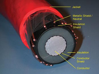
Shielding Of Power Cables
Shielding of an electric power cable is accomplished by surrounding the assembly or insulation with a grounded, conducting medium.
This confines the dielectric field to the inside of this shield.
Two distinct types of shields are used:
- Metallic
- Nonmetallic
.
.
The purposes of the insulation shield are to:
- Obtain symmetrical radial stress distribution withh the insulation.
- Eliminate tangential and longitudinal stresses on the surface of the insulation.
- Exclude from the dielectric field those materials such as braids, tapes, and fillers that are not intended as insulation.
- Protect the cables from induced or direct aver-voltages. Shields do this by making the surge impedance uniform along the length of the cable and by helping to attenuate surge potentials.
Conductor Shielding
In cables rated over 2,000 volts, a conductor shield is required by indusby standards. The purpose of the semiconducting, also called screening, material over the conductor is to provide a smooth cylinder rather than the relatively rough surface of a stranded conductor in order to reduce the stress concentration at the interface with the insulation. Conductor shielding has been used for cables with both laminar and extruded insulations. The materials used are either semiconducting materials or ones that have a high dielectric constant and are known as stress control materials. Both serve the same function of stress reduction.
Conductor shields for paper insulated cables are either carbon black tapes or metallized paper tapes. The conductor shieldmg materials were originally made of semiconducting tapes that were helically wrapped over the conductor. Present standards still permit such a tape over the conductor. This is done, especially on large conductors, in order to hold the strands together firmly during the application of the extruded semiconducting material that is now required for medium voltage cables. Experience with cables that only had a semiconductingtape was not satisfactory, so the industry changed their requirements to call for an extruded layer over the conductor.
In extruded cables, this layer is now extruded directly over the conductor and is bonded to the insulation layer that is applied over this stress relief layer. It is extremely important that there be no voids or extraneous material between those two layers.
Presentday extruded layers are not only clean (free from undesirable impurities) but are very smooth and round. This has greatly reduced the formation of water tress that could originate from irregular surfaces. By extruding the two layers at the same time, the conductor shield and the insulation are cured at the same time. This provides the inseparable bond that minimizes the chances of the formation of a void at the critical interface. For compatibility reasons, the extruded shielding layer is usually made from the same or a similar polymer as the insulation. Special carbon black is used to make the layer over the conductor semiconducting to provide the necessary conductivity. Industry standards require that the conductor semiconducting material have a maximum resistivity of 1,000 meter-ohms. Those standards also require that this material pass a long-time stability test for resistivity at the emergency operating temperature level to insure that the layer remains conductive and hence provides a long cable life.
A water-impervious material can be incorporated as part of the conductor shield to prevent radial moisture transmission. This layer consists of a thin layer of aluminum or lead sandwiched between semiconducting material. A similar laminate may be used for an insulation shield for the same reason.
There is no definitive standard that describes the class of extrudable shielding materials known as “super smooth, super clean”. It is not usually practical to use a manufacturer’strade name or product number to describeany material. The term “super smooth, super clean” is the only way at this writing to describe a class of material that provides a higher quality cable thanan earlier version. This is only an academic issue since the older type of materials are no longer used for medium voltage cable construction by known suppliers. The point is that these newer materials have tremendously improved cable performance in laboratory evaluations.
Insulation Shielding For Medium-Voltage Cables
The insulation shield for a medium voltage cable is made up of two components:
- Semiconducting or stress relief layer
- Metallic layer of tape or tap , drain wires, concentric neutral wires, or a metal tube.
They must function as a unit for a cable to achieve a long service life
Stress Relief Layer
The polymer layer used with exbuded cables has replaced the tapes shields that were used many years ago. This extruded layer is called the extruded insulation shield or screen. Its properties and compatibility requirements are similar to the conductor shield previously described except that standards require that the volume resistivity of thisexternal layer be limited to 500 meter-ohms.
The nonmetallic layer is directly Over the insulation and the voltage stress at that interface is lower than at the conductor shield interface.. This outer layer is not required to be bonded for cables rated up to 35 kV. At voltages above that, it is strongly recommendedt that this layer be bonded to the insulation .
Since most users want this layer to be easily removable, the Association of Edison Illuminating Companies (AEIC) has established strip tension limits. Presently these limits are that a 1/2 inch wide strip cut parallel to the conductor peel offwith a minimum of 6 pounds and a minimum of 24 pounds of force that is at a 90º angle to the insulation surface.
Metallic Shield
The metallic portion of the insulation shield or screen is necessary to provide a low resistance path for charging current to flow to ground. It is important to realize that the extruded shield materials will not survive a sustained current flow of more than a few milliamperes. These materials are capable of handing the small amounts of charging current, but cannot tolerate unbalanced or fault currents.
The metallic component of the insulation shield system must be able to accommodate these higher currents. On the other hand, an excessive amount of metal in the shield of a single-conductor cable is costly in two ways. First, additional metal over the amount that is actually required increases the initial cost of the cable. Secondly, the greater the metal component of the insulation shield, the higher the shield losses that result h m the flow of current in the central conductor.
A sufficient amount of metal must be provided in the cable design to ensure that the cable will activate the back-up protection in the event of any cable fault over the life of that cable. There is also the concern for shield losses.
It therefore becomes essential that:
- The type of circuitinterruptingequipmentto be analyzed.What is the design and operational setting of the hse, recloser, or circuit breaker?
- What fault current will the cable encounter over its life?
- What shield losses can be tolerated? How many times is the shield to be grounded? Will there be shield breaks to prevent circulating currents?
Concentric Neutral Cables
When concentric neutral cables are specified, the concentric neutrals must be manufactured in accordance with ICEA standards. These wires must meet ASTM B3 for uncoated wires or B33 for coated wires. These wires are applied directly over the nonmetallic insulation shield with a lay of not less than six or more than ten times the diameter over the concentric wires.
Shielding Of Low Voltage Cables
Shielding of low voltage cables is generally required where inductive interference can be a problem. In numerous communication, instrumentation, and control cable applications, small electrical signals may be transmitted on the cable conductor and amplified at the receiving end. Unwanted signals (noise) due to inductive interference can beaslargeasthedesiredsignal. This can result in false signals or audible noise that can effect voice communications.
Across the entire frequency spectrum, it is necessary to separate disturbances into electric field ef€ects and magnetic field effects.
Electric Fields
Electric field effects are those which are a function of the capacitive coupling or mutual capacitance between the circuits. Shielding can be effected by a continuous metal shield to isolate the disturbed circuit fiom the disturbing circuit. Even semiconducting extrusions or tapes supplemented by a grounded dmin wirecan serve some shielding function for electric field effects.
Magnetic Fields
Magnetic field effects are the result of a magnetic field coupling between circuits. This is a bit more complex thanfor electrical effects.
At relatively low frequencies, the energy emitted from the source is treated as radiation. This increases with the square of the frequency. This electromagnetic radiation can cause dislxrbancesat considerable distance and will penetrate any “openings” in the shielding. This can occur with braid shields or tapes that are not overlapped. The type of metal used in the shield also can effect the amount of disturbance. Any metallic shield material, as opposed to magnetic metals, will provide some shield due to the eddy currents that are set up in the metallic shield by the impinging field. These eddy currents tend to neutralize the disturbing field. Non-metallic, semiconducting shielding is not effective for magnetic effects. In general, the most effective shielding is a complete steel conduit, but thisis not always practical.
The effectiveness of a shield is called the “shielding factor” and is given as:
SF = Induced voltage in shield circuit / Inducted voltage in unshielded circuit
Test circuits to measwe the effectiveness of various shielding designs against electrical field effects and magnetic field effects have been reported by Gooding and Slade.
AUTHORS: Lawrence J. Kelly and Carl C. Landinger
.
Related articles
- Dry-Type disc wound transformers in MV applications
- Grounded or Ungrounded Systems
- Ispitivanje i održavanje energetskih transformatora
- UPS design criteria and selection
- Arc-resistant low voltage switchgear
5,185 views

Figure 1: Three generations of transformer substations
Early transformers were located at the top of pylons and could achieve powers of up to 1000kVA. Column-type transformer substations provided the interface between overhead and underground networks. These were equipped essentially with air-insulated MV switchgear, a liquid- insulated transformer and a low voltage distribution switchboard.
These were fabricated from bricks, and thanks to the chimney effect provided by the column the substations had good airflow, and consequently there were no problems with overheating of the equipment.
However the next generation of substations for underground networks also built from brick, had a reduced height and no chimney effect, and for the first time the equipment designers had to confront overheating problems.
This second generation of transformer substations was also the subject of the first internal fault tests, intended to provide operating personnel and the general public with greater levels of safety. The next step was the introduction of factory assembled prefabricated transformer substations.
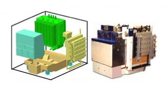
Figure 2: 630kVA qualified by EDF, validated against internal faults in the air and easily integrated into buildings.
This third generation of transformer substations were subject to the first international regulations. These substations were characterised by the use of more compact, environmentally insensitive equipment, factory assembled and standardised which means that Utilities can be supplied with series produced products, the production and performance of which are guaranteed by the tests carried out by the manufacturers in accredited laboratories.
For the third generation substations the first Utility specifications demanded small surface areas, leading to a standardised layout of the substations (Figure 1).
This enclosure can be metallic, GRC (Glass Reinforced Concrete), GRP (Glass Reinforced Plastic), SFRC (Steel Fibres Reinforced Concrete). The world wide trend is for reinforced concrete enclosures for the following reasons :
- Improved mechanical strength
- Reduced effect of solar radiation
- Reduced condensation
- Improved fire behaviour
- Weathering
- Improved aesthetic.
Finally, a fourth generation of transformer substations (Figure 2) has recently appeared, where the detailed technical specification has been replaced by functional specification.
AUTHORS: Thierry CORMENIER, ALSTOM-France; Robert DIDES.
.
Related articles
- Substation, Its Function And Types
- Superconducting transformers
- UPS design criteria and selection
- What is PowerLogic System?
- Current Switching with High Voltage Air Disconnector
2,931 views
Corona ions (air ionisation)
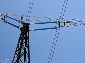
The intense electric field on the surface of powerline cables is sufficient to ionise the air, producing corona ions. This process is the cause of the characteristic buzzing or crackling of powerlines. Corona ions are routinely emitted from high voltage powerlines, especially in wet conditions. Corona ion effects have been measured up to 7 kilometres from powerlines both in the UK and in Germany. Corona ions are small electrically-charged particles which, when emitted from powerlines attach themselves to particles of air pollution, making these particles more likely to be trapped in the lung when inhaled. This phenomenon is sufficiently well recognised that pharmaceutical companies making inhalers are developing methods of charging up those aerosols to improve their effectiveness.
In this way people living near powerlines may be exposed to increased levels of air pollution. Crucially, corona ions can be carried several hundred metres from powerlines by the wind, so effects may be felt much further away than for magnetic fields. Fews and Henshaw, and colleagues at Bristol University (see refs) have estimated that corona ion effects, significant to adversely affect human health, extend to at least 400 metres from powerlines.
Bristol University found similar levels of corona ion pollution from 132kV lines as well as the much higher voltage lines studied in the Draper report (see refs). 132kV lines are much more common and straddle many houses and housing estates around the UK. Because of the quantity of research pointing towards serious health problems as a result of exposure to EMFs from power lines, etc., Powerwatch believes the Government should issue clear guidance to
- prevent any new building, especially homes, schools, nurseries, etc. within 250 metres of high-voltage powerlines
- enable the industry to start remedial work, such as undergrounding powerlines.
The regulator, OFGEM, should allow the industry to increase electricity prices slightly to fund this necessary work.
Although research has shown there is an increased risk of illness in high fields, most people, including most children, will not be seriously affected by them. It is important not to panic, but to take reasonable precautions.
.
Related articles
- Shielding Of Power Cables
- Reduction In The Cost Of Electricity
- Wind Power Applications
- Storage Systems
- Transformer Oil Diagnostics
2,739 views
The Power Factor Correction
The power factor of a load, which may be a single power-consuming item, or a number of items (for example an entire installation), is given by the ratio of P/S i.e. kW divided by kVA at any given moment.
The value of a power factor will range from 0 to 1. If currents and voltages are perfectly sinusoidal signals, power factor equals cos ϕ.
A power factor close to unity means that the reactive energy is small compared with the active energy, while a low value of power factor indicates the opposite condition.
Power vector diagram
- Active power P (in kW)
- Single phase (1 phase and neutral): P = V x I x cos ϕ
- Single phase (phase to phase): P = U x I x cos ϕ
- Three phase (3 wires or 3 wires + neutral): P = √3 x U x I x cos ϕ
- Reactive power Q (in kvar)
- Single phase (1 phase and neutral): P = V x I x sin ϕ
- Single phase (phase to phase): Q = UI sin ϕ
- Three phase (3 wires or 3 wires + neutral): P = √3 x U x I x sin ϕ
- Apparent power S (in kVA)
- Single phase (1 phase and neutral): S = VI
- Single phase (phase to phase): S = UI
- Three phase (3 wires or 3 wires + neutral): P = √3 x U x I
where:
V = Voltage between phase and neutral
U = Voltage between phases
- For balanced and near-balanced loads on 4-wire systems
The power factor is the ratio of kW to kVA. The closer the power factor approaches its maximum possible value of 1, the greater the benefit to consumer and supplier.
PF = P (kW) / S (kVA)
P = Active power
S = Apparent power
Current and voltage vectors, and derivation of the power diagram
The power vector diagram is a useful artifice, derived directly from the true rotating vector diagram of currents and voltage, as follows:
The power-system voltages are taken as the reference quantities, and one phase only is considered on the assumption of balanced 3-phase loading. The reference phase voltage (V) is co-incident with the horizontal axis, and the current (I) of that phase will, for practically all power-system loads, lag the voltage by an angle ϕ. The component of I which is in phase with V is the wattful component of I and is equal to I cos ϕ, while VI cos ϕ equals the active power (in kV) in the circuit, if V is expressed in kV.
The component of I which lags 90 degrees behind V is the wattless component of I and is equal to I sin ϕ, while VI sin ϕ equals the reactive power (in kvar) in the circuit, if V is expressed in kV.
If the vector I is multiplied by V, expressed in kV, then VI equals the apparent power (in kVA) for the circuit. The above kW, kvar and kVA values per phase, when multiplied by 3, can therefore conveniently represent the relationships of kVA, kW, kvar and power factor for a total 3-phase load, as shown in Figure K3 .
SOURCE: Schneider Electric
.
Related articles
- The Benefits of VFDs In HVAC Systems
- UPS design criteria and selection
- What is PowerLogic System?
- Substation, Its Function And Types
- General about motors
11,906 views
Field Test Procedure For Protective Relays
1. Relay Settings
At all new protective relay installations, the relays should be adjusted in accordance with the settings given in the relay data sheets, after which, tests should be made to determine if the actual operating characteristics check with the adjustments made. The Denver Office, Facilities Engineering Branch, must be advised of field changes of relay settings that become necessary from time to time as system operating conditions change to permit coordination with the Division of Design on future designs or revisions. Relays and relay settings are not to be changed from what is indicated on current issues of relay data sheets unless authorized by regional or project personnel with the proper responsibility.
.
2. Applying Revised Relay Settings
It is necessary to revise relay settings upward from time to time at many stations in preparation for anticipated increased unit output or line loading. At such times it may also be necessary to make corresponding changes in backup protective equipment in order to maintain coordination. Under these conditions, the changes in the backup relays should be made first so that coordination will not be lost during the period between beginning and completion of tests. This would apply whenever increased backup relay settings accompany changes in first-line protective equipment.
One case has been brought to our attention where new settings were applied to line relays but, because of lack of time, the backup ground relay was not reset until the following day. In the meantime, a fault occurred on the line, and the entire station was interrupted because the coordination had been lost. If the backup ground relay had been reset before settings were changed on line breaker relays, this interruption would not have occurred.
In a few rare cases relay settings may be revised downward at a station; and, in such cases, the opposite sequence must be followed in order to maintain coordination. When relay settings are revised downward, apply the new settings to the line breakers first and to the backup relays last.
.
3. New Installations
Before placing a new installation into operation, polarity of instrument transformers and the wiring to the relays should be checked. In some cases, the manufacturer’s polarity marking has been found to be incorrect. New relays should be inspected carefully and all blocking put in by the manufacturer removed. The test man should read instruction books furnished by the manufacturer to become familiar with construction and operating principle of the relays.
A sufficient number of initial operations should be made by manually operating relay contacts to make sure that all devices which should be operated by the relay, function freely and properly, including auxiliary contacts and targets within the relay. Breaker trip coils and other devices operated by the relay should be checked to see that proper operation is obtained at voltages considerably below normal (approximately 56 percent of normal voltage for breaker trip coils). The voltage drop in trip circuits and tripping current required should be checked. Factory adjustments on relays, other than taps, or other adjusting devices intended for customary adjustment should not be changed unless tests show that factory adjustments have been disturbed, in which case the manufacturers’ instruction books should be followed.
.
4. Testing Equipment Required
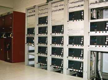
A good set of testing equipment and relay tools are important. Several manufacturers now produce portable relay test sets that will provided excellent results. If not available on the project, most of the equipment necessary can be borrowed from the Denver Office for making relay tests.
.
5. Testing Precautions
Before starting to test any relay on equipment in service, the person testing should become familiar with the relays and the circuits involved. Where test blocks are used, the person testing must make sure that in removing or inserting plugs that a current transformer circuit will not be opened, resulting in a voltage being built up which may be dangerous to personnel, property, or equipment, or cause an important circuit to trip out. In old installations where test blocks are not available, current transformer circuits must be short circuited by jumpers having reliable clamping devices which will not come loose, before the relay current circuit is opened.
.
6. Frequency Of Testing
It is recommended that protective and auxiliary relays be given a complete calibration test and inspection at least once a year. This schedule, however, sometimes cannot be met due to existing workloads and available manpower with the result that routine calibration tests intervals of many relays are longer than a year.
.
7. Test Records
A complete record should be kept of all test data and observations made during tests and inspections, including identifying numbers of test equipment used.
.
8. Annual Inspection
All relays shall be given an annual inspection. This inspection should include the following:
- A visual inspection should be made of all relays on a terminal including the tripping auxiliaries and accessories. Any drawout type relay should be withdrawn from its case for a closeup examination. All other, including auxiliaries, should at least have covers removed. Included in this visual inspection should be a check for loose connections, broken studs, burned insulation, and dirty contacts. Each relay should be checked to be in agreement with its setting sheet. On some distance relays it may have been necessary to set the taps on something other than specified values in order to get proper calibration. Because of this, it may also be necessary to check the taps against the last calibration test report.
- A test trip should be made of all relay systems. All relay elements which initiate some protective function should be checked. This includes reclosing, carrier starting, or any similar type function. After proving that tripping relays will successfully trip the circuit breaker and that all reclosing schemes work, continuity checks should be used, where applicable, to complete the checkout of the circuit breaker trip circuits.
.
9. Test Procedures
Tests to be performed during routine maintenance are determined by the type of relay to be tested. The following tests should be included for all electromechanical relays.
- A visual inspection of the relay cover can reveal valuable information. Any excessive dust, dirt, or. metallic material deposited on the cover should be noted and removed, thus preventing such material from entering the relay when the cover is removed. A cover glass which is fogged should be cleaned. Fogging is in most cases a normal condition due to volatile materials being driven out of coils and insulating materials, and is not an indication of a problem. However if fogging appears excessive, since most relays are designed to operate in ambient temperatures not exceeding 40EC (104EF), a further check of the ambient temperature would be in order. Voltage and current supplied to the relay should be checked and compared with the name plate or instruction book ratings. Should evidence of overheating be found, the insulation should be checked for embrittlement and, where necessary, replaced. Removal of the connection plug in drawout relays may reveal evidence of severe fault currents or contaminated atmospheres, either of which may indicate the advisability of a change in maintenance schedule. The condition of the relay contacts can be equally revealing.
- Mechanical adjustments and inspection should be made according to instructions shown following:
- Check to see that all connections are tight. Several loose connections could indicate excessive vibration which should be corrected.
- All gaps should be checked that they are freeof foreign material. If foreign material is found in the relay, the case gasket should be checked and replaced if necessary.
- All contact or armature gaps should bemeasured and values compared with previous measurements. Large variations in these measurements may indicate excessive wear, and worn parts should be replaced. Also an adjusting screw could have worked loose and must be tightened. All of this information should be noted on the test record.
- All contacts except those not recom-mended for maintenance should be burnished, and measured for alignment and wipe.
- Since checking bearings or pivotsusually involves dismantling the relay, it is recommended that such a test be made only when the relay appears to be extremely dirty, or when subsequent electrical tests indicate undue friction.
- Electrical tests and adjustments should be made according to the instructions shown following:
- Contact function.-Manually close oropen the contacts, and observe that they perform their required function; such as trip, reclose, or block.
- Pickup.-Gradually apply current or voltage to see that pickup is within limits. The current or voltage should be applied gradually in order to yield data which can be compared with previous or future tests and not be clouded by such effects as transient overreach.
- Dropout or reset.-To test for excessfriction, reduce current until the relay drops out or resets. Should the relay be sluggish in resetting or fail to reset, then the jewel bearing and pivot should be examined. A four power magnification is adequate for examining the pivot, and the jewel bearing can be examined with the aid of a needle which will reveal any cracks in it. If dirt is the problem, the jewel can be cleaned with an orange stick and the pivot can be wiped clean with a soft, lint free cloth. No lubricant should be used on either the jewel or pivot.
.
10. Auxiliary Relays
In addition to tests described in paragraph 9, auxiliary relays employing devices for time delay (for example, capacitors) should have an operating time test performed (either pickup or dropout, whichever is applicable).
.
11. Time Overcurrent And Time-Overvoltage Relays
All tests described in paragraph 9 should be performed for time-overcurrent and time-over-voltage relays where applicable. These types of relays should always be tested in the case in order to duplicate “in-service” conditions or to match published curves since the relay case normally acts as a shunt for flux that the electromagnetic iron circuit cannot handle due to saturation.
Testing the relay out of the case will also produce results that would not check previous tests or future tests since changes in test conditions, such as being near a steel cabinet, will change results obtained if the relay is tested out of the case. The first electrical test made on the relay should be a pickup test. Pickup is defined as that value of current or voltage which will just close the relay contacts from the
0.5 time-dial position. Allowing for such things asmeter differences and interpretations of readings, this value should be within ± 5 percent of previous data.
One or two points on the time-current curve are generally sufficient for maintenance purposes. Reset the relay to the original time-dial setting and check at two points such as 3 and 5 times pickup. Always use the same points for comparison with previous tests.
The instantaneous unit should be checked for pickup using gradually applied current. Whenever possible, current should be applied only to the instantaneous unit to avoid overheating the time unit. The target seal-in unit should also be tested using gradually applied current. The main unit contacts must be blocked closed for this test.
.
12. Directional Overcurrent Relays
In addition to tests recommended for the overcurrent relay, the directional unit of the directional overcurrent relay should be tested for minimum pickup, angle of maximum torque, contact gap, and clutch pressure. A test should also be made to check that the overcurrent unit operates only when the directional unit contacts are closed.
.
13. Distance Relays
When testing distance relays, tests should be made of pickup, angle of maximum torque, contact gap, and clutch pressure, in addition to the tests described in paragraph 9. (See appendix C for adjustment of Westinghouse Type KD relays).
.
14. Differential Relays
A test of minimum pickup should be performed for differential relays. The differential characteristic (slope) should be checked, and where applicable, the harmonic restraint should be tested. Differential relays using ultrasensitive polarized units as sensing devices are slightly affected by previous history, such as heavy internal or external fault currents. It is therefore recommended that for this type of relay two pickup readings be taken and the second reading be the one that is used for comparison with previous and future tests.
.
15. Static Relays
Static relays should be tested in accordance with manufacturer’s recommendations given in relay instruction books. As there are no moving parts in static relays, there is no physical wear due to usage and no need for lubricants. Prime causes of failure in electronic components are heat, vibration, and moisture. Overheating can be caused by voltage transients, current surges, excessive power, or high ambient temperature.
Vibration can loosen or break leads and connections and can crack component casings or insulation resulting in equipment failure. Moisture can result in corrosion of metallic elements which can result in circuit discontinuities, poor contact, or shorts. Preventive maintenance of static relays should be directed toward removing causes of failure listed above by doing the following:
- Keep equipment clean by periodic vacuuming or blowing out of dirt, dust, and other surface contaminants.
- Keep the equipment dry and protectedagainst moisture and corrosion.
- Inspect to see that all connections, leads,and contacts are tight and free as possible from effects of vibration.
- Check to see that there is adequateventilation to conduct heat away efficiently.
Preventive measures should not be applied unnecessarily as this may contribute to failures. For example, printed circuit cards should not be pulled from their racks to be inspected if there is no real need. Operating test switches unnecessarily may introduce damaging voltage transients.
.
16. Portable Relay Panels
Particular attention should be given to relays mounted on portable relay panels as these relays are subjected to more rough handling than those permanently installed on a switchboard. Therefore, whenever a portable panel of relays is installed, they should be thoroughly checked physically as well as electrically. If they are in bad condition, they should be repaired, or new relays installed before they are placed in service.
.
17. Circuit Burden Measurements For CT’S
When CT circuits are modified such as by addition of relays, meters, or auxiliary CT’s, measurements should be taken to determine the burden of the overall CT secondary circuit. These measurements should normally be on a phase-to-neutral basis. Measurements should be made at three current levels, such as 1, 3, and 5, while recording volts, amps, and phase angle. When auxiliary CT’s are involved, additional and separate measurements should be taken on the secondary circuit of the auxiliary CT’s.
.
18. Excitation Curves For CT’S
Auxiliary CT’s tend to saturate at much less secondary current and burden than large multi-ratio bushing type CT’s. Excitation curves should be available on all CT’s, especially on auxiliary CT’s used in protective relaying circuits (fig. 1). Such curves can be derived by open-circuiting the primary, and driving the secondary with a 60-Hertz source while measuring voltage and current. Readings should be taken up to two times rated secondary current or to the point where voltage applied is 1500 volts.
.
19. Grounding CT And PT Circuits
The CT and PT circuits should be grounded at only one point. Relay misoperations can be caused by grounding the neutral at two points, such as one ground at the switchyard and another at the relay panel. At least once every 3 years with the primary deenergized, the known ground should be removed and the overall circuits should be checked for additional grounds and insulation breakdowns.
.
20. Open-Secondary Circuits
WARNING: Secondary circuits of CT’s must not be open while primary current flows.
Extreme care should be taken to avoid breaking the secondary circuit while primary current is flowing. If the secondary is open-circuited the primary current raises core flux density to saturation and induces a high voltage in the secondary which can endanger human life, and can damage connected apparatus and leads. If it is necessary to change secondary conditions while primary current is flowing, the secondary terminals must be short-circuited while the change is being made. Caution should be exercised when working with differential circuits as shorting a current transformer in an energized differential relaying circuit could result in a relay operation.
It is recommended that the secondaries of all current transformers be kept short-circuited at all times when not installed in a circuit such as being held in stock or being transported.
.
21. Tempererature Relays
Temperature relays used on bearings and for other important purposes should be checked for correct operation by placing the bulb in a pail of water with a thermometer, and gradually heating to the temperature at which the relay is set to operate. A mercury or alcohol thermometer should be used to read the temperature while the water is being stirred.
Record temperature at which the relay operates on increasing temperature and at which it resets on falling temperature. Temperature relays operating from RTD’s (resistance temperature detectors) should be checked by heating the detectors slowly in an enclosed air space since they should not be immersed in water or other liquid.
.
22. Pressure Relays
Pressure relays should be checked for correct operation by comparing with an accurate pressure gage. Pressure should be increased and decreased to determine the pressure at which the relay operates and resets. The above does not apply to sudden pressure relays, which should be maintained in accordance with the manufacturer’s recommendations.
.
Related articles
- Line Protection With Distance Relays
- ABB Power Transformers – A guide to manufacturing
- High Voltage Substation Earth Grid Impedance Testing
- ABB Feeder Protection REF615 ANSI
- Procedure for the establishment of a new substation
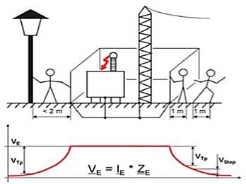
FIGURE 1 – Voltage gradient around a substation under fault condition
The purpose of this paper is to report a new test method and make a recommendation to improve the procedures according to the findings.
The test method involves measurement of high voltage substations earth grid impedance, by utilization of a variable frequency current source and frequency selective measurement techniques.
Safety policies require that the values of earth impedances remain within the specified acceptable range and every utility is required to guarantee safe step-and-touch potential levels. It is therefore necessary to carry out periodic testing on substation earthing to monitor the condition of the substation earthing system.
Knowledge of earth grid impedance of high voltage substations is also very important for correct operation of protection schemes and fault clearance. As the condition of grounding components change over time due to corrosion of earth cables, changes in the adjacent infrastructures and so on, it is necessary to measure the impedance of earthing grid periodically to ensure that the values are within expected range.
Knowledge of the overall resistance ZE allows calculation of the total voltage rise of a substation under maximum fault current. Knowledge of the voltage gradient around the substation, especially close to the substation allows calculation of the step-andtouch voltages under worst-case conditions.
Measurement principle
According to international standards such as CENELEC HD637S1 [1] or ANSI IEEE 80-2000 [2], 81-1983 [3] it is recommended to use a current-voltage method otherwise known as fall-of-potential [4].
Generally in a 90° angle (birds-eye view) two electrodes are placed outside the influence of the grounding system under test. One is used to inject the current (current electrode) and one to measure the voltage (voltage electrode). However because the area which is influenced by the grounding system is not so easy to determine, the current electrode is usually placed at a distance of at least 10 times, and up to 15 to 20 times the diameter of the grounding system under test. The voltage electrode then is placed in various distances.
Close to the system under test, large voltage degradation is visible. The further the voltage probe is located from the system under test, the more stable the measured voltages become (FIGURE 2 & 6).

FIGURE 2 – Voltage Degradation
Problems with Conventional Measurement Methods
For small grounding systems like a single tower, it is generally no problem to place the two needed electrodes and low currents generated by battery-operated equipment can generally do the job satisfactorily. However when measuring large substations, the distances are substantial and should be as large as 10 to 20 times the diameter of the substation. In some cases, measurements show peaks and drops until an area free of buildings and buried conductors or pipes is reached. Until then, erroneous results can be obtained.
Voltage drops can be observed when measurement points are set close to objects, like towers of power lines leaving the substation, connected to the grounding system under test. Voltage rises can be observed when for example measurement points are placed over a buried pipe that runs close to the current electrode. Therefore it is often difficult to distinguish between drops, rises and stable results.
To place the current electrode very far away is certainly a good idea, because then at least the influence of the current electrode can be minimized, however here the effort becomes even bigger. The biggest challenge is when the current electrode has to be relocated several times, before a stable measurement can be achieved.
Usage of existing power lines
One method to overcome these measurement problems is to use diesel generators (weighing several tons) to generate currents that have frequencies slightly different from mains frequency and to feed in the currents over existing, de-energized power lines leaving the substation. The grounding system of the remote substation where the power line terminates is used as current electrode (see FIGURE 2 Impedance Measurement).
The amount of current needed for such a test still has to be quite large to overcome mains frequency disturbances and the power requirement is enormous. But with these devices it is possible to measure ground impedances. However, the effort is by far too high to use it as a realistic approach for maintenance measurements.
Combination of the good ideas

FIGURE 3 – Test equipment for line impedance measurement
A new approach of Omicron is to combine the principle of simple battery operated equipment based on the variable frequency principle and use the existing power lines and the grounding system of the remote substation as current electrode.
The test set CPC 100 and CP CU1 from OMICRON comprises of a frequency variable amplifier (29 kg), a coupling unit (28 kg) and a protection device (6 kg).
The CPC 100 is a multi-functional, frequency-variable test set for testing various primary equipments. It is capable of generating currents up to 800 A or voltages up to 2000 V, with special software modules to be used for various automated tests on CTs, VTs, power transformers or other primary equipments. With other accessories it can also be used for tangent delta testing on power transformer bushings or windings, with test voltages up to 12 kV.
In the application of ground impedance measurement it is used as frequency variable power generator, measurement tool and analyzer. Due to the variable frequency generation, it is possible to generate signals first under and then above mains frequency. Using digital filter algorithms, the test set will measure only the signal with the frequency that is currently generated and filters out signals at other frequencies. Disturbances due to noise and electrical interference thus no longer influence the result.
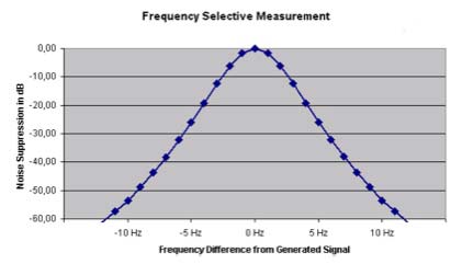
FIGURE 4 – Frequency selective measurement
For safety reasons, the coupling unit CP CU1 is used for galvanic decoupling of the current output and the measurement inputs from the power line. This way, if fault or lightning occur during the test, the operator can be safe from dangerous voltages. For optimum performance there is a range selector switch for the current output, and a built-in voltmeter for a quick check of induced voltages or burden. Test currents of up to 100A can be generated for short cables, and for long lines of up to a few hundred kilometers, currents over 1A are still possible.
The protection device CP GB1 is a tool for easy connection to the overhead line or power cable and existing grounding cables of the substation may be used. In case of unexpected high voltage on the power line due to faults on a parallel system, lightning discharges or transients due to switching operations, the GB1 is capable of discharging short transients or permanently shorting fault currents of up to 30 kA for at least 100 ms. These features will protect the operator in unexpected situations.
The test itself is simple: the combination of CPC 100, CP CU1 and CP GB1 is connected to a de-energized power line (FIGURE 2&5); after removing the near end ground connection, test current with a different frequency than the mains frequency is injected. The voltage test probe then is located at various distances until stable voltage measurements can be observed. At this point the measurement is completed And the results can be stored in the CPC, downloaded to a PC and analyzed in a Microsoft Excel application.
Case study
The test was carried out on 7th October 2004 by confirming outage on Western Power Corporation’s Landsdale Northern Terminal line. Northern Terminal Substation was the remote terminal and the earth grid at Landsdale Substation was measured.
Earth Switches at both substations were closed and portable earths were applied to the lines in preparation for the test.
CPC 100 and CP CU20 (a predecessor of the CP CU1) were connected to the line as per test set up and voltage measurements stake was inserted at different distances from the test point in a different direction from that of the transmission line in order to avoid induction. Measurements were carried out and test files were saved to the CPC 100 memory to be retrieved in the office.
Test was performed at various frequencies (between 30-110 Hz) to suppress the noise and achieve a precise characteristic of the grid impedance under test. Impedances for 50Hz were extrapolated from the test results.
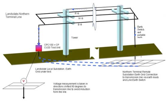
FIGURE 5 – Measurement of Landsdale Local Substation's Earth Grid
The mass of the earth is not the only path for feeding the ground current. All metal structures such as pipes tubes, railway lines and Multiple Earthed Neutral (MEN) of distribution systems between the test point and the current auxiliary electrode form the path for the ground current, including the shield wire on the top of the pole.
Test Results
The graph for the impedance measurement was as follows:
FIGURE 6 – Voltage degradation measurement results
The impedance profile of the earthing system was obtained and the stabilization of the impedance at a distance above 100m was obvious.
This data was then used to calculate the earthgrid potential rise during maximum earth fault conditions.
Conclusion
Substation earthing system testing using the conventional method is arduous, time consuming and involves multiple heavy equipment producing end results that are sometimes unreliable due to electrical interference and noise. The conventional method requires high test currents in order to achieve a higher signal-to-noise ratio, therefore heavy equipment and generators are required to produce such currents.
The alternative method using variable frequency technique, achieves the desired outcome with less cost, effort and resources and increases efficiency and accuracy.
AUTHORS
Dean SHARAFI – WESTERN POWER (Australia)
Ulrich KLAPPER – OMICRON electronics (Australia)
.
Related articles
- ABB launches new generation 420kV gas insulated switchgear
- ABB Power Transformers – A guide to manufacturing
- Line Protection With Distance Relays
- Substation, Its Function And Types
- Current Switching with High Voltage Air Disconnector
21,241 views
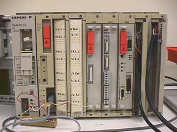
PLC-Based Monitoring Control System
With the rapidly changes on industries and information technologies in recent years, some traditional bulk electronic appliances have to be monitored for a long time. All of their control devices such as communication interfaces gradually enter the Intemet information era. The control of all equipment has been performed through the use of computers.
Most equipment uses PLC to connect with computers to monitor each load and electricity consuming devices. Programmable Logic Controllers (PLC) are widely used in industrial control because they are inexpensive, easy to install and very flexible in applications. A PLC interacts with the external world through its inputs and outputs.
PLC as a System Controller
Programmable logic controllers are modular, industrially hardened computers which perform control functions through modular input and output (I/O) modules. The modularity of PLC allows the user to combine generic I/O modules with a suitable controller to form a control system specific to his is most simply understood needs. The operation of a controller by envisioning that it repeatedly performs three steps:
- Reads inputs from input modules
- Solves preprogrammed control logic
- Generates outputs to output modules based on the control logic solutions. Input devices and output devices of the process are connected to the PLC and the control program is entered into the PLC memory (Fig.1).

Fig. 1. Control Action of a PLC
In our application, it controls through analog and digital inputs and outputs the varying load-constant speed operation of an induction motor.
Also, the PLC continuously monitors the inputs and activates the outputs according to the control program. This PLC system is of modular type composed of specific hardware building blocks (modules), which plug directly into a proprietary bus: a central processor unit (CPU), a power supply unit, input-output modules I/O and a program terminal.
Such a modular approach has the advantage that the initial configuration can be expanded for other future applications such as multi machine systems or computer linking [2].
Control System of Induction Motor
The software models generated in the Software Requirements Analysis phase of the development project are refined and embellished in the design phase of the project. This phase involves making implementation decisions such as the interfacing between different software modules, the break down of software across multiple processors, assigning inputs and outputs to I/O cards, etc. PLC software, once written must be easy and intuitive to follow.
PLCs are an integrated part of the domain system, advances in the technology of the system will effect the requirements of the PLC software. PLC software must therefore be maintainable and extensible [18].

Fig. 2. Experimental setup
In Fig. 2, the block diagram of the experimental system is illustrated. The following configurations can be obtained from this setup.
- A closed-loop control system for constant speed operation, configured with speed feedback. The induction motor drives a variable load, is fed by an inverter and the PLC controls the inverter output.
- An open-loop control system for variable speed and variable frequency operation. The induction motor drives a variable load and is fed by control mode. The PLC is an inverter in constant in activated.
- The standard variable speed operation. The induction motor drives a variable load and is fed by a constant voltage-constant frequency standard three-phase supply.
The open-loop configuration (2.) can be obtained from the closed-loop configuration (1.) by removing the speed feedback. On the other hand, operation c) results if the entire control system is bypassed. [6-7] PLC’s programming is based on the logic demands of input devices and the programs implemented are predominantly logical rather than numerical computational algorithms. Most of the programmed operations work on a straightforward two-state “on or off” basis and these alternate possibilities correspond to “true or false” (logical form) and“ 1 or 0” (binary form), respectively. Thus, PLCs offer a flexible programmable alternative to electrical circuit relay-based control systems built using analog devices.
The programming method used is the ladder diagram method. The PLC system provides a design environment in the form of software tools running on a host computer terminal which allows ladder diagrams to be developed, verified, tested, and diagnosed. First, the high-level program is written in ladder diagrams. Then, the ladder diagram is converted into binary instruction codes so that they can be stored in random-access memory (RAM) or erasable programmable read-only memory (EPROM). Each successive instruction is decoded and executed by the CPU. The function of the CPU is to control the operation of memory and I/O devices and to process data according to the program. Each input and output connection point on a PLC has an address used to identify the I/O bit. The method for the direct representation of data associated with the inputs, outputs, and memory is based on the fact that the PLC memory is organized into three regions: input image memory (I), output image memory (Q), and internal memory (M).
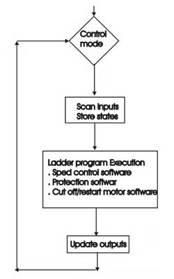
Fig.3. Flowchart of the main program
Any memory location is referenced directly using %I, %Q, and %M (Table III). The PLC program uses a cyclic scan in the main program loop such that periodic checks are made to the input variables (Fig.3). The program loop starts by scanning the inputs to the system and storing their states in fixed memory locations (input image memory I).
The ladder program is then executed rung-by-rung. Scanning the program and solving the logic of the various ladder rungs determine the output states. The updated output states are stored in fixed memory locations (output image memory Q). The output values held in memory are then used to set and reset the physical outputs of the PLC simultaneously at the end of the program scan. For the given PLC, the time taken to complete one cycle or the scan time is 0, 18 ms/K (for 1000 steps) and with a maximum program capacity of 1000 steps.
The development system comprises a host computer (PC) connected via an RS232 port to the target PLC. The host computer provides the software environment to perform file editing, storage, printing, and program operation monitoring.
The process of developing the program to run on the PLC consists of: using an editor to draw the source ladder program, converting the source program to binary object code which will run on the PLC’ s microprocessor and downloading the object code from the PC to the PLC system via the serial communication port.
The PLC system is online when it is in active control of the machine and monitors any data to check for correct operation.

Table 1. Induction Motor Technical Specifications
.

Table 2. Inverter Technical Specifications
.
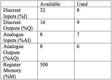
Table 3. PLC Configuration
.
As a microprocessor-based system, the PLC system hardware is designed and built up with the following modules [7]:
- Central processor unit (CPU)
- Discrete output module (DOM)
- Discrete input module (DIM)
- Analog outputs module (AOM)
- Analog inputs module (AIM)
- Power supply
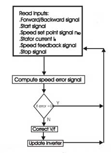
Fig. 4. Flowchart of speed control software
In Fig.4, the flowchart of the speed control software is illustrated. The software regulates the speed and monitors the constant speed control regardless of torque variation. The inverter being the power supply for the motor executes this while, at the same time, it is controlled by PLC’ s software. The inverter alone can not keep the speed constant without the control loop with feedback and PLC. From the control panel, the operator selects the speed set point nsp and forward/backward direction of rotation. Then, by pushing the manual start pushbutton, the motor begins the rotation. If the stop button is pushed, then the rotation stops.
The corresponding input signals are interfaced to the DIM and the output signals to the DOM. The AIM receives the trip signal from the stator current sensor, the speed feedback signal from the tacho-generator, and the signal from the control panel. In this way, the PLC reads the requested speed and the actual speed of the motor. The difference between the requested speed by the operator and the actual speed of the motor gives the error signal. If the error signal is not zero, but positive or negative, then the PLC according to the computations carried out by the CPU decreases or increases the V/f of the inverter and, as a result, the speed of the motor is corrected.
The implemented control is of proportional and integral (PI) type (i.e., the error signal is multiplied by gain Kp, integrated and added to the requested speed). As a result, the control signal is sent to the DOM and connected to the digital input of the inverter to control V/f variations. At the beginning, the operator selects the gain Kp, by using a rotary resistor mounted on the control panel (gain adjust) and the AIM receives its voltage drop as controller gain signal (0–10 V). The requested speed nsp is selected using a rotary resistor and the AIM reads this signal. Its value is sent to the AOM and displayed at the control panel (speed set point display).
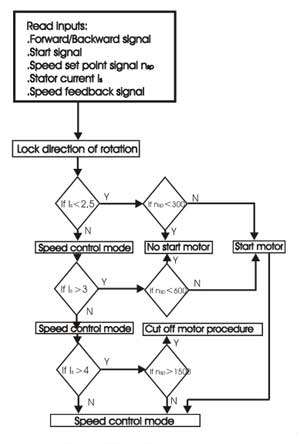
Fig. 5. Flowchart of monitor and protection Software
Another display of the control panel shows the actual speed computed from the speed feedback signal. In Fig. 5, the flowchart of this software is shown.
During motor operation, it is not possible to reverse its direction of rotation by changing the switch position. Before direction reversal, the stop button must be pushed. For motor protection against overloading currents during starting and loading, the following commands were programmed into the software.
1. Forward/backward signal is input to DIM
2. Speed set point signal nsp, the stator current IS and the speed feedback signal are input to AIM.
3. At no load, Is ≤ 2,5 A, if the speed set point is lower than 20% or nsp< 300 r/min, the motor will not start.
4. At an increased load over 3,2 Nm (40% of rated torque), Is ≥ ,3 A and a speed set point lower than 40% or nsp< 600 r/min, the motor will not start.
5. If the load is increased more than 8,0Nm (rated torque) Is ≥ 4 A and if the speed set point exceeds 100% or nsp≥ 1500 r/min, the motor enters the cut off procedure.
6. In all other situations, the motor enters in the speed control mode and the speed control software is executed as described in Subsection A.
In Fig. 6, the flowchart of this software is shown.
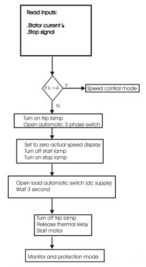
Fig. 6. Flowchart of cutoff/restart motor software
- In overloading situations, the motor is cut off and the trip lamp (yellow) is lit. The operator must release the thermal relays and then must turn off the trip lamp by pushing trip or stop button. The thermal relays are set to the motor rated current 4 A. Following this, the motor can be started again.
- The motor can be cut off by the operator pushing the stop button: the display of the actual speed is set to zero, the start lamp (green) turns off, and the stop lamp (red) turns on and remains lit for 3 s.
- The load must be disconnected immediately after the motor cuts off and before the drive system is restarted. The motor will not start before 3 s after cutoff even if the start button is pushed.
Results
The system was tested during operation with varying loads including tests on induction motor speed control performance and tests for trip situations. The PLC monitors the motor operation and correlates the parameters according to the software. At the beginning, for reference purposes, the performance of induction motor supplied from a standard 380V, 50-Hz network was measured. Then, the experimental control system was operated between no load and full load (8, 0 Nm) in the two different modes described above:
- Induction motor fed by the inverter and with PLC control
- Induction motor fed by the inverter
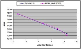
Fig. 7. Experimental speed torque characteristics with PLC and inverter
The range of load torque and of speed corresponds to the design of the PLC hardware and software as described in the previous sections. The speed versus torque characteristics were studied in the range 500–1500 r/min and are illustrated in Fig. 7. The results show that configuration b) operates with varying speedvarying load torque characteristics for different speed set points nsp.
Configuration (1.) operates with constantspeed-varying load torque characteristics in the speed range 0–1400 r/min and 0–100% loads. However, in the range of speeds higher than 1400 r/min and loads higher than 70%, the system operates with varying-speedvarying-load and the constant speed was not possible to be kept. Thus, for nsp ≥ 1400 r/min both con-figurations (1.) and (2.) have a similar torque-speed response. This fact shows that PI control for constant speed as implemented by the software with PLC is effective at speeds lower than 93% of the synchronous[4-7].
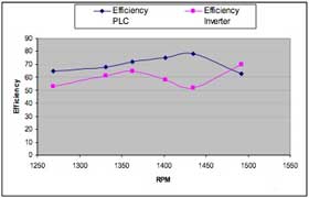
Fig. 8. Efficiency of controlled system
The efficiency for different values of nsp was also studied. As depicted in Fig. 8, the results show that configuration (1.) in all cases has a higher efficiency than configuration (2.). Also, at operation with loads higher than 70%, the normalized efficiency is η(pu)> 1, meaning that the obtained efficiency with PLC control is higher than the efficiency of induction motor operated from the standard 380-V, 50-Hz network without the control of PLC and without the inverter.
According to this figure, the efficiency of PLC-controlled system is increased up to 10–12% compared to the standard motor operation. From a theoretical point of view, if we neglect magnetizing current, an approximate value for the efficiency is

where is the slip and Rs and Rr are the stator and rotor winding resistances, respectively. As can be seen from Fig. 7, the PLC controlled system a) works with very low slip values, almost zero. In all speed and load torque conditions, the configuration (1.) has a smaller slip than configuration (2.), thus the higher values of efficiency can be justified and especially at high speeds and frequencies. At lower frequencies, the magnetic flux increases and, thus, there is an increase in magnetizing current resulting in increased losses. This system presents a similar dynamic response as the closed-loop system with V/f speed control. Its transient performance is limited due to oscillations on torque and this behavior restricts the application of this system to processes that only require slow speed variation.
Conclusion
Successful experimental results were obtained from the previously described scheme indicating that the PLC can be used in automated systems with an induction motor.
The monitoring control system of the induction motor driven by inverter and controlled by PLC proves its high accuracy in speed regulation at constant-speedvariable-load operation. The effectiveness of the PLC-based control software is satisfactory up to 96% of the synchronous speed. The obtained efficiency by using PLC control is increased as compared to the open-loop configuration of the induction motor fed by an inverter. Specifically, at high speeds and loads, the efficiency of PLC-controlled system is increased up to 10–12% as compared to the configuration of the induction motor supplied from a standard network.
Despite the simplicity of the speed control method used, this system presents:
- constant speed for changes in load torque
- full torque available over a wider speed range
- very good accuracy in closed-loop speed control scheme
- higher efficiency;
- overload protection
Thus, the PLC proved to be a versatile and efficient control tool in industrial electric drives applications.
AUTHORS:
YASAR BIRBIR, H.SELCUK NOGAY
Marmara University, Technical Education Faculty, Department of Electricity Education
Goztepe, 34722 Istanbul, TURKEY.
ybirbir@marmara.edu.tr, selcuknogay@marmara.edu.tr
.
Related articles
- Video Surveillance in Power Substations
- Energy management
- What is PowerLogic System?
- General about motors
- Paralleling Three-Phase Transformers
8,774 views
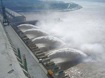
Gezhou HidroPower Dam
Hydropower (from hydro meaning water) is energy that comes from the force of moving water. The fall and movement of water is part of a continuous natural cycle called the water cycle. Energy from the sun evaporates water in the earth’s oceans and rivers and draws it upward as water vapor.
When the water vapor reaches the cooler air in the atmosphere, it condenses and forms clouds. The moisture eventually falls to the earth as rain or snow, replenishing the water in the oceans and rivers. Gravity drives the water, moving it from high ground to low ground. The force of moving water can be extremely powerful.
Hydropower is called a renewable energy source because the water on the earth is continuously replenished by precipitation. As long as the water cycle continues, we won’t run out of this energy source.
History of Hydropower
Hydropower has been used for centuries. The Greeks used water wheels to grind wheat into flour more than 2,000 years ago. In the early 1800s, American and European factories used the water wheel to power machines. The water wheel is a simple machine. The water wheel is located below a source of flowing water.
It captures the water in buckets attached to the wheel and the weight of the water causes the wheel to turn. Water wheels convert the potential energy (gravitational energy) of the water into motion. That energy can then be used to grind grain, drive sawmills, or pump water.
In the late 19th century, the force of falling water was used to generate electricity. The first hydroelectric power plant was built at Niagara Falls in 1879. In the following decades, many more hydroelectric plants were built. At its height in the early 1940s, hydropower provided 33 percent of this country’s electricity.
By the late 1940s, the best sites for big dams had been developed. Inexpensive fossil fuel plants also entered the picture. At that time, plants burning coal or oil could make electricity more cheaply than hydro plants. Soon they began to underprice the smaller hydroelectric plants. It wasn’t until the oil shocks of the 1970s that people showed a renewed interest in hydropower.
Hydro Dams
It’s easier to build a hydro plant where there is a natural waterfall. That’s why the first hydro plant was built at Niagara Falls. Dams, which are artificial waterfalls, are the next best way.
Dams are built on rivers where the terrain will produce an artificial lake or reservoir above the dam. Today there are about 80,000 dams in the United States, but only three percent (2,000) have power-generating hydro plants. Most dams are built for flood control and irrigation, not electric power generation. A dam serves two purposes at a hydro plant. First, a dam increases the head or height of the water. Second, it controls the flow of water. Dams release water when it is needed for electricity production. Special gates called spillway gates release excess water from the reservoir during heavy rainfalls.
Hydropower Plants

Hydropower Plant Parts
As people discovered centuries ago, the flow of water represents a huge supply of kinetic energy that can be put to work. Water wheels are useful for generating mechanical energy to grind grain or saw wood, but they are not practical for generating electricity. Water wheels are too bulky and slow.
Hydroelectric plants are different. They use modern turbine generators to produce electricity, just as thermal (coal, oil, nuclear) power plants do, except that they do not produce heat to spin the turbines.
How a Hydro Plant Works
A typical hydro plant is a system with three parts:
- a power plant where the electricity is produced.
- a dam that can be opened or closed to control water flow
- a reservoir (artificial lake) where water can be stored
To generate electricity, a dam opens its gates to allow water from the reservoir above to flow down through large tubes called penstocks. At the bottom of the penstocks, the fast-moving water spins the blades of turbines. The turbines are connected to generators to produce electricity. The electricity is then transported via huge transmission lines to a local utility company.
Head and Flow
The amount of electricity that can be generated at a hydro plant is determined by two factors: head and flow. Head is how far the water drops. It is the distance from the highest level of the dammed water to the point where it goes through the power-producing turbine.
Flow is how much water moves through the system––the more water that moves through a system, the higher the flow. Generally, a high-head plant needs less water flow than a low-head plant to produce the same amount of electricity.
Storing Energy
One of the biggest advantages of a hydropower plant is its ability to store energy. The water in a reservoir is, after all, stored energy. Water can be stored in a reservoir and released when needed for electricity production.
During the day when people use more electricity, water can flow through a plant to generate electricity. Then, during the night when people use less electricity, water can be held back in the reservoir. Storage also makes it possible to save water from winter rains for summer generating power, or to save water from wet years for generating electricity during dry years.
Pumped Storage Systems
Some hydro plants use pumped storage systems. A pumped storage system operates much as a public fountain does. The same water is used again and again. At a pumped storage hydro plant, flowing water is used to make electricity and then stored in a lower pool. Depending on how much electricity is needed, the water may be pumped back to an upper pool. Pumping water to the upper pool requires electricity so hydro plants usually use pumped storage systems only when there is peak demand for electricity.
Pumped hydro is the most reliable energy storage system used by American electric utilities. Coal and nuclear power plants have no energy storage systems. They must turn to gas and oil-fired generators when people demand lots of electricity. They also have no way to store any extra energy they might produce during normal generating periods.
Hydropower Production
How much electricity do we get from hydropower today? Depending on the amount of rainfall, hydro plants produce from five to ten percent of the electricity produced in this country (10 percent in 1997, 5.9 percent in 2008 due to the droughts in the west. In Oregon, Washington, and Idaho, hydropower supplies over 73 percent of the electricity each year. Today, there are about 78 million kilowatts of hydro generating capacity in the United States. That’s equivalent to the generating capacity of 80 large nuclear power plants. The biggest hydro plant in the U.S. is located at the Grand Coulee Dam on the Columbia River in northern Washington State. The United States also gets some hydropower generated electricity from Canada.
Some New England utilities buy this imported electricity. What does the future look like for hydropower? The most economical sites for hydropower dams have already been developed so the development of big hydro plants is unlikely. Existing plants could be enlarged to provide additional generating capacity. Plus, many flood-control dams not equipped for electricity production could be retrofitted with generating equipment. The Federal Energy Regulatory Commission estimates 30 thousand megawatts of additional generating capacity could be developed in the United States.
Hydropower for Baseload Power
Demand for electricity is not steady; it goes up and down. People use more electricity during the day when they are awake and using electrical appliances, and less at night when they are asleep.
People also use more electricity when the weather is very cold or very hot. Electric utility companies have to produce electricity to meet these changing demands. Baseload power is the electricity that utilities have to generate all the time. For that reason, baseload power should be cheap and reliable. Hydropower meets both these requirements.
Generating electricity with hydropower is the cheapest way to generate electricity in the U.S., and the fuel supply flowing water is always available. Hydro plants are more energy efficient than most thermal power plants, too. That means they waste less energy to produce electricity. In thermal power plants, a lot of energy is lost as heat. Hydro plants are about 95 percent efficient at converting the kinetic energy of the moving water into electricity.
Economics of Hydropower
Hydropower is the cheapest way to generate electricity today. No other energy source, renewable or nonrenewable, can match it.
Today, it costs about one cent per kWh (kilowatt-hour) to produce electricity at a typical hydro plant. In comparison, it costs coal plants about three cents per kWh and nuclear plants about two cents per kWh to generate electricity. Producing electricity from hydropower is cheap because, once a dam has been built and the equipment installed, the energy source—flowing water—is free.
Hydropower plants also produce power cheaply due to their sturdy structures and simple equipment. Hydro plants are
dependable and long-lived, and their maintenance costs are low compared to coal or nuclear plants. One requirement may increase hydropower’s costs in the future. The procedure for licensing and relicensing dams has become a lengthy
and expensive process. Many environmental impact studies must be undertaken and as many as 13 state and federal agencies must be consulted. It takes anywhere from three to seven years to get a license to build a hydroelectric dam or a relicense to continue operations.
Hydropower and the Environment

Hydropower can potentially harm fish
Hydropower dams can cause several environmental problems, even though they burn no fuel. Damming rivers may permanently alter river systems and wildlife habitats.
Fish, for one, may no longer be able to swim upstream. Hydro plant operations may also affect water quality by churning up dissolved metals that may have been deposited by industry long ago. Hydropower operations may increase silting, change water temperatures, and lower the levels of dissolved oxygen.
Some of these problems can be managed by constructing fish ladders, dredging the silt, and carefully regulating plant
operations. Hydropower has advantages, too. Hydropower’s fuel supply (flowing water) is clean and is renewed yearly by snow and rainfall. Furthermore, hydro plants do not emit pollutants into the air because they burn no fuel. With growing concern over greenhouse gas emissions and increased demand for electricity, hydropower may become more important in the future.
Hydropower facilities offer a range of additional benefits. Many dams are used to control flooding and regulate water supply, and reservoirs provide lakes for recreational purposes, such as boating and fishing.
.
Related articles
- Hydropower – Systems Overview (1)
- Introduction To Micro Hydropower
- Hydropower – Systems Overview (2)
- The Nature Of Reactive Energy
- Storage Systems
2,781 views
One of the significant challenges that substation engineers face is justifying substation automation investments. The positive impacts that automation has on operating costs, increased power quality, and reduced outage response are well known. But little attention is paid to how the use of a communication standard impacts the cost to build and operate the substation. Legacy communication protocols were typically developed with the dual objective of providing the necessary functions required by electric power systems while minimizing the number of bytes that were used by the protocol because of severe bandwidth limitations that were typical of the serial link technology available 10-15 years ago when many of these protocols were initially developed. Later, as Ethernet and modern networking protocols like TCP/IP became widespread, these legacy protocols were adapted to run over TCP/IP-Ethernet.
This approach provided the same basic electric power system capabilities as the serial link version while bringing the advantages of modern networking technologies to the substation. But this approach has a fundamental flaw: the protocols being used were still designed to minimize the bytes on the wire and do not take advantage of the vast increase in bandwidth that modern networking technologies deliver by providing a higher level of functionality that can significantly reduce the implementation and operational costs of substation automation.
IEC 61850 is unique. IEC 61850 is not a former serial link protocol recast onto TCP/IP-Ethernet. IEC 61850 was designed from the ground up to operate over modern networking technologies and delivers an unprecedented amount of functionality that is simply not available from legacy communications protocols. These unique characteristics of IEC 61850 have a direct and positive impact on the cost to design, build, install, commission, and operate power systems. While legacy protocols on Ethernet enable the substation engineer to do exactly the same thing that was done 10-15 years ago using Ethernet, IEC 61850 enables fundamental improvements in the substation automation process that is simply not possible with a legacy approach, with or without TCP/IP-Ethernet. To better understand the specific benefits we will first examine some of the key features and capabilities of IEC 61850 and then explain how these result in significant benefits that cannot be achieved with the legacy approach
Key Features
The features and characteristics of IEC 61850 that enable unique advantages are so numerous that they cannot practically be listed here. Some of these characteristics are seemingly small but yet can have a tremendous impact on substation automation systems.
For instance, the use of VLANs and priority flags for GOOSE and SMV enable much more intelligent use of Ethernet switches that in and of itself can deliver significant benefits to users that aren’t available with other approaches. For the sake of brevity, we will list here some of the more key features that provide significant benefits to users:
- Use of a Virtualized Model. The virtualized model of logical devices, logical nodes, ACSI, and CDCs enables definition of the data, services, and behavior of devices to be defined in addition to the protocols that are used to define how the data is transmitted over the network.
- Use of Names for All Data. Every element of IEC 61850 data is named using descriptive strings to describe the data. Legacy protocols, on the other hand, tend to identify data by storage location and use index numbers, register numbers and the like to describe data.
- All Object Names are Standardized and Defined in a Power System Context. The names of the data in the IEC 61850 device are not dictated by the device vendor or configured by the user. All names are defined in the standard and provided in a power system context that enables the engineer to immediately identify the meaning of data without having to define mappings that relate index numbers and register numbers to power system data like voltage and current.
- Devices are Self-Describing. Client applications that communicate with IEC 61850 devices are able to download the description of all the data supported by the device from the device without any manual configuration of data objects or names.
- High-Level Services. ACSI supports a wide variety of services that far exceeds what is available in the typical legacy protocol. GOOSE, GSSE, SMV, and logs are just a few of the unique capabilities of IEC 61850.
- Standardized Configuration Language. SCL enables the configuration of a device and its role in the power system to be precisely defined using XML files.
Major Benefits
The features described above for IEC 61850 deliver substantial benefits to users that understand and take advantage of them. Rather than simply approaching an IEC 61850 based system in the same way as any other system, a user that understands and takes advantage of the unique capabilities will realize significant benefits that are not available using legacy approaches.
- Eliminate Procurement Ambiguity. Not only can SCL be used to configure devices and power systems, SCL can also be used to precisely define user requirement for substations and devices. Using SCL a user can specify exactly and unambiguously what is expected to be provided in each device that is not subject to misinterpretation by suppliers.
- Lower Installation Cost. IEC 61850 enables devices to quickly exchange data and status using GOOSE and GSSE over the station LAN without having to wire separate links for each relay. This significantly reduces wiring costs by more fully utilizing the station LAN bandwidth for these signals and construction costs by reducing the need for trenching, ducts, conduit, etc.
- Lower Transducer Costs. Rather than requiring separate transducers for each device needing a particular signal, a single merging unit supporting SMV can deliver these signals to many devices using a single transducer lowering transducer, wiring, calibration, and maintenance costs.
- Lower Commissioning Costs. The cost to configure and commission devices is drastically reduced because IEC 61850 devices don’t require as much manual configuration as legacy devices. Client applications no longer need to manually configured for each point they need to access because they can retrieve the points list directly from the device or import it via an SCL file. Many applications require nothing more than setting up a network address in order to establish communications. Most manual configuration is eliminated drastically reducing errors and rework.
- Lower Equipment Migration Costs. Because IEC 61850 defines more of the externally visible aspects of the devices besides just the encoding of data on the wire, the cost for equipment migrations is minimized. Behavioral differences from one brand of device to another is minimized and, in some cases, completely eliminated. All devices share the same naming conventions minimizing the reconfiguration of client applications when those devices are changed.
- Lower Extension Costs. Because IEC 61850 devices don’t have to be configured to expose data, new extensions are easily added into the substation without having to reconfigure devices to expose data that was previously not accessed. Adding devices and applications into an existing IEC 61850 system can be done with only a minimal impact, if any, on any of the existing equipment.
- Lower Integration Costs. By utilizing the same networking technology that is being widely used across the utility enterprise the cost to integrate substation data into the enterprise is substantially reduced. Rather than installing costly RTUs that have to be manually configured and maintained for each point of data needed in control center and engineering office application, IEC 61850 networks are capable of delivering data without separate communications front-ends or reconfiguring devices.
- Implement New Capabilities. The advanced services and unique features of IEC 61850 enables new capabilities that are simply not possible with most legacy protocols. Wide area protection schemes that would normally be cost prohibitive become much more feasible. Because devices are already connected to the substation LAN, the incremental cost for accessing or sharing more device data becomes insignificant enabling new and innovative applications that would be too costly to produce otherwise.
Conclusions
IEC 61850 is now released to the industry. Ten parts of the standard are now International Standards (part 10 is a draft international standard). This standard addresses most of the issues that migration to the digital world entails, especially, standardization of data names, creation of a comprehensive set of services, implementation over standard protocols and hardware, and definition of a process bus.
Multi-vendor interoperability has been demonstrated and compliance certification processes are being established. Discussions are underway to utilize IEC 61850 as the substation to control center communication protocol. IEC 61850 will become the protocol of choice as utilities migrate to network solutions for the substations and beyond.
SOURCE: Ralph Mackiewicz SISCO, Inc. Sterling Heights, MI USA
.
Related articles
- IEC 61850 Standard In Details (1)
- Testing performances of IEC 61850 GOOSE messages
- IEC 61850 Standard In Details (2)
- Testiranje performansi IEC 61850 GOOSE poruka
- The New ETS4: Easy, Fast, Open


