
3,132 views

The New ETS4: Easy, Fast, Open
Singapore, Los Angeles, Johannesburg, London, Berlin, Moscow – building automation engineers from all over the world, use ETS as product and manufacturer independent programming tool in order to increase energy efficiency of buildings. This standardised tool is currently available in 15 languages, and supports KNX installations for all media: twisted pair, radio frequency, Ethernet/IP and power line.
To meet the latest technical and economic requirements and globalisation demands, KNX Association has now completely redesigned its Engineering Tool Software (ETS) including a set of many new functions. ETS4 makes it possible to implement KNX projects in a easy and fast way. Moreover, the use of the platform-independent universal standard XML makes it possible to access all KNX project related information in text form. The ETS4 is available from October 2010.
With the new ETS4, KNX Association has responded to new, tougher requirements in terms of handling, technical features, and economy – after all, the range of applications for which bus technology is used has recently tremendously increased. The average KNX installation has now also become quit larger. The functionality that non-residential buildings and intelligent residential buildings need to offer has also become more diverse.
KNX solutions need to handle current challenges like making buildings as energy-efficient as possible.
The demands from a technical and economic point of view for Electricians and system integrators designing, installing,
commissioning and supervising KNX systems, have increased.
Practical focus
It was essential that the new ETS4 would offer a clearly-structured, intuitive user interface meeting these increased demands. A new design for its user interface design was simply a top priority in its further development. A market leader from this sector was consulted in order to accomplish this requirement – which indicates the importance that KNX Association attaches to its device and manufacturer independent standard tool for home and building automation.
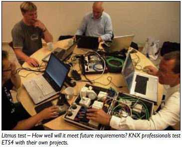
An international investigation was set up in order to optimise this new user interface, not only KNX professionals but also beginners with little or no KNX knowledge were consulted. System integrators with ETS3 expertise had the opportunity to try out the usefulness of the new features and at the same time the chance to give feedback based on their daily experience.
The tests with beginners were conducted to determine how intuitive the restructured work flows really are. In workshops held around the world, both professionals and beginners tested the tool on its daily usefulness in respect to maintaining projects quickly and offering highly demanding services.
The result of all of this research work is a stateof-the-art tool that meets the needs of a modern home and building control technology.
Highly visual interface
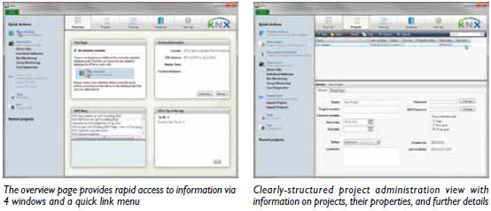
The tool’s new user interface is characterised by an up-todate, highly visual design. A new feature is for example an overview page, where users can view projects and access further information such as KNX news and the current ETS4 configuration. The project administration view, which shows project data and properties, is clearer than the ones from its predecessor.
The selective lists for opening databases, opening projects, importing data and viewing the most recently opened projects are together with the central toolbar, very useful features.
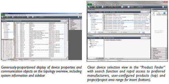
Initially ETS users – when working on projects – might miss the ‘old’ overview, because it’s no longer divided into three parts – topology view, group address view and building view. But professionals will quickly appreciate the simplified navigation and larger overviews of the “single window interface”. This is because of integrating various system views into one, crucial information is always visible and this without the need for additional menus.
In the topology overview for example, it only takes a mouse click via the line and device menu to quickly and easily reach communication objects, device details and comments. Important information can always be called via a sidebar. There is also a special Favourites window which can be personalised in order to quickly access customer-specific elements such as preconfigured devices or entire lines.
Intuitive
 Another advantage of the new ETS4 user interface is the “guided workflow” – a step by-step tutorial for creating bus configurations. Especially the topic-based Help features and the possibility to undo and repeat actions are very convenient.
System checks can be carried out at any time – this allows possible configuration errors to be detected quickly and in time. Drag & drop for e.g. assigning group addresses to communication objects, makes working with ETS4 yet even more intuitive. Thanks to the free-configurable views (dynamic folders), professionals can put together their own
interfaces in order to suit them to the way they work.
.
Related articles
10,008 views

International Standard - IEC 61850
The traditional approach to substation integration used standardized RTU protocols that were designed to provide protocol efficiency for operation over bandwidth limited serial links.
While such limitations remain for many applications, substation hardened equipment implementing modern networking standards like Ethernet now provide a cost effective means of enabling high speed communications within the substation.
To truly take advantage of this technology and dramatically lower the total cost of ownership of substation automation systems, a new approach to substation integration that goes beyond a simple RTU protocol is needed.
The recent international standard IEC 61850 proposes a unified solution of the communication aspect of substation automation. However, the standard itself is not easily understood by users other than domain experts. We present our understanding of the IEC 61850 standard as well as the design and implementation of our simulation tool in this report. Also, we give suggestions on the implementation of this standard based on our experience and lessons in the development of our simulation.
1. Introduction
Today, power substations are mostly managed by substation automation systems. These systems employ computers and domain specific applications to optimize the management of substation equipment and to enhance operation and maintenance efficiencies with minimal human intervention [8].
Once upon a time, substation automation systems utilized simple, straightforward and highly specialized communication protocols [7]. These protocols concerned less about the semantics of the exchanged data, data types of which were relatively primitive. Equipment was dumb and systems were simple. However, today’s substation automation systems can no longer enjoy such simplicity because of their growing complexity — equipment becomes more intelligent and most of those simple old systems have been gradually replaced by open systems, which embrace the advantage of emerging technology like relational database systems, multi-task operating systems and support for state-of-the-art graphical display technology.
Besides, devices from different manufacturers used different substation automation protocols [9, 3, 12], disabling them to talk to each other. Utilities have been paying enormous money and time to configure these devices to work together in a single substation. Today most utilities and device manufacturers have recognized the need for a unified international standard to support seamless cooperation among products from different vendors.
The IEC 61850 international standard, drafted by substation automation domain experts from 22 countries, seeks to tackle the aforementioned situation. This standard takes advantage of a comprehensive object-oriented data model and the Ethernet technology, bringing in great reduction of the configuration and maintenance cost. Unlike its predecessor, the Utility Communication Architecture protocol 2.0 (UCA 2.0) [12], the IEC 61850 standard is designed to be capable for domains besides substation automation. To make the new protocol less domain dependent, the standard committee endeavored to emphasize on the data semantics, carving out most of the communication details. This effort, however, could result in difficulties in understanding the standard.
In this research project, we aim to get a clear understanding of the IEC 61850 standard and simulate the protocol based on J-Sim [11]. Our ultimate goal is to investigate the security aspect about the IEC 61850 standard.
2 The IEC 61850 standard
The first release of the IEC 61850 consists of a set of documents of over 1,400 pages. These documents are divided into 10 parts, as listed in Table 1. Part 1 to Part 3 give some general ideas about the standard. Part 4 defines the project and management requirements in an IEC 61850 enabled substation. Part 5 specifies the required parameters for physical implementation. Part 6 defines an XML based language for IED configuration, presenting a formal view of the concepts in the standard. Part 7 elaborates on the logical concepts, which is further divided into four subparts (listed in Table 2). Part 8 talks about how to map the internal objects to the presentation layer and to the Ethernet link layer. Part 9 defines the mapping from sampled measurement value (SMV) to point-to-point Ethernet.
The last part gives instructions on conformance testing. Since Part 7 defines the core concepts of the IEC 61850 standard, we will focus on this part in this report.
| Subpart | Title |
| 7.1 | .Principles and Models |
| 7.2 | .Abstract Communication Service Interface |
| 7.3 | .Common Data Classes |
| 7.4 | .Compatible Logical Node Classes and Data Classes |
| Table 2: Subparts of IEC 61850-7 | |
The IEC 61850 standard is not easy to understand for people other than experts in the substation automation domain due to the complexity of the documents and the assumed domain-specific knowledge. Introductory documents on the standard abound [13, 4, 7, 5, 8, 2], but most of them are in the view of substation automation domain experts. Kostic et al. explained the difficulties they had in understanding the IEC 61850 standard [7].
In this section, we provide another experience of understanding this standard, trying to explain the major concepts of the IEC 61850 standard.
2.1 Challenges
Understanding the IEC 61850 standard proposes the following challenges for a outsider of the substation automation domain:
- As a substation automation standard proposed by a group of domain experts, the IEC 61850 protocol assumes quite an amount of domain-specific knowledge, which is hardly accessible by engineers and researchers out of the substation automation domain. To make things worse, the terms used in the standard is to some extent different from those commonly used in software engineering, bringing some difficulties for software engineers in reading the standard.
- The entire standard, except Part 6, is described in natural language with tables and pictures, which is known to be ambiguous and lack of preciseness. This situation is problematic because the IEC 61850 concepts are defined by more than 150 mutually relevant tables distributed over more than 1,000 pages. A formal presentation of all these concepts would be appreciated.
- The experts proposing this protocol come from 22 different countries and are divided into 10 working groups, each responsible to one part of the standard. Due to the different backgrounds and the informal presentation style of the standard, the standard contains a considerable number of inconsistencies. Such inconsistencies are more obvious for different parts of the standard, e.g. the data model described in Part 6 is clearly different from that described in Part 7.
- The standard committee made a great effort to describe the protocol in an object-oriented manner but the result is not so object-oriented. For example, the ACSI services are grouped by different classes, but reference to the callee object is not defined as a mandatory argument of the service function.
- The standard is designed to be implementation independent but this is not always true. For example, the data attribute TimeAccuracy in Part 7-2 Table 8 is defined as CODED ENUM, while what it virtually represents is a 5-bit unsigned integer; the frequent use of PACKED LIST (i.e. “bit fields” in the C language) also brings implementation details to interface design.
- Things are mixed up in the documents. Mandatory components and optional components are mixed in the standard, and domain independent concepts are mixed up with domain specific concepts. Even though the optional components and mandatory ones are marked with “O” and “M” alternatively, it would be a tough task to refine a model consisting only the mandatory components due to the implicit dependences between attributes in different tables and the conditional inclusion of some attributes. In fact, there are 29 common data classes and 89 compatible logical nodes defined in the standard, the relationship among which is unclear.
.
2.2 Intelligent electronic device
In the past, utility communication standards usually assumed some domain-specific background of the readers. Consequently, they contained a lot of implicit domain knowledge, which is hardly accessible to outsiders (e.g. software engineers) [7]. The IEC 61850 standard does not escape from this category. To help understanding the logical concepts of IEC 61850, we would like to lay a basic idea of intelligent electronic devices (IED), the essential physical object hosting all the logical objects.
Basically, the term intelligent electronic device refers to microprocessor-based controllers of power system equipment, which is capable to receive or send data/control from or to an external source [8]. An IED is usually equipped with one or more microprocessors, memory, possibly a hard disk and a collection of communication interfaces (e.g. USB ports, serial ports, Ethernet interfaces), which implies that it is essentially a computer as those for everyday use.
However, IEDs may contain some specific digital logics for domain-specific processing.
IEDs can be classified by their functions. Common types of IEDs include relay devices, circuit breaker controllers, recloser controllers, voltage regulators etc.. It should be noted that one IED can perform more than one functions, taking advantage of its general-purpose microprocessors. An IED may have an operating system like Linux running in it.
| Part | Title |
| 1 | .Introduction and Overview |
| 2 | .Glossary |
| 3 | .General Requirements |
| 4 | .System and Project Management |
| 5 | .Communication Requirements for Functions and Device .Models |
| 6 | .Configuration Description Language for Communication in .Electronic Substations Related to IEDs |
| 7 | .Basic Communication Structure for Substation and Feeder .Equipment |
| 8 | .Specific Communication Service Mapping (to MMS and to .Ethernet) |
| 9 | .Specific Communication Service Mapping (from Sampled .Values) |
| 10 | .Conformance Testing |
| Table 1: Parts of the IEC 61850 standard documents | |
2.3 Substation architecture
A typical substation architecture is shown in Figure 1. The substation network is connected to the outside wide area network via a secure gateway. Outside remote operators and control centers can use the abstract communication service interface (ACSI) defined in Part 7-2 to query and control devices in the substation. There is one or more substation buses connecting all the IEDs inside a substation. A substation bus is realized as a medium bandwidth Ethernet network, which carries all ACSI requests/responses and generic substation events messages (GSE, including GOOSE and GSSE).
There is another kind of bus called process bus for communication inside each bay. A process bus connects the IEDs to the traditional dumb devices (merge units, etc.) and is realized as a high bandwidth Ethernet network. A substation usually has only one global substation bus but multiple process buses, one for each bay.

Figure 1: Substation architecture
ACSI requests/responses, GSE messges and sampled analog values are the three major kinds of data active in the substation network. Since we are less interested in communication on the process buses (like sampled value multicasting), we focus on the activities on the substation bus in this report, especially the ACSI activities.
Interactions inside a substation automation system mainly fall into three categories: data gathering/setting, data monitoring/reporting and event logging.
The former two kinds of interactions are the most important — in the IEC 61850 standard all inquiries and control activities towards physical devices are modeled as getting or setting the values of the corresponding data attributes, while data monitoring/reporting provides an efficient way to track the system status, so that control commands can be issued in a timely manner.
To realize the above kinds of interaction, the IEC 61850 standard defines a relatively complicated communication structure, as is shown in Figure 2.

Figure 2: The communication profiles
Five kinds of communication profiles are defined in the standard: the abstract communication service interface profile (ACSI), the generic object oriented substation event profile (GOOSE), the generic substation status event profile (GSSE), the sampled measured value multicast profile (SMV), and the time synchronization profile. ACSI services enable client-server style interaction between applications and servers.
GOOSE provides a fast way of data exchange on the substation bus and GSSE provides an express way of substation level status exchange. Sample measured value multicast provides an effective way to exchange data on a process bus.
.
2.4 Abstract communication service interface
ACSI is the primary interface in the IEC 61850 standard not only because it is the interface via which applications talk with servers, but also in the sense that the ACSI communication channel is an important part of a logical connection between two logical nodes. ACSI defines the semantics of the data exchanged between applications and servers, thus it becomes the major part of the IEC 61850 standard.
The standard committee adopt an object-oriented approach in the design of ACSI, which includes a hierarchical and comprehensive data model and a set of available services for each class in this data model. Although the data model is usually described outside the scope of the ACSI, it is actually part of it. The benefits of using an object-oriented utility communication interface are two fold. On the one hand, objects (e.g. registers) can be referenced in an intuitive way (e.g. “Relay0/MMXU0.voltage”) instead of by the traditional physical address (like Reg#02432). On the other hand, software engineers can build more reliable applications using such service interface.
In the following two sections, we present a brief description on these two ACSI components.
.
2.5 Data model
The hierarchical data model defined in the IEC 61850 is depicted in Figure 3 and Figure 4.
Server is the topmost component in this hierarchy. It serves as the joint point of physical devices and logical objects. Theoretically one IED may host one or more server instances, but in practice usually only one server instance runs in an IED. A server instance is basically a program running in an IED, which shares the same meaning with other servers like FTP server etc.. Each server has one or more access points, which are the logical representation of a NIC. When a client is to access data or service of the server, it should connect to an access point of this server and establish a valid association.
Each server hosts several files or logical devices. Clients can manipulate files in the server like talking to a FTP server, which is usually used as a means to upload/update the configuration file of an IED. A logical device is the logical correspondence of a physical device. It is basically a group of logical nodes performing similar functions.
Functions supported by an IED are conceptually represented by a collection of primitive, atomic functional building blocks called logical nodes.
The IEC 61850 standard predefines a collection of template logical nodes (i.e. compatible logical nodes) in Part 7-4. Besides the regular logical nodes for functions, the standard also requires every logical device have two specific logical nodes: Logical Node Zero (LN0) and LPHD, which correspond to the logical device and the physical device, alternatively. Besides holding status information of the logical device, LN0 also provides additional functions like setting-group control, GSE control, sampled value control etc..
In the IEC 61850 standard, the entire substation system is modeled as a distributed system consisting of a collection of interacting logical nodes, which are logically connected by logical connections. It should be noted that the term logical connection refers to the logical concept of the connections between two logical nodes, which can be direct or indirect or even a combination of many different kinds of communication channels. In fact, the connection of two logical nodes is usually both indirect and a combination of TCP, UDP and direct Ethernet connections. We will explain logical connections in Section 2.9 (next article).
Data exchanged between logical nodes are modeled as data objects. A logical node usually contains several data objects. Each data object is an instance of the DATA class and has a common data class type.

Figure 3: Hierarchy of the IEC 61850 data model
Similar to the concept of objects in most object-oriented programming languages, a data object consists of many data attributes, which are instances of data attributes of the corresponding common data class. Data attributes are typed and restricted by some functional constraints. Instead of grouping data attributes by data objects, functional constraints provide a way to organize all the data attributes in a logical node by functions. Types of data attributes can be either basic or composite.
Basic types are primitive types in many programming languages, whereas composite types are composition of a collection of primitive types or composite types.
In the IEC 61850 standard, data attributes are at least as important as, if not more than, data objects for two reasons.

Figure 4: The data model of the IEC 61850
Firstly, data objects are just logical collections of the contained data attributes while (primitive) data attributes are the de facto logical correspondence to the physical entities (memory units, registers, communication ports, etc.); secondly, the purpose of data objects is for the convenience of managing and exchanging values of a group of data attributes sharing the same function.
Despite data objects, the IEC 61850 standard provides the concept of data set as another ways to manage and exchange a group of data attributes. Members of a data set can be data objects or data attributes. The concept of data set is somewhat similar to the concept of view in the area of database management systems.
In the IEC 61850 standard, most services involve data sets. Members in a data set unnecessarily come from the same logical node or the same data object, thus providing high flexibility of data management. Data sets are categorized into permanent ones and temporary ones.
Permanent data sets are hosted by logical nodes and will not be automatically deleted unless on the owners’ explicit requests; temporary data sets are exclusively hosted by the association having created them and will be automatically deleted when the association ends.
To be continued soon in next article: IEC 61850 in details (2)
SOURCE:
- Understanding and Simulating the IEC 61850 Standard by Yingyi Liang & Roy H. Campbell, Department of Computer Science University of Illinois at Urbana-Champaign
.


