
5,612 views

Siemens TechTopic | Bus Joint Fundamentals
Proper design of bus bar joints is a necessity for long equipment life. The objectives that a good bolted bus bar joint must fulfill include:
• It must provide good conductivity, so that the bus system will meet the temperature rise requirements in the ANSI standards.
• It must withstand thermal cycling, so that the low resistance joint will be maintained for the life of the equipment.
• The joint pressure should be high (for good conductivity), but not so high that cold flow of the bus material occurs, which would cause the joint to deteriorate with time.
•The joint should have good resistance to corrosion in normal installation environments.
• It must be able to withstand the mechanical forces and thermal stresses associated with short-circuit conditions.

Figure 1: Anatomy of a bolted bus bar joint
Figure 1 shows a bolted bus bar joint, simplified to show two bus bars connected using a single bolt. Except in rare situations, the bus bars are silver plated (standard) or tin plated (optional), to improve the resistance to corrosion. The bolt is a high strength grade 5 cap screw, while the nut is a grade 2 (heavy wall) nut. The joint includes a large diameter, thick flat washer on both sides of the joint, adjacent to the bus bars. A split lock washer is installed under the nut to assure that the joint stays tight over the life of the equipment.
Why do we use a grade 2 nut with a grade 5 bolt? The grade 2 nut is more ductile than the grade 5 bolt, so that when the nut is torqued in place, the threads in the nut will tend to be swaged down and burnished to a degree, which results in a more equal distribution of load on all threads. This spreads the force more evenly and avoids unacceptable stress levels in the bolt and the nut.
Some users request that special non-magnetic hardware be used in bus joints. Historically, particularly in open bus systems exposed to the weather, difficulties were encountered with corrosion, and this may be one reason that some still ask for non-magnetic hardware. Others prefer non-magnetic hardware because of the perception that it results in a lower temperature rise. While these reasons may have had merit decades ago, we feel they are unnecessary today. Non-magnetic hardware (usually stainless steel or silicon bronze) is expensive and difficult to obtain. In addition, the tensile strength and yield strength of non-magnetic hardware is lower than that of high strength steel, so that tightening torques will generally be lower with the special hardware. The net effect of lower torque and pressure may very well counterbalance any slight temperature rise benefit associated with non-magnetic hardware.
We also specify that the flat washers are to have larger diameter and greater thickness than standard washers. The purpose of the washers is to distribute the clamping force of the bolts over a wider area. To accomplish this, we need a washer that is relatively rigid, with a larger diameter than would be normal for the size bolt used. If a normal small diameter, thin washer (or worse, none at all) is used, the joint will deteriorate over time because of cold flow of copper from the high pressure region directly under the bolt head (or the nut).
.

Figure 2: Distribution of forces in a bolted bus bar joint
Figure 2 shows the distribution of forces in a bolted bus bar joint. To obtain a low resistance bus bar joint, we must establish and maintain sufficient pressure, and distribute the pressure over a large area. Initially, the two bus bars mate at only a few peaks or high spots. As the bolt is tightened, the bus conductors begin to deform, bringing more of these peaks into contact. At the design pressure, there is a relatively larger contact area, so that there are a multitude of parallel electrical connections between the bars.
As shown in figure 2, the force is concentrated more heavily around the bolt hole. Since the pressure is highest in the vicinity of the bolt hole, the surface irregularities in this area are flattened out as the mating surfaces are forced into more intimate contact. The joint resistance in this area will be lower than elsewhere in the joint. As distance from the bolt hole increases, pressure decreases and joint resistance increases. Beyond the area defined by the washer, pressure decreases rapidly and little effective current carrying capacity results.
From figure 2, we can see how the large diameter washers serve to distribute the clamping force more uniformly over a wider area than would be the case with a smaller washer, or none at all.
A properly designed bolted bus bar joint will allow the bus system to meet the temperature rise limits imposed by the ANSI standards, and will also have the thermal and mechanical capability to withstand the heat generated and forces imposed under the worst case short-circuit conditions.
.
SOURCE: T. W. (Ted) Olsen – Manager, Technology | Siemens Power Transmission & Distribution, Inc.
.
Related articles
16,594 views

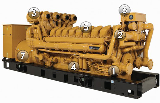
Caterpillar C175 Diesel Generator 2-4MW
The C175 family of diesel generator sets offers the most power you can get in any single high-speed package: 2-4MW.
One of the most significant components in the development of the C175 was the integration of ACERT™ Technology into the engine platform.
ACERT Technology is a synergistic approach utilizing a suite of complementary building block technologies that can be individually adapted to accommodate a specific application. In recent years, Caterpillar has spent more than $1 billion on the development of clean diesel technologies. Today, more than 330,000 engines are currently in operation with ACERT Technology, accumulating more than 2 million hours of use each day.
With the C175, the building blocks of ACERT Technology have been tailored to meet the current and pending emissions requirements of stationary diesel generator sets in a variety of applications.
Advantages
Thousands of hours of customer research created the foundation for the C175 design concept.
Some of the major advantages of the C175 family include:
- Proven Reliability with platform based on industry standard Cat® 3500 series, and supported by thousands of hours of lab and field-testing.
- Wider Power Range including 2000kW to 4000kW @ 1500 and 1800 rpm.
- Power Generation at Higher Speed than traditional medium speed products in the same power range.
- Higher Power Density equals more output from a given engine displacement / footprint, resulting in lower installed cost.
- Complete Package including SR5 generators, EMCP3 package controls and package/remote radiator with flexible controls packaging options simplifies installation.
- Lower Emissions meet U.S. EPA Tier 2 standards with a line of sight to meet U.S. EPA Tier 4 and EU Stage IIIB emissions levels.
- Lower Maintenance Costs due to increased oil change intervals, longer life (durability) of components and longer top end as well as full overhaul periods.
- Lower Operating Costs due to lower brake specific fuel consumption than competitive products.
- Systems Integration. The C175 electrical system components are engineered to work together with a wide range of products such as Uninterruptible Power Supplies (UPS), Automatic Transfer Switches (ATS), switchgear, remote monitoring services and customer building SCADA systems.
- Extensive Product Support from a worldwide dealer network with 24/7/365 parts and service availability.
Design Features
1. Fuel System

C175 - Fuel System
The new C175 engine features a Cat® Common Rail Fuel System designed specifically for this engine platform.
Full Control of Both Fuel Delivery and Fuel Pressure At Any Load or Speed results in superior transient response and block load acceptance, as well as shorter recovery time.
More Compact single camshaft that is used only to open the intake and exhaust valves. It features a simpler injection design with no pumping function necessary.
Improved Cold Start Capability uses higher pressures at low speeds and produces less smoke.
“Fluid Containment” Design. The high-pressure lines and rails are designed to provide outer concentric low-pressure containment. If a leak occurs in the high-pressure section, it leaks back to the outer low-pressure section and drains back to the tank.
Integrated Manifold or Monoblock offers a single point of connection to the engine, which eliminates leak paths while improving reliability.
Fuel Cooler Eliminated. Unlike the unit injector system, the Common Rail System used on the C175 does not require excess bypass fuel to cool the injector since injection pressure load is taken off the injector. The result is a reduction of heat generation in the return fuel and reduction in fuel flow rate by a factor of 4 when compared to the unit injector system. This eliminates the need for a fuel cooler in most cases.
Improved Fuel Filters. The C175 uses an eco-friendly fuel filter system. Instead of throwing away the whole canister, only the disposable non-metallic element inside the canister is changed.
Electronic Fuel Priming Pump is Engine Control Module (ECM)-controlled and offered as standard equipment. No manual effort is required to pump the fuel, so it’s more convenient and requires less operator effort.
2. Cooling System

C175 - Cooling System
The design philosophy for the Cat® C175 cooling system is to minimize heat rejection by cooling only the parts that require cooling.
Inlet-Regulated System. The C175 features an innovative design unique to Caterpillar. The system senses the temperature at the inlet and controls the output providing more consistent temperatures and better control of oil viscosity than an outlet-regulated system.
Electronic Fluid Temperature Controller regulates inlet temperature of the coolant and allows for troubleshooting without removing the thermostat. Improved diagnostics enable the operator to pinpoint a problem quickly, which increases reliability and uptime.
Integral Water Supply and Return Manifold are built into the engine block to minimize connection points and bolted joints. This design helps contain fluids and improves overall engine reliability and serviceability.
Two-Stage After-Cooler. The first stage is cooled by a jacket water circuit and the second stage has a two-pass separate circuit. The after-cooler is constructed with tube fin cores that are more robust compared to the traditional bar plate fin design. The tubes of the core can be cleaned without removing the core from the engine, and the core can be remanufactured. The tubes also have more surface area per volume and less pressure drop, resulting in more efficient cooling. This after-cooler design also minimizes the size of the SCAC circuit, thereby reducing the size of the radiator. The location of the first stage jacket water core provides protection from high air temperatures. These features improve the durability and reliability of the cooling system.
3. Air Management

C175 - Air Management
Air management is one of the ACERT™ Technology building blocks used on the Cat® C175 engine.
Crossflow Head provides separation between both the intake and exhaust ports and manifolds. The outboard air manifold location eliminates re-heating of intake air by preventing heat transfer from the exhaust to the intake. This results in reduced charge air temperature and increased charge air density, enabling higher power density as well as reducing SCAC cooling.
Taller Head accommodates larger ports and helps direct a large amount of cool air into the cylinder with the least resistance, resulting in the best port performance of any engine in the world. The taller head also accommodates increased valve lift of 22mm compared to 18mm on the Cat 3500, further improving breathing.
Improved Breathing. The tall crossflow head results in a greater amount of cooler air in and out of the engine, which helps produce higher power ratings and lower emissions. This, along with lower air pumping losses, results in lower fuel consumption.
New Generation of Turbochargers designed specifically for the C175. Four single-stage turbochargers provide a higher pressure ratio in a single stage. The turbocharger includes a cast titanium impeller and an improved bearing system that provides a higher load-bearing capacity and greater reliability, while increasing efficiency by 5% and extending the component life when compared to traditional cast aluminum impellers.
4. Lube System

C175 - Lube Management
The C175 lube system features two piston-cooling jets per piston.
A large capacity oil pump pressure regulation valve allows the engine to maintain optimum oil pressure at all speeds, loads and throughout the life of the engine, ultimately increasing durability.
.
.
.
5. Core Engine Components

C175 - Core Engine Components
The components of the new C175 centerline engine are designed for higher strength, durability and compactness.
Crankshaft has a larger diameter to handle bigger loads. It is made of steel forged material and features induction hardened fillets and journals. Thrust plates are located at the rear end of the crankshaft to reduce motion inside of the coupling between the engine and generator.
Block is made of cast iron and provides increased strength and stiffness, and is lighter weight.
Mid-Support Liners provide stronger support to the liner and offer more efficient cooling by only cooling the top 25% of the cylinder liner. Mid-support liners allow for a smaller inside diameter of the combustion seal, as well as a higher position for the piston’s top ring. The result is reduced crevice volume, improved cooling and combustion efficiency, and reduced emissions. Mid-support liners allow the head bolts to be closer to the cylinder bore to minimize cylinder spacing and to create a more compact engine.
Cylinder Cuff is specially designed for improved durability. The ring of the “cuff” located at the top of the cylinder scrapes off carbon accumulation on the piston top end, preventing the carbon from polishing, scratching or seizing the liner. The cuff also helps reduce crevice volume beside the piston, resulting in lower emissions.
Cylinder Head is made of iron for added strength. The tall C175 head helps eliminate the external water manifold by returning the coolant to the cylinder block.
Head Gasket features a simplified two-piece (carrier seal and combustion seal) design, shortening service time, decreasing parts costs, and increasing reliability and durability.
Pistons and Rings feature increased oil flow to pistons for better cooling and higher power ratings. Rectangular piston rings provide a superior seal and less motion, resulting in less wear and longer life. Piston, rod and liner come out as one assembly, resulting in faster, easier service.
Connecting Rods. Large diameter fracture split connecting rods provide better alignment between the rod and cap, which eliminates the need for a special alignment procedure.
Bearings. Large main and rod bearings provide better seizure resistance and better tolerance of a wide range of oil temperatures. Larger rod bearing and main bearing are more scuff and seizure resistant.
6. Engine Management System

C175 - Engine Management System
The Cat® C175 utilizes much of the ACERT™ Technology electronics experience gained on small-bore engines and employs many new improvements and technologies more useful on large bore engines. The C175 Engine Management System exploits the power of modern control technology to improve reliability, exceed customer expectations and accommodate future customer requirements.
Engine Control Module (ECM). C175 engine controls use the latest version of the ADEM™ A4 ECM to deliver 50 times the computing power of its predecessor. Specific benefits include monitoring over 30 points on the engine, driving up to 20 injectors, protecting the engine, communicating over 100 engine parameters to the customer, diagnosing and reporting on engine health. The ECM uses the latest advancements in ACERT Technology to improve engine performance while reducing emissions.
Engine Controls and Datalink. Three primary controllers are temperature control module, fuel high-pressure controller and ECM. These are connected to the engine J1939 datalink.
Rigid Wiring Harness. Metal enclosed rigid wiring harness system protects critical engine circuits from accidental damage, reducing service calls and increasing reliability.
Controls Packaging. The standard panel is a rear-mounted EMCP 3.1 with the option to upgrade to the EMCP 3.2 or EMCP 3.3.
7. Generator

C175 - Generator
Caterpillar is introducing the next evolution of generators, the SR5 Series, with the introduction of the C175 generator sets. The SR5 Series 1800 and 3000 frame generators have been designed specifically to work with the C175 engines. The structural design is matched to the C175 engine. Torsional and linear vibration analysis and testing have been performed to ensure durability.
The SR5 generator’s insulation system has been improved to meet insulation Class H. SR5 generators feature 2/3-pitch as standard on all low, medium and high voltage generators. SR5 generators have IP23 particle ingress protection.
Generator Set Packaging. The C175 uses a fusible coupling to connect the generator to the engine. All engines, generators and controls are tested individually prior to assembly. Once assembled, the entire generator set package is tested before shipping to dealers to ensure quality.
Applications
The versatility of the C175 makes it ideal for a variety of applications.
- Continuous – A continuous rating has a typical load factor of 70% to 100% with no limit on the number of hours per year. Typical peak demand is 100% of continuous rated kW for 100% of operating hours. Typical applications include base load, utility or co-generation.
- Prime – A prime rating has a typical load factor of 60% to 70% with no limit on the number of hours per year. Typical peak demand is 100% of prime rated kW with 10% overload available for emergency use for up to one hour in 12. Typical applications include industrial, pumping, construction, peak shaving or co-generation.
- Standby – A standby rating has a typical load factor of 70% or less with variable load for about 200 hours per year,with a maximum expected usage of 500 hours per year. Typical peak demand is 80% of the standby rated kW with power available for the duration of an emergency outage. Typical applications include building service standby or emergency standby.
- Load Management – A load management rating has a typical load factor of 100% of the prime rating for a maximum of 500 hours per year. Typical peak demand is 100% of the load management rating, with no overload available. Typical applications include base load or peak shaving.
SOURCE: Caterpillar C175
.
Related articles
4,875 views

Hydropower - Systems Overview
Continued from first part of article:
Hydropower – Systems Overview (1)
Generator
The generator converts the rotational energy from the turbine shaft into electricity.
Efficiency is important at this stage too, but most modern, well-built generators deliver good efficiency.
Direct current (DC) generators, or alternators with rectifiers, are typically used with small household systems, and are usually augmented with batteries for reserve capacity, as well as inverters for converting the electricity into the AC required by most appliances. DC generators are available in a variety of voltages and power outputs.
AC generators are typically used with systems producing about 3 KW or more. AC voltage is also easily changed using transformers, which can improve efficiency with long transmission lines.
 Pelton wheel. Peltons vary in size from 3 inches to 13 feet or more, depending on head and flow.")
A view into a turbine shows a relatively large (2 feet in diameter) Pelton wheel. Peltons vary in size from 3 inches to 13 feet or more, depending on head and flow.
Depending on your requirements, you can choose either single-phase or three-phase AC generators in a variety of voltages. One critical aspect of AC is frequency, typically measured as cycles per second (cps) or Hertz (Hz).
Most household appliances and motors run on either 50 Hz or 60 Hz (depending on where you are in the world), as do the major grids that interconnect large generating stations. Frequency is determined by the rotational speed of the generator shaft; faster rotation generates a higher frequency.
In battery-based hydro systems, the inverter produces an AC waveform at a fixed frequency. In batteryless hydro systems, the turbine controller regulates the frequency.
AC Controls

At the bottom of the penstock, a manifold routes water to the four nozzles of a Harris Pelton turbine that drives a permanent magnet alternator.
Pure AC hydro systems have no batteries or inverter. AC is used by loads directly from the generator, and surplus electricity is burned off in dump loads—usually resistance heaters.
Governors and other controls help ensure that an AC generator constantly spins at its correct speed. The most common types of governors for small hydro systems accomplish this by managing the load on the generator. With no load, the generator would “freewheel,” and run at a very high rpm. By adding progressively higher loads, you can eventually slow the generator until it reaches the exact rpm for proper AC voltage and frequency.
As long as you maintain this “perfect” load, known as the design load, electrical output will be correct. You might be able to maintain the correct load yourself by manually switching devices on and off, but a governor can do a better job— automatically.
By connecting your hydro system to the utility grid, you can draw energy from the grid during peak usage times when your hydro system can’t keep up, and feed excess electricity back into the grid when your usage is low. In effect, the grid acts as a large battery with infinite capacity.
If you choose to connect to the grid, however, keep in mind that significant synchronization and safeguards must be in place. Grid interconnection controls do both. They will monitor the grid and ensure that your system is generating compatible voltage, frequency, and phase. They will also instantly disconnect from the grid if major fluctuations occur on either end. Automatic disconnection is critical to the safety of all parties. At the same time, emergency shutdown systems interrupt the water flow to the turbine, causing the system to coast to a stop, and protecting the turbine from overspeed.
DC Controls
A DC hydro system works very differently from an AC system. The alternator or generator output charges batteries. A diversion controller shunts excess energy to a dump load. An inverter converts DC electricity to AC electricity for home use. DC systems make sense for smaller streams with potential of less than 3 KW.
AC systems are limited to a peak load that is equivalent to the output of the generator. With a battery bank and large inverter, DC systems can supply a high peak load from the batteries even though the generating capacity is lower.
Series charge controllers, like those used with solar- electric systems, are not used with hydro systems since the generators cannot run without a load (open circuit). This can potentially damage the alternator windings and bearings from overspeeding. Instead, a diversion (or shunt) controller must be used. These normally divert energy from the battery to a resistance heater (air or water), to keep the battery voltage at the desired level while maintaining a constant load on the generator.
The inverter and battery bank in a DC hydro system are exactly the same as those used in battery-based, solar-electric or wind-electric systems. No other special equipment is needed. Charge controller settings may be lower than used in typical PV and wind systems, since hydro systems are constant and tend to run with full batteries much of the time.
Head, Flow, & Efficiency
If you expect to sell electricity back to the utility, pay extra attention to the efficiency of your hydro system because higher output and a lower cost-per-watt will go straight to your bottom line. Your turbine manufacturer can give you guidance on the most efficient design, as well as grid interconnection controls and safeguards. If you’re off- grid, and your site doesn’t have lots of head and flow, high efficiency can make the difference between ample electricity for your needs and having to use a backup, gasoline- powered generator.
| Click on turbine images to see enlarged: | ||||||
 A Canadian-made Energy Systems and Design turbine uses a permanent magnet alternator and a turgo runner. |  A Power Pal turbine with a Francis runner direct-coupled to the alternator |  turgo runner in an Australian-made Platypus turbine.") The 4-inch (10 cm) turgo runner in an Australian-made Platypus turbine. |  The underside of a low-head, high-flow Nautilus turbine showing the Francis runner, and above it, the innovative nautilus-shaped headrace. | |||
Whether a hydro system generates a few watts or hundreds of megawatts, the fundamentals are the same. Head and flow determine how much raw water power is available, and the system efficiency affects how much electricity will come out the other end. Each component of a hydro system affects efficiency, so it’s worthwhile to optimize your design every step of the way.
More Hydro Terms
| Pipe Loss | Pressure | Reaction Turbine | Runner | |||
| Frictional Head Loss: Refers to the quantity of water supplied from a water source or exiting a nozzle per unit of time. Commonly measured in gallons per minute (gpm). | A type of reaction hydro-turbine used in low to medium heads. It consists of fixed vanes on a shaft. Water flows down through the vanes, driving the shaft. | Lost energy due to pipe friction. In hydro systems, pipe sized too small can lead to serious friction losses. | The difference in elevation between a source of water and the location at which the water from that source may be used (synonym: vertical drop). Expressed in vertical distance or pressure. | |||
| Tailrace | Trash Rack | Turgo | ||||
| A flume or channel that feeds water into a hydro turbine. | Any electricity that is generated by the flow of water. | Turbines with runners that operate in air, driven by one or more high-velocity jets of water from nozzles. Typically used with moderate- to high- head systems. Examples include Pelton and turgo. | ||||
SOURCE: Dan New, homepower.com
.
Related articles

What CB to use? Vacuum or SF6 circuit breaker?
Until recently oil circuit breakers were used in large numbers for Medium voltage Distribution system in many medium voltage switchgears. There are number of disadvantages of using oil as quenching media in circuit breakers. Flammability and high maintenance cost are two such disadvantages! Manufacturers and Users were forced to search for different medium of quenching. Air blast and Magnetic air circuit breakers were developed but could not sustain in the market due to other disadvantages associated with such circuit breakers. These new types of breakers are bulky and cumbersome. Further research were done and simultaneously two types of breakers were developed with SF6 as quenching media in one type and Vacuum as quenching media in the other. These two new types of breakgasers will ultimately replace the other previous types completely shortly. There are a few disadvantages in this type of breakers also. One major problem is that the user of the breakers are biased in favour of old fashioned oil circuit breakers and many of the users always have a step motherly attitude to the new generations of the breakers. However in due course of time this attitude will disappear and the new type of breakers will get its acceptance among the users and ultimately they will completely replace the oil circuit breakers. An attempt is made to make a comparison between the SF6 type and vacuum type circuit breakers with a view to find out as to which of the two types is superior to the other. We will now study in detail each type separately before we compare them directly.
Vacuum Circuit Breaker

Evolis MV Circuit Breaker
In a Vacuum circuit breaker, vacuum interrupters are used for breaking and making load and fault currents. When the contacts in vacuum interrupter separate, the current to be interrupted initiates a metal vapour arc discharge and flows through the plasma until the next current zero. The arc is then extinguished and the conductive metal vapour condenses on the metal surfaces within a matter of micro seconds. As a result the dielectric strength in the breaker builds up very rapidly.
The properties of a vacuum interrupter depend largely on the material and form of the contacts. Over the period of their development, various types of contact material have been used. At the moment it is accepted that an oxygen free copper chromium alloy is the best material for High voltage circuit breaker. In this alloy , chromium is distributed through copper in the form of fine grains. This material combines good arc extinguishing characteristic with a reduced tendency to contact welding and low chopping current when switching inductive current. The use of this special material is that the current chopping is limited to 4 to 5 Amps.
At current under 10KA, the Vacuum arc burns as a diffuse discharge. At high values of current the arc changes to a constricted form with an anode spot. A constricted arc that remain on one spot for too long can thermically over stress the contacts to such a degree that the deionization of the contact zone at current zero can no longer be guaranteed . To overcome this problem the arc root must be made to move over the contact surface. In order to achieve this, contacts are so shaped that the current flow through them results in a magnetic field being established which is at right angles to the arc axis. This radial field causes the arc root to rotate rapidly around the contact resulting in a uniform distribution of the heat over its surface. Contacts of this type are called radial magnetic field electrodes and they are used in the majority of circuit breakers for medium voltage application.
A new design has come in Vacuum interrupter, in which switching over the arc from diffusion to constricted state by subjecting the arc to an axial magnetic field. Such a field can be provided by leading the arc current through a coil suitably arranged outside the vacuum chamber. Alternatively the field can be provided by designing the contact to give the required contact path. Such contacts are called axial magnetic field electrodes. This principle has advantages when the short circuit current is in excess of 31.5 KA.
SF6 Gas Circuit Breaker

SF6 circuit breakers
In an SF6 circuit-breaker, the current continues to flow after contact separation through the arc whose plasma consists of ionized SF6 gas. For, as long as it is burning, the arc is subjected to a constant flow of gas which extracts heat from it. The arc is extinguished at a current zero, when the heat is extracted by the falling current. The continuing flow of gas finally de-ionises the contact gap and establishes the dielectric strength required to prevent a re-strike.
The direction of the gas flow, i.e., whether it is parallel to or across the axis of the arc, has a decisive influence on the efficiency of the arc interruption process. Research has shown that an axial flow of gas creates a turbulence which causes an intensive and continuous interaction between the gas and the plasma as the current approaches zero. Cross-gas-flow cooling of the arc is generally achieved in practice by making the arc move in the stationary gas. This interruption process can however, lead to arc instability and resulting great fluctuations in the interrupting capability of the circuit breaker.
In order to achieve a flow of gas axially to the arc a pressure differential must be created along the arc. The first generation of the SF6 circuit breakers used the two-pressure principle of the air-blast circuit-breaker. Here a certain quantity of gas was kept stored at a high pressure and released into the arcing chamber. At the moment high pressure gas and the associated compressor was eliminated by the second generation design. Here the pressure differential was created by a piston attached to the moving contacts which compresses the gas in a small cylinder as the contact opens. A disadvantage is that this puffer system requires a relatively powerful operating mechanism.
Neither of the two types of circuit breakers described was able to compete with the oil circuit breakers price wise. A major cost component of the puffer circuit-breaker is the operating mechanism; consequently developments followed which were aimed at reducing or eliminating this additional cost factor. These developments concentrated on employing the arc energy itself to create directly the pressure-differential needed. This research led to the development of the self-pressuring circuit-breaker in which the over – pressure is created by using the arc energy to heat the gas under controlled conditions. During the initial stages of development, an auxiliary piston was included in the interrupting mechanism, in order to ensure the satisfactory breaking of small currents. Subsequent improvements in this technology have eliminated this requirement and in the latest designs the operating mechanism must only provide the energy needed to move the contacts.
Parallel to the development of the self-pressuring design, other work resulted in the rotating – arc SF6 gas circuit breaker. In this design the arc is caused to move through, in effect the stationery gas. The relative movement between the arc and the gas is no longer axial but radial, i.e., it is a cross-flow mechanism. The operating energy required by circuit breakers of this design is also minimal.
Table 1. Characteristics of the SF6 and vacuum current interrupting technologies.
| SF6 Circuit Breakers | Vacuum Circuit Breakers | ||
| Criteria | Puffer Circuit Breaker | Self-pressuring circuit-breaker | Contact material-Chrome-Copper |
| Operating energy requirements | Operating Energy requirements are high, because the mechanism must supply the energy needed to compress the gas. | Operating Energy requirements are low, because the mechanism must move only relatively small masses at moderate speed, over short distances. The mechanism does not have to provide the energy to create the gas flow | Operating energy requirements are low, because the mechanism must move only relatively small masses at moderate speed, over very short distances. |
| Arc Energy | Because of the high conductivity of the arc in the SF6 gas, the arc energy is low. (arc voltage is between 150 and 200V.) | Because of the very low voltage across the metal vapour arc, energy is very low. (Arc voltage is between 50 and 100V.) | |
| Contact Erosion | Due to the low energy the contact erosion is small. | Due to the very low arc energy, the rapid movement of the arc root over the contact and to the fact that most of the metal vapour re-condenses on the contact, contact erosion is extremely small. | |
| Arc extinguishing media | The gaseous medium SF6 possesses excellent dielectric and arc quenching properties. After arc extinction, the dissociated gas molecules recombine almost completely to reform SF6. This means that practically no loss/consumption of the quenching medium occurs. The gas pressure can be very simply and permanently supervised. This function is not needed where the interrupters are sealed for life. | No additional extinguishing medium is required. A vacuum at a pressure of 10-7 bar or less is an almost ideal extinguishing medium. The interrupters are ‘sealed for life’ so that supervision of the vacuum is not required. | |
| Switching behavior in relation to current chopping | The pressure build-up and therefore the flow of gas is independent of the value of the current. Large or small currents are cooled with the same intensity. Only small values of high frequency, transient currents, if any, will be interrupted. The de-ionization of the contact gap proceeds very rapidly, due to the electro-negative characteristic of the SF6 gas and the arc products. | The pressure build-up and therefore the flow of gas is dependent upon the value of the current to be interrupted. Large currents are cooled intensely, small currents gently. High frequency transient currents will not, in general, be interrupted. The de-ionization of the contact gap proceeds very rapidly due to the electro-negative characteristic of the SF6 gas and the products. | No flow of an ‘extinguishing’ medium needed to extinguish the vacuum arc. An extremely rapid de-ionization of the contact gap, ensures the interruption of all currents whether large or small. High frequency transient currents can be interrupted. The value of the chopped current is determined by the type of contact material used. The presence of chrome in the contact alloy with vacuum also. |
| No. of short-circuit operation | 10—50 | 10—50 | 30—100 |
| No. full load operation | 5000—10000 | 5000—10000 | 10000—20000 |
| No. of mechanical operation | 5000—20000 | 5000—20000 | 10000—30000 |
Comparison of the SF6 And Vacuum Technologies
The most important characteristics of the SF6 gas and vacuum-circuit breakers, i.e., of SF6 gas and vacuum as arc-extinguishing media are summarized in Table-1.
In the case of the SF6 circuit-breaker, interrupters which have reached the limiting number of operations can be overhauled and restored to ‘as new’ condition. However, practical experience has shown that under normal service conditions the SF6 interrupter never requires servicing throughout its lifetime. For this reason, some manufacturers no longer provide facilities for the user to overhaul the circuit-breaker, but have adopted a ‘sealed for life’ design as for the vacuum-circuit breaker.
The operating mechanisms of all types of circuit-breakers require servicing, some more frequently than others depending mainly on the amount of energy they have to provide. For the vacuum-circuit breaker the service interval lies between 10,000 and 20,000 operations. For the SF6 designs the value varies between 5,000 and 20,000 whereby, the lower value applies to the puffer circuit-breaker for whose operation, the mechanism must deliver much more energy.
The actual maintenance requirements of the circuit-breaker depend upon its service duty, i.e. on the number of operations over a given period of time and the value of current interrupted. Based on the number of operations given in the previous section, it is obvious that SF6 and vacuum circuit-breakers used in public supply and /or industrial distribution systems will, under normal circumstances, never reach the limits of their summated breaking current value. Therefore, the need for the repair or replacement of an interrupter will be a rare exception and in this sense these circuit-breakers can be considered maintenance-free. Service or maintenance requirements are therefore restricted to routine cleaning of external surfaces and the checking and lubrication of the mechanism, including the trip-linkages and auxiliary switches. In applications which require a very high number of circuit-breaker operations e.g. for arc furnace duty or frequently over the SF6 design, due to its higher summated-breaking current capability. In such cases it is to be recommended that the estimation of circuit-breaker maintenance costs be given some consideration and that these be included in the evaluation along with the initial, capital costs.
Reliability
In practice, an aspect of the utmost importance in the choice of a circuit-breaker is reliability.
The reliability of a piece of equipment is defined by its mean time to failure (MTF), i.e. the average interval of time between failures. Today, the SF6 and vacuum circuit-breakers made use of the same operating mechanisms, so in this regard they can be considered identical.
However, in relation to their interrupters the two circuit breakers exhibit a marked difference. The number of moving parts is higher for the SF6 circuit-breaker than that for the vacuum unit. However, a reliability comparison of the two technologies on the basis of an analysis of the number of components are completely different in regards design, material and function due to the different media. Reliability is dependent upon far too many factors, amongst others, dimensioning, design, base material, manufacturing methods, testing and quality control procedures, that it can be so simply analyzed.
In the meantime, sufficient service experience is available for both types of circuit-breakers to allow a valid practical comparison to be made. A review of the available data on failure rates confirms that there is no discernible difference in reliability between the two circuit-breaker types. More over, the data shows that both technologies exhibit a very high degree of reliability under normal and abnormal conditions.
Switching of fault currents
Today, all circuit-breakers from reputable manufacturers are designed and type-tested in conformance with recognized national or international standards (IEC56). This provides the assurance that these circuit-breakers will reliably interrupt all fault currents up to their maximum rating. Further, both types of circuit-breakers are basically capable of interrupting currents with high DC components; such currents can arise when short circuits occur close to a generator. Corresponding tests have indeed shown that individual circuit-breakers of both types are in fact, capable of interrupting fault currents with missing current zeros i.e. having a DC component greater than 100 per cent. Where such application is envisaged, it is always to be recommended that the manufacturer be contacted and given the information needed for a professional opinion.
As regards the recovery voltage which appears after the interruption of a fault current the vacuum-circuit breaker can, in general, handle voltages with RRV values of up to 5KV. SF6 circuit-breakers are more limited, the values being in the range from 1 to 2 KV. In individual applications, e.g. in installations with current limiting chokes or reactors, etc., With SF6 circuit-breakers it may be advisable or necessary to take steps to reduce that rate of rise of the transient recovery voltage.
Switching small inductive currents
The term, small inductive currents is here defined as those small values of almost pure inductive currents, such as occur with unloaded transformers, motor during the starting phase or running unloaded and reactor coils. When considering the behavior of a circuit-breaker interrupting such currents, it is necessary to distinguish between high frequency and medium frequency transient phenomena.
Medium frequency transients arise from, amongst other causes, the interruption of a current before it reaches its natural zero. All circuit-breakers can, when switching currents of the order of a few hundred amperes and, due to instability in the arc, chop the current immediately prior to a current zero.
This phenomenon is termed real current chopping. When it occurs, the energy stored in the load side inductances oscillates through the system line to earth capacitances (winding and cable capacitances) and causes an increase in the voltage. This amplitude of the resulting over voltage is a function of the value of the current chopped. The smaller the chopped current, the lower the value of the over voltage.
In addition to the type of circuit – breaker, the system parameters at the point of installation are factors which determine the height of the chopping current, in particular the system capacitance parallel to the circuit breaker is of importance. The chopping current of SF6 circuit-breakers is essentially determined by the type of circuit-breaker. The value of chopping current varies from 0.5A to 15A, whereby the behavior of the self – pressuring circuit-breaker is particularly good, its chopping current being less than 3A.This ‘soft’
Switching feature is attributable to the particular characteristics of the interrupting mechanism of the self-pressuring design and to the properties of the SF6 gas itself.
In the early years of the development of the vacuum circuit-breaker the switching of small inductive currents posed a major problem, largely due to the contact material in use at that time. The introduction of the chrome copper contacts brought a reduction of the chopping current to between 2 to 5A.The possibility of impermissible over voltages arising due to current chopping has been reduced to a negligible level.
High frequency transients arise due to pre- or re-striking of the arc across the open contact gap. If, during an opening operation, the rising voltage across the opening contacts, exceed the dielectric strength of the contact gap , a re-strike occurs. The high-frequency transient current arising from such a re-strike can create high frequency current zeros causing the circuit-breaker to, interrupt again. This process can cause a further rise in voltage and further re-strikes. Such an occurrence is termed as multiple restriking.
With circuit- breakers that can interrupt high frequency transient currents, re-striking can give rise to the phenomenon of virtual current chopping. Such an occurrence is possible when a re-strike in the first-phase-to-clear, induces high frequency transients in the other two phases, which are still carrying service frequency currents. The superimposition of this high frequency oscillation on the load current can cause an apparent current zero and an interruption by the circuit-breaker, although the value of load current may be quite high. This phenomenon is called virtual current chopping and can result in a circuit breaker ‘chopping’ very much higher values of current than it would under normal conditions. The results of virtual current chopping are over-voltages of very high values.
This phenomenon is termed real current chopping. When it occurs, the energy Stored in the load side inductances oscillates through the system line to earth capacitances (winding and cable capacitances) and causes an increase in the voltage. This amplitude of the resulting over voltage is a function of the value of the current chopped. The smaller the chopped current, the lower the value of the over voltage.
In addition to the type of circuit – breaker, the system parameters at the point of installation are factors which determine the height of the chopping current, in particular the system capacitance parallel to the circuit breaker is of importance. The chopping current of SF6 circuit-breakers is essentially determined by the type of circuit-breaker. The value of chopping current varies from 0.5A to 15A, whereby the behaviour of the self – pressuring circuit-breaker is particularly good, its chopping current being less than 3A.This ‘soft’ Switching feature is attributable to the particular characteristics of the interrupting mechanism of the self-pressuring design and to the properties of the SF6 gas itself.
In the early years of the development of the vacuum circuit-breaker the switching of small inductive currents posed a major problem, largely due to the contact material in use at that time. The introduction of the chrome copper contacts brought a reduction of the chopping current to between 2 to 5A.The possibility of impermissible over voltages arising due to current chopping has been reduced to a negligible level.
High frequency transients arise due to pre- or re-striking of the arc across the open contact gap. If, during an opening operation, the rising voltage across the opening contacts exceeds the dielectric strength of the contact gap, a re-strike occurs. The high-frequency transient current arising from such a re-strike can create high frequency current zeros causing the circuit-breaker to, interrupt again. This process can cause a further rise in voltage and further re-strikes. Such an occurrence is termed as multiple re-striking.
With circuit- breakers that can interrupt high frequency transient currents, re-striking can give rise to the phenomenon of virtual current chopping. Such an occurrence is possible when a re-strike in the first-phase-to-clear, induces high frequency transients in the other two phases, which are still carrying service frequency currents. The superimposition of this high frequency oscillation on the load current can cause an apparent current zero and an interruption by the circuit-breaker, although the value of load current may be quite high. This phenomenon is called virtual current chopping and can result in a circuit breaker ‘chopping’ very much higher values of current than it would under normal conditions. The results of virtual current chopping are over-voltages of very high values
Table2. Comparison of the SF6 And Vacuum Technologies In Relation To Operational Aspects
| Criteria | SF6 Breaker | Vacuum Circuit Breaker |
| Summated current cumulative | 10-50 times rated short circuit current | 30-100 times rated short circuit current |
| Breaking current capacity of interrupter | 5000-10000 times | 10000-20000 times |
| Mechanical operating life | 5000-20000 C-O operations | 10000-30000 C-O operations |
| No operation before maintenance | 5000-20000 C-O operations | 10000-30000 C-O operations |
| Time interval between servicing Mechanism | 5-10 years | 5-10 years |
| Outlay for maintenance | Labour cost High, Material cost Low | Labour cost Low, Material cost High |
| Reliability | High | High |
| Dielectric withstand strength of the contact gap | High | Very high |
Very extensive testing has shown that, because of its special characteristics the SF6 self-pressuring circuit-breaker possesses considerable advantages in handling high frequency transient phenomena, in comparison with both the puffer type SF6 and the vacuum circuit breakers. The past few years have seen a thorough investigation of the characteristics of vacuum circuit breakers in relation to phenomena such as multiple re-striking and virtual current chopping. These investigations have shown that the vacuum circuit-breaker can indeed cause more intense re-striking and hence more acute over voltages than other types. However, these arise only in quite special switching duties such as the tripping of motors during starting and even then only with a very low statistical probability. The over-voltages which are created in such cases can be reduced to safe levels by the use of metal oxide surge diverters.
Table3. Comparison of the SF6 And Vacuum Switching Technologies In Relation To Switching Applications
| Criteria | SF6 Circuit Breaker | Vacuum Circuit Breaker |
| Switching of Short circuit current with High DC component | Well suited | Well suited |
| Switching of Short circuit current with High RRV | Well suited under certain conditions (RRV>1-2 kV per Milli seconds | Very well suited |
| Switching of transformers | Well suited. | Well suited |
| Switching of reactors | Well suited | Well suited. Steps to be taken when current <600A. to avoid over voltage due to current chopping |
| Switching of capacitors | Well suited. Re-strike free | Well suited. Re-strike free |
| Switching of capacitors back to back | Suited. In some cases current limiting reactors required to limit inrush current | Suited. In some cases current limiting reactors required to limit inrush current |
| Switching of arc furnace | Suitable for limited operation | Well suited. Steps to be taken to limit over voltage. |
.


