
3,943 views

Arc-resistant low voltage switchgear
For years, electrical equipment has been designed to withstand and deal with the issue of bolted faults, where the current spikes to a dangerously high level but is safely interrupted by the protective devices contained in the equipment (breakers, fuses and relays). However, these devices typically do not detect and interrupt dangerous internal arcing faults, which have a lower current level, but can generate a far more dangerous scenario for operating personnel.
Arc faults can be caused by a breakdown of insulation materials, objects coming into close proximity with the energized bus assembly, even entry of rodents or other animals into the equipment. The thermal energy created by these events can get as high as 35,000ºF, melting materials and clothing from several feet away. Also consider that the arc blast produced by a lineup of 480 Vac switchgear rated at 85 kA can be equivalent to 20.7 lbs of TNT!
.
So, what is the solution?
Eaton’s solution: arc-resistant low voltage switchgear
Eaton introduces the addition of an ANSI Type 2 arc-resistant low voltage switchgear offering to its current product line. This is the latest release in arc-safe equipment from Eaton’s Electrical Sector. The arc-resistant low voltage switchgear protects operating and maintenance personnel from dangerous arcing faults
by redirecting or channeling the arc energy out the top of the switchgear, regardless of the origination location of the arc.
Eaton’s arc-resistant low voltage switchgear has been successfully tested to ANSI C37.20.7 at KEMA-Powertest, and has been ULT witnessed and certified.
Standard features
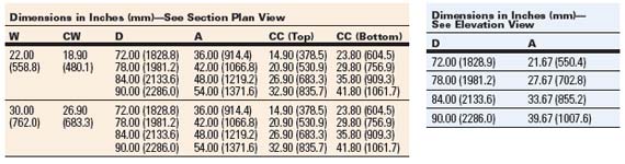
- Ratings:
- Up to 100 kA short circuit at 508 Vac maximum and up to 85 kA short circuit at 635 Vac maximum
- Up to 10 kA horizontal main bus continuous current
- Up to 5 kA vertical bus continuous current
- MagnumE DS power circuit breaker frame ratings between 800A and 6000A
- ANSI Type 2 arc-resistant design protects the operator around the entire perimeter of the equipment
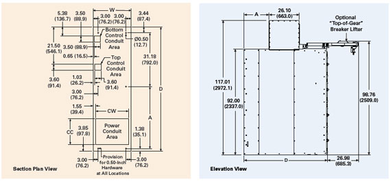
- Floor-to-ceiling height of 10 feet required whether exhausting into a room or through an arc plenum
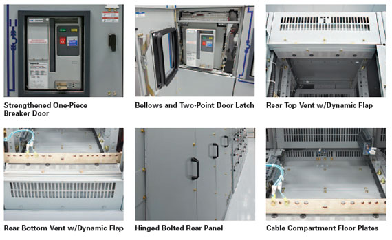
- Strengthened one-piece breaker door and latches
- Dynamic flap system on rear ventilation openings that remain open under normal operating conditions, but close during an arcing event to prevent dangerous gasses from escaping
- Patented bellows design allowing drawout of breaker into the disconnected position with the door closed, while simultaneously protecting the operator from any dangerous gasses during an arc event
- Patented venting system that directs arc gasses out the top of the enclosure, regardless of the arc origination location
- Up to four-high breaker configuration with no additional layout restrictions
- Strengthened side and rear panels with standard split rear covers for cable access
- NEMAT 1 enclosure, with either top or bottom cable or bus duct entry
- Cable compartment floor plates
Optional features
- Zone selective interlocking protection
- ANSI Type 2B arc-resistant design protects the operator even with the low voltage instrument compartment door open
- Arcflash Reduction Maintenance SystemE
- Safety shutters
- One-piece hinged and bolted rear panel
- Insulated bus
- Vented bus/cable compartment barrier
- Cable compartment segregation barrier
Benefits
- Superior protection against arcs in breaker, bus or cable compartments
- No increase in footprint over regular Magnum DS switchgear
- Closed door racking
Standards
- UL 1558 and UL 891
- ANSI C37.20.1, ANSI C37.13, ANSI C37.51 and ANSI C37.20.7
- CSAT standard—CSA C22.2 No. 31-04
- Third-party (UL/CSA) witness tested
- Seismic certification 2006-IBC
Testing
Testing procedures were completed per ANSI C37.20.7 standards with arcs initiated in:
- Breaker compartment
- Vertical and horizontal bus
- Cable termination compartments
Additionally, the tested arc duration was up to the full 0.5 seconds recommended by ANSI C37.20.7, with no dependence on the tripping speed of an upstream breaker.
.
Related articles
22,470 views

Standard IEC 60947-2 | Circuit Breakers
This standard applies to circuit-breakers, the main contacts of which are intended to be connected to circuits, the rated voltage of which does not exceed 1000 VAC or 1500 VDC.; it also contains additional requirements for integrally fused circuit-breakers.
It applies whatever the rated currents, the method of construction or the proposed applications of the circuit-breakers may be.
Changes in dependability needs and technologies have led to a marked increase in standard requirements for industrial circuit-breakers.
Conformity with standard IEC 947-2, renamed IEC 60947-2 in 1997, can be considered as an ‘all-risk’ insurance for use of circuit-breakers. This standard has been approved by all countries.
The principles
Standard IEC 60947-2 is part of a series of standards defining the specifications for LV electrical switchgear:
- the general rules IEC 60947-1, that group the definitions, specifications and tests common to all LV industrial switchgear.
- the product standards IEC 60947-2 to 7, that deal with specifications and tests specific to the product concerned. Standard IEC 60947-2 applies to circuit-breakers and their associated trip units. Circuit-breaker operating data depend on the trip units or relays that control their opening in specific conditions.
This standard defines the main data of industrial circuit-breakers:
- their classification: utilisation category, suitability for isolation, etc.
- the electrical setting data
- the information useful for operation
- the design measures
- coordination of protection devices
The standard also draws up series of conformity tests to be undergone by the circuitbreakers. These tests, which are very complete, are very close to real operating conditions. Conformity of these tests with standard IEC 60947-2 is verified by accredited laboratories.
Table of main data (appendix K IEC 60947-2):
")
Circuit-breaker category
Category IEC 60947-2 defines two circuit-breaker categories:
- category A circuit-breakers, for which no tripping delay is provided. This is normally the case of moulded case circuit-breakers. These circuit-breakers can provide current discrimination.
- category B circuit-breakers, for which, in order to provide time discrimination, tripping can be delayed (up to 1 s) for all short-circuits of value less than the current Icw.
This is normally the case of power or moulded case circuit-breakers with high ratings. For circuit-breakers installed in the MSBs, it is important to have an lcw equal to lcu in order to naturally provide discrimination up to full ultimate breaking capacity Icu.
Reminders of standard-related electrical data
The setting data are given by the tripping curves. These curves contain some areas limited by the following currents.

- Rated operational current (In)
In (in A rms) = maximum uninterrupted current withstood at a given ambient temperature without abnormal temperature rise.
E.g. 125 A at 40 °C - Adjustable overload setting current (lr)
Ir (in A rms) is a function of ln. lr characterises overload protection. For operation in overload, the conventional non-tripping currents lnd and tripping currents ld are:- Ind = 1.05 Ir
- Id = 1.30 Ir
Id is given for a conventional tripping time. For a current greater than ld, tripping by thermal effect will take place according to an inverse time curve. Ir is known as Long Time Protection (LTP).
Short time tripping setting current (Isd)
Isd (in kA rms) is a function of Ir. lsd characterises short-circuit protection. The circuit breaker opens according to the short time tripping curve:- either with a time delay tsd,
- or with constant I2t,
- or instantaneously (similar to instantaneous protection).
Isd is known as Short Time Protection or lm.
- Instantaneous tripping setting current (Ii)
Ii (in kA) is given as a function of ln. It characterises the instantaneous short-circuit protection for all circuit-breaker categories. For high overcurrents (short-circuits) greater than the li threshold, the circuit-breaker must immediately break the fault current.
.
This protection device can be disabled according to the technology and type of circuit-breaker (particularly B category circuit-breakers).

Table for calculation of asymmetrical short-circuits (IEC 60947.2 para. 4.3.5.3.)

- Rated short-circuit making capacity(*) (Icm)
Icm (peak kA) is the maximum value of the asymmetrical short-circuit current that the circuit-breaker can make and break. For a circuit-breaker, the stress to be managed is greatest on closing on a short-circuit. - Rated ultimate breaking capacity(*) (Icu)
Icu (kA rms) is the maximum short-circuit current value that the circuit-breaker can break. It is verified according to a sequence of standardised tests. After this sequence, the circuit-breaker must not be dangerous. This characteristic is defined for a specific voltage rating Ue. - Rated service breaking capacity(*) (Ics)
Ics (kA rms) is given by the manufacturer and is expressed as a % of Icu. This performance is very important as it gives the ability of a circuit-breaker to provide totally normal operation once it has broken this short-circuit current three times. The higher Ics, the more effective the circuit-breaker. - Rated short time withstand current(*) (Icw)
Defined for B category circuit-breakers
Icw (kA rms) is the maximum short-circuit current that the circuit-breaker can withstand for a short period of time (0.05 to 1 s) without its properties being affected. This performance is verified during the standardised test sequence.
.
(*) These data are defined for a specific voltage rating Ue.
Circuit-breaker coordination
The term coordination concerns the behaviour of two devices placed in series in electrical power distribution in the presence of a short-circuit.

- Cascading or back-up protection
This consists of installing an upstream circuit-breaker D1 to help a downstream circuit-breaker D2 to break short-circuit currents greater than its ultimate breaking capacity IcuD2. This value is marked IcuD2+D1.
IEC 60947-2 recognises cascading between two circuit-breakers. For critical points, where tripping curves overlap, cascading must be verified by tests. - Discrimination
This consists of providing coordination between the operating characteristics of circuit-breakers placed in series so that should a downstream fault occur, only the circuit-breaker placed immediately upstream of the fault will trip.
IEC 60947-2 defines a current value ls known as the discrimination limit such that:- if the fault current is less than this value ls, only the downstream circuit-breaker D2 trips,
- if the fault current is greater than this value ls, both circuit-breakers D1 and D2 trip.
Just as for cascading, discrimination must be verified by tests for critical points.
Discrimination and cascading can only be guaranteed by the manufacturer who will record his tests in tables.
IEC 60947-2 Summary
Standard IEC 60947.2 specifies the main data of Industrial Circuit-Breakers:
- the utilisation category
- the setting data
- the design measures
- etc.
It draws up a series of very complete tests representative of circuit-breaker real operating conditions.
SOURCE: Schneider Electric
.
Related articles
8,036 views

Connecting wind turbines to the power grid
Precautions to be taken when connecting wind turbines to the power grid: The procedure for connecting wind turbines to an electric distribution network normally consists of 2 steps:
1. First, the HV/LV transformer is energized from the high voltage side,
2. Then, in the right wind conditions and further to wind turbine adjustment tests (initial pole test, pole test sequence, etc.), the turbine is connected to the power grid as follows:
- The rotation of the wind turbine’s blades triggers the aerogenerator (motorgenerator set), which acts as a generator,
- The transformer’s LV winding is energized by the wind turbine’s stator (connected by a star or delta connection) and hence provides electrical energy to the HV network.
However, during this 2-step process, the HV/LV transformer must not, in any event whatsoever, be supplied with high and low voltage currents at the same time. In such an event, there would be a risk of energizing the LV voltage side in opposite phase to the HV side.
The result would be an extremely strong current, the intensity of which would be greater than the brief, 3-phase short-circuit current stipulated in the contract (usually 2 seconds).

General diagram of a wind turbine installation
As the electrodynamic stress on the windings is proportional to the square of the current intensity (F = K.I2), the transformer can not, in general, withstand the extremely intense stress caused by a current greater than the contractual short-circuit current. This type of stress would automatically lead to significant, unacceptable and irreversible mechanical deformation of the LV and HV windings, and the LV connections: hence it would, in due course, totally destroy the transformer.
On-site transformer failures have occurred, as a result of energizing the LV and HV sides at the same time and failing to comply with the phase sequence of the LV network.
The LV winding was subjected to a current much stronger than the contractual 3-phase short-circuit current and, as a result, the transformer was completely destroyed by huge electrodynamic stress.
.
Measures to apply in all circumstances…

Power HV/LV Transformer
Therefore, when connecting a wind turbine transformer to a power grid, it is absolutely essential not to energize the LV and HV sides of the transformer at the same time, which may cause the LV winding to be in opposite phase.
Hence, it is extremely important not to interfere with the various tripping sequences, and to comply with the adjustment specifications for the transformer in question.
If the transformer is energized from both sides and, in addition, the phase sequence of the LV network is not respected, the result will be total transformer failure.
.
SOURCE: France Transfo
.
Related articles
23,407 views

Paralleling Three-Phase Transformers
Two or more three-phase transformers, or two or more banks made up of three single-phase units, can be connected in parallel for additional capacity.
In addition to requirements listed above for single-phase transformers, phase angular displacements (phase rotation) between high and low voltages must be the same for both.
The requirement for identical angular displacement must be met for paralleling any combination of three-phase units and/or any combination of banks made up of three single-phase units.
CAUTION:
This means that some possible connections will not work and will produce dangerous short circuits. See table 2 below.
For delta-delta and wye-wye connections, corresponding voltages on the high-voltage and low-voltage sides are in phase.
This is known as zero phase (angular) displacement. Since the displacement is the same, these may be paralleled. For delta-wye and wye-delta connections, each low-voltage phase lags its corresponding high-voltage phase by 30 degrees. Since the lag is the same with both transformers, these may be paralleled.
A delta-delta, wye-wye transformer, or bank (both with zero degrees displacement) cannot be paralleled with a delta-wye or a wye-delta that has 30 degrees of displacement. This will result in a dangerous short circuit.
 Figure 20 – Delta-Wye and Wye-Delta Connections Using Single- Phase Transformers for Three-Phase Operation.
Note: Connections on this page are the most common and should be used if possible.
Table 1 shows the combinations that will operate in parallel, and table 2 shows the combinations that will not operate in parallel.
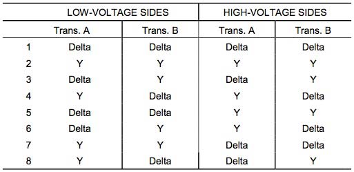 Table 1 – Operative Parallel Connections of Three-Phase Transformers
.
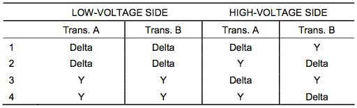 Table 2 – Inoperative Parallel Connections of Three-Phase Transformers
Wye-wye connected transformers are seldom, if ever, used to supply plant loads or as GSU units, due to the inherent third harmonic problems with this connection. Delta-delta, delta-wye, and wye-delta are used extensively at Reclamation facilities. Some rural electric associations use wye-wye connections that may be supplying reclamation structures in remote areas.
There are three methods to negate the third harmonic problems found with wye-wye connections:
- Primary and secondary neutrals can be connected together and grounded by one common grounding conductor.
- Primary and secondary neutrals can be grounded individually using two grounding conductors.
- The neutral of the primary can be connected back to the neutral of the sending transformer by using the transmission line neutral.
In making parallel connections of transformers, polarity markings must be followed. Regardless of whether transformers are additive or subtractive, connections of the terminals must be made according to the markings and according to the method of the connection (i.e., delta or wye).
CAUTION:
As mentioned above regarding paralleling single-phase units, when connecting additive polarity transformers to subtractive ones, connections will be in different locations from one transformer to the next.
.
Related articles
3,807 views

Siemens technical publication | Loss Of Vacuum
If a vacuum interrupter should lose vacuum, several operating situations should be considered:
1. With contacts open
2. When closing
3. When closed and operating normally
4. When opening and interrupting normal current
5. When opening and interrupting a fault.
Cases 1, 2 and 3 are relatively straightforward. Generally, the system sees no impact from loss of vacuum in such a situation. Cases 4 and 5, however, require further discussion. Suppose there is a feeder circuit breaker with a vacuum interrupter on phase 3 that has lost vacuum. If the load being served by the failed interrupter is a deltaconnected (ungrounded) load, a switching operation would not result in a failure. Essentially, nothing would happen. The two good phases (phase 1 and phase 2, in this example) would be able to clear the circuit, and current in the failed interrupter (phase 3) would cease.
The alternative case of a grounded load is a different situation. In this case, interruption in the two good phases (phase 1 and phase 2) would not cause current to stop flowing in phase 3, and the arc would continue to exist in phase 3. With nothing to stop it, this current would continue until some backup protection operated. The result, of course, would be destruction of the interrupter.
Since the predominant usage of circuit breakers in the 5-15 kV range is on grounded circuits, we investigated the impact of a failed interrupter some years ago in the test lab. We intentionally caused an interrupter to lose vacuum by opening the tube to the atmosphere. We then subjected the circuit breaker to a full short circuit interruption. As predicted,
the “flat” interrupter did not successfully clear the affected phase, and the “flat” interrupter was destroyed. The laboratory backup breaker cleared the fault. Following the test, the circuit breaker was removed from the switchgear cell. It was very sooty, but mechanically intact. The soot was cleaned from the circuit breaker and the switchgear cell, the faulty interrupter was replaced, and the circuit breaker was re-inserted in the cell. Further short circuit interruption tests were conducted the same day on the circuit breaker.
Field experience in the years since that test was conducted supports the information gained in the laboratory experiment. One of our customers, a large chemical operation, encountered separate failures (one with an air magnetic circuit breaker and one with a vacuum circuit breaker) on a particular circuit configuration. Two different installations, in different countries, were involved. They shared a common circuit configuration and failure mode. The circuit configuration, a tie circuit in which the sources on each side of the circuit
breaker were not in synchronism, imposed approximately double rated voltage across the contact gap, which caused the circuit breaker to fail. Since these failures resulted from application in violation of the guidelines of the ANSI standards, and greatly in excess of the design ratings of the circuit breakers, they are not indicative of a design
problem with the equipment.
However, the damage that resulted from the failures is of interest. In the case of the air magnetic circuit breaker, the unit housing the failed circuit breaker was destroyed, and the adjacent switchgear units on either side were damaged extensively, requiring significant rebuilding. The air magnetic circuit breaker was a total loss. In the case of the vacuum circuit breaker, the failure was considerably less violent. The vacuum interrupters were replaced, and the arc by-products (soot) cleaned from both the circuit breaker and the compartment. The unit was put back into service. Our test experience in the laboratory, where we routinely explore the limits of interrupter performance, also supports these results.
More recently, several tests were performed in our high-power test laboratory to compare the results of attempted interruptions with “leaky” vacuum interrupters. A small hole (approximately 1/8” diameter) was drilled in the interrupter housing, to simulate a vacuum interrupter that had lost vacuum.
The results of these tests were very interesting:
- One pole of a vacuum circuit breaker was subjected to an attempted interruption of 1310 A (rated continuous current = 1250 A). The current was allowed to flow in the “failed” interrupter for 2.06 seconds, at which point the laboratory breaker interrupted. No parts of the “failed” circuit breaker or the interrupter flew off, nor did the circuit breaker explode. The paint on the exterior of the interrupter arcing chamber peeled off. The remainder of the circuit breaker was undamaged.
. - A second pole of the same vacuum circuit breaker was subjected to an attempted interruption of 25 kA (rated interrupting current = 25 kA), for an arc-duration of 0.60 seconds, with the laboratory breaker interrupting the current at that time. The arc burned a hole in the side of the arc chamber. The circuit breaker did not explode, nor did parts of the circuit breaker fly off. Glowing particles were ejected from the hole in the arcing chamber. None of the mechanical components or other interrupters were damaged. Essentially, all damage was confined to the failed interrupter.
Our experience suggests rather strongly that the effects of a vacuum interrupter failure on the equipment are very minor, compared to the impact of failures with alternative interruption technologies. But the real question is not what the results of a failure might be, but rather, what is the likelihood of a failure? The failure rate of Siemens vacuum interrupters is so low that loss of vacuum is no longer a significant concern. In the early 1960s with early vacuum interrupters, it was a big problem. A vacuum interrupter is constructed with all connections between dissimilar materials made by brazing or welding. No organic materials are used. In the early years, many hand-production techniques were used, especially when borosilicate glass was used for the insulating envelope, as it could not tolerate high temperatures. Today, machine welding and batch induction furnace brazing are employed with extremely tight process control. The only moving part inside the interrupter is the copper contact, which is connected to the interrupter end plate with a welded stainless steel bellows. Since the bellows is welded to both the contact and the interrupter end plate, the failure rate of this moving connection is extremely low. This accounts for the
extremely high reliability of Siemens vacuum interrupters today.
In fact, the MTTF (mean time to failure) of Siemens power vacuum interrupters has now reached 24,000 years (as of October 1991). Questions raised by customers regarding loss of vacuum were legitimate concerns in the 1960s, when the use of vacuum interrupters for power applications was in its infancy. At that time, vacuum interrupters suffered from frequent leaks, and surges were a problem. There was only one firm that offered vacuum circuit breakers then, and reports suggest that they had many problems. We entered the vacuum circuit breaker market in 1974, using Allis-Chalmers’ technology and copper-bismuth contact materials. In the early 1980′s, after becoming part of the worldwide Siemens organization, we were able to convert our vacuum designs to use Siemens vacuum interrupters, which had been introduced in Europe in the mid-1970s. Thus, when we adopted the Siemens vacuum interrupters in the U.S., they already had a very well established field performance record.
The principle conceptual differences in the modern Siemens vacuum interrupters from the early 1960s designs lies in contact material and process control. Surge phenomena are more difficult to deal with when copper-bismuth contacts are used than with today’s chromecopper contacts. Similarly, leaks were harder to control with vacuum interrupters built largely by hand than with today’s units. Today, great attention is paid to process control and elimination of the human factor (variability) in manufacture. The result is that the Siemens vacuum interrupters today can be expected to have a long service life and to impose dielectric stress on load equipment that is not significantly different from the stresses associated with traditional air magnetic or oil circuit breakers.
.
Published by: SIEMENS AG
.
Related articles
15,276 views

Busbar Technical Specification
Copper busbars are normally part of a larger generation or transmission system. The continuous rating of the main components such as generators, transformers, rectifiers, etc., therefore determine the nominal current carried by the busbars but in most power systems a one to four second short-circuit current has to be accommodated.
The value of these currents is calculated from the inductive reactances of the power system components and gives rise to different maximum short-circuit currents in the various system sections.
.
Performance under Short-circuit Conditions
Busbar trunking systems to BS EN 60439-2 are designed to withstand the effects of short-circuit currents resulting from a fault at any load point in the system, e.g. at a tap off point or at the end of a feeder run.
.
Rating under Short-circuit Conditions
The withstand ability will be expressed in one or more of the following ways:
- short-time withstand rating (current and time)
- peak current withstand rating
- conditional short-circuit rating when protected by a short-circuit protective device (s.c.p.d.)
These ratings are explained in more detail:
1. Short-time Withstand Rating
This is an expression of the value of rms current that the system can withstand for a specified period of time without being adversely affected such as to prevent further service. Typically the period of time associated with a short-circuit fault current will be 1 second, however, other time periods may be applicable.
The rated value of current may be anywhere from about 10kA up to 50kA or more according to the construction and thermal rating of the system.
2. Peak Current Withstand Rating
This defines the peak current, occurring virtually instantaneously, that the system can withstand, this being the value that exerts the maximum stress on the supporting insulation.
In an A.C. system rated in terms of short-time withstand current the peak current rating must be at least equal to the peak current produced by the natural asymmetry occurring at the initiation of a fault current in an inductive circuit. This peak is dependent on the power-factor of the circuit under fault conditions and can exceed the value of the steady state fault current by a factor of up to 2.2 times.
3. Conditional Short-circuit Rating
Short-circuit protective devices (s.c.p.ds) are commonly current-limiting devices; that is they are able to respond to a fault current within the first few milliseconds and prevent the current rising to its prospective peak value. This applies to HRC fuses and many circuit breakers in the instantaneous tripping mode. Advantage is taken of these current limiting properties in the rating of busbar trunking for high prospective fault levels. The condition is that the specified s.c.p.d. (fuse or circuit breaker) is installed up stream of the trunking. Each of the ratings above takes into account the two major effects of a fault current, these being heat and electromagnetic force.
The heating effect needs to be limited to avoid damage to supporting insulation. The electromagnetic effect produces forces between the busbars which stress the supporting mechanical structure, including vibrational forces on A.C. The only way to verify the quoted ratings satisfactorily is by means of type tests to the British Standard.
.
Type Testing
Busbar trunking systems are tested in accordance with BS EN 60439-2 to establish one or more of the short circuit withstand ratings defined above. In the case of short-time rating the specified current is applied for the quoted time. A separate test may be required to establish the peak withstand current if the quoted value is not obtained during the short-time test. In the case of a conditional rating with a specified s.c.p.d. the test is conducted with the full prospective current value at the trunking feeder unit and not less than 105% rated voltage, since the s.c.p.d. (fuse or circuit breaker) will be voltage dependent in terms of let through energy.
.
Application
It is necessary for the system designer to determine the prospective fault current at every relevant point in the installation by calculation, measurement or based on information provided e.g. by the supply authority. The method for this is well established, in general terms being the source voltage divided by the circuit impedance to each point. The designer will then select protective devices at each point where a circuit change occurs e.g. between a feeder and a distribution run of a lower current rating. The device selected must operate within the limits of the busbar trunking short-circuit withstand.
The time delay settings of any circuit breaker must be within the specified short time quoted for the prospective fault current. Any s.c.p.d. used against a conditional short-circuit rating must have energy limitation not exceeding that of the quoted s.c.p.d. For preference the s.c.p.d. recommended by the trunking manufacturer should be used.
.
Voltage Drop
The requirements for voltage-drop are given in BS 7671: Regulation 525-01-02. For busbar trunking systems the method of calculating voltage drop is given in BS EN 60439-2 from which the following guidance notes have been prepared.
Voltage Drop
Figures for voltage drop for busbar trunking systems are given in the manufacturer’s literature.
The figures are expressed in volts or milli-volts per metre or 100 metres, allowing a simple calculation for a given length of run.
The figures are usually given as line-to-line voltage drop for a 3 phase balanced load.
The figures take into account resistance to joints and temperature of conductors and assume the system is fully loaded.
Standard Data
BS EN 60439-2 requires the manufacturer to provide the following data for the purposes of calculation, where necessary:
R20 the mean ohmic resistance of the system, unloaded, at 20ºC per metre per phase
X the mean reactance of the system, per metre per phase
For systems rated over 630A:
RT the mean ohmic resistance when loaded at rated current per metre per phase
Application
In general the voltage drop figures provided by the manufacturer are used directly to establish the total voltage drop on a given system; however this will give a pessimistic result in the majority of cases.
Where a more precise calculation is required (e.g. for a very long run or where the voltage level is more critical) advantage may be taken of the basic data to obtain a more exact figure.
- Resistance – the actual current is usually lower than the rated current and hence the resistance of the conductors will be lower due to the reduced operating temperature.
.
Rx = R20 [1+0.004(Tc - 20)] ohms/metre and Tc is approximately Ta + Trwhere Rx is the actual conductor resistance
Ta is the ambient temperature
Tr is the full load temperature rise in ºC (assume say 55ºC)
- Power factor – the load power factor will influence the voltage drop according to the resistance and reactance of the busbar trunking itself.
The voltage drop line-to-line ( Δv) is calculated as follows:Δv = √ 3 I (R x cos Φ + X sin Φ) volts/metre
where I is the load current
Rx is the actual conductor resistance (Ω/m)
X is the conductor reactance (Ω/m)
Cos Φ is the load power factor
sin Φ = sin (cos-1 Φ )
- Distributed Load – where the load is tapped off the busbar trunking along its length this may also be taken into account by calculating the voltage drop for each section. As a rule of thumb the full load voltage drop may be divided by 2 to give the approximate voltage drop at the end of a system with distributed load.
. - Frequency – the manufacturers data will generally give reactance (X) at 50Hz for mains supply in the UK. At any other frequency the reactance should be re-calculated.
.
Xf = x F/50
.
where Xf is the reactance at frequency F in Hz
.
Source: Siemens Barduct Busbar Specification
.
Related articles
We have updated the electrical engineering software list on our webpage Stručni programi. Two new software are added to the list: Short-Circuit Current Calculator and Group Motor Protection Guide. These software programs are intended to clearly present product data and technical information that will help the end user with design applications. Both softwares belong to Copper Bussmann.
.
Short-Circuit Current Calculator

Click to enlarge
An easy way to calculate prospective short-circuit current levels
The Cooper Bussmann Point-to-Point Short-Circuit Calculator is a simple, easy-to-use program that allows you to calculate prospective short-circuit currents with a reasonable degree of accuracy. These values can be calculated on the load side of a transformer, at the end of a run of cable or at the end of a busway. Calculations can be made for single or three phase systems.
.
Group Motor Protection Guide

Click to enlarge
A quick and easy-to-use program to help you meet group motor protection requirements
The NEC® section 430-53 allows two or more motors, and other loads, to be protected by the same overcurrent protective device when specific requirements are met. The Cooper Bussmann Group Motor Protection Guide program is a quick and easy-to-use program that will tell you if you meet the requirements of group motor protection by asking a series of questions. Once it is determined that you can use group motor protection, you must still meet the group switching requirements of NEC® section 430-112. The Cooper Bussmann Group Motor Protection Guide program will ask another series of questions to see if you meet these requirements.
Both software are available for download from our webpage Stručni programi.
.
Related articles

Short Circuit Parameters in Low Voltage AC Circuits
Low-voltage equipment standards IEC60947 and IEC60439 currently include short-circuit ratings for products and assemblies respectively, defined in terms of the ability of the equipment to operate at a level of peak current, an RMS current for a specified time and/or a level of current conditional upon a short-circuit protective device in series. In practice the correct application of the various short-circuit ratings needs to be fully understood by the circuit designer to avoid leaving a circuit or equipment with inadequate short-circuit protection. It is also useful to take full advantage of the capability of devices and systems to avoid over-engineering, with the consequent unnecessary additional cost. This guide does not concern itself with the issue of selectivity between devices in series, which must be considered separately.
Principles of Application
The Installation
In order to ensure the capability of equipment under short-circuits conditions the circuit designer must firstly have available the prospective fault level at the point of installation of each item of equipment. This is produced by a system protection study. IEC60781 provides an application guide for calculation of short-circuit currents in lowvoltage radial systems. Short-circuit parameters are defined by this guide in terms, which include the following:
- Prospective (available) short-circuit current:
The current that would flow if the short-circuit were replaced by an ideal connection of negligible impedance without any change of the supply. - Peak short-circuit current Ip
The maximum possible instantaneous value of the prospective (available) short-circuit current. - Symmetrical short-circuit breaking current Ib
The r.m.s. value of an integral cycle of the symmetrical a.c. component of the prospective (available) shortcircuit current at the instant of contact separation of the first pole of a switching device. - Steady-state short-circuit current Ik
The r.m.s. value of the short-circuit current which remains after the decay of the transient phenomena.
- unlimited
- limited by an SCPD (short-circuit protective device)
LV Assemblies (switchboard, distribution board etc.)
An assembly will have a short-circuit rating, assigned by the manufacturer, defined in terms of the maximum prospective fault level applicable at the point it is connected into the system.
This will have been determined by test and/or design calculations as specified in the assembly standard, IEC60439-1, or applicable part thereof.
The terminology to define the short-circuit rating of an assembly is given in the standard as follows:
- Rated short-time current (Icw) (of a circuit of an assembly)
Summarised as: The r.m.s value of short-time current that a circuit of an assembly can carry without damage under specified test conditions, defined in terms of a current and time e.g. 20kA, 0,2s. - Rated peak withstand current (Ipk) (of a circuit of an assembly)
Summarised as: The value of peak current that a circuit can withstand satisfactorily under specified test conditions. - Rated conditional short-circuit current (Icc) (of a circuit of an assembly)
Summarised as: The value of prospective short-circuit current that a circuit, protected by a specified shortcircuit protective device (SCPD), can withstand satisfactorily for the operating time of that device, under specified test conditions. Note: the short-circuit protective device may form an integral part of the assembly or may be a separate unit.An assembly may be assigned a value of Icc alone.
- An assembly may be assigned values of Icw and Ipk (but cannot be assigned a value of Icw or Ipk alone).
- An assembly may be assigned values of Icw, Ipk and Icc.
- An assembly may be assigned different values of Icc for different circuit protective devices and/or system voltages.
- An assembly may be assigned different values of Icw for different short-time periods e.g. 0.2s, 1s, 3 s.
Switchgear
In terms of short-circuit capability switchgear must be considered in respect of it’s function in the particular application. A switching device is considered in two respects, self-protection and use as a short-circuit protective device (SCPD) where applicable.
Switchgear – Self Protection Against Short Circuit
Two cases are considered:
- Load and overload switching alone, without any short-circuit switching capability:
In this case the switching device will be short-circuit rated on a similar basis to a circuit of an assembly (see above), with a rating of Icw and/or a conditional short-circuit rating, but will in addition have a rated short-circuit making capacity Icm. - Load, overload and short-circuit switching capability:
- Fused switchgear – in this case the short-circuit breaking function is provided by the integral fuses and the device will have a conditional short-circuit rating
- Circuit breakers – the circuit-breaker will be self-protecting up to its breaking capacity rating (see later). At fault levels above the breaking capacity rating a circuit-breaker may be capable of operating with ‘back-up’ protection by an SCPD (this is in effect a conditional rating, but the term is not generally used in this context).
Switchgear – Application as SCPD
- Fused Switchgear and Fuses as SCPD
Since the short-circuit breaking function in fused switchgear is provided by the fuses it is the fuse characteristics that are considered. These are given in IEC60269-1 as follows:- Breaking capacity of a fuselink
- value (for a.c. the r.m.s. value of the a.c. component) of prospective current that a fuselink is capable of breaking at a stated voltage under prescribed conditions. - Cut-off current
Summarised as: maximum instantaneous value reached by the current during the breaking operation of a fuselink when it operates to prevent the current reaching the prospective peak. - Operating I²t (Joule integral)
Summarised as: Integral of the square of the current over the operating time of the fuse.
Sometimes referred to as ‘energy let-through’. When expressed in A²t gives the energy dissipated per ohm and thus represents the thermal effect on the circuit.
- Breaking capacity of a fuselink
- Circuit-breakers as SCPD
- Moulded-case circuit-breakers (MCCBs) and air circuit-breakers (ACBs) are rated according to IEC60947-2 as follows
- Rated short-circuit making capacity (Icm)
Summarised as: The maximum peak prospective current that the circuit-breaker can make on to satisfactorily.
- Rated short-circuit making capacity (Icm)
- Rated short-circuit breaking capacities:
- Rated ultimate short-circuit breaking capacity (Icu)
Summarised as: The r.m.s prospective current that the circuit breaker is capable of breaking at a specified voltage under defined test conditions, which include one break and one make/break operations. - Rated service short-circuit breaking capacity (Ics)
Summarised as: The r.m.s prospective current that the circuit breaker is capable of breaking at a specified voltage under defined test conditions, which include one break and two make/break operations. The standard specifies fixed relationships to Icu of 25, 50, 75 or 100%. - Rated short-time withstand current (Icw)
Summarised as: The r.m.s value of short-time current assigned by the manufacturer based on specified test conditions. Minimum values are given in the standard.
- Rated ultimate short-circuit breaking capacity (Icu)
- Moulded-case circuit-breakers (MCCBs) and air circuit-breakers (ACBs) are rated according to IEC60947-2 as follows
A circuit-breaker can only be assigned a rated short-time withstand current Icw if it is equipped with a time-delay overcurrent release.
All circuit-breakers to IEC60947-2 will have values of Icu and Ics.
Characteristics of circuit-breakers not mandated in IEC60947-2 but having application to short-circuit protection:
- Cut-off current
The maximum instantaneous value reached by the current during the breaking operation of a circuit-breaker when it operates to prevent the current reaching the prospective peak. - Operating I²t (Joule integral)
Integral of the square of the current over the operating time of the circuit-breaker on a short-circuit. Sometimes referred to as ‘energy let-through’. When expressed in A²t gives the energy dissipated per ohm and thus represents the thermal effect on the circuit.
Examples of the Practical Application of the Product Characteristics
In simple studies only the r.m.s value of steady-state short-circuit current (Ik) is quoted. The peak current is assumed to be in a standard relationship to the r.m.s current, determined by the overall power factor, and taken into account in the rating of SCPDs to the respective IEC standards.
Circuit Protection
The application of short-circuit protective devices (SCPD) to circuit protection i.e. the protection of cables, is detailed in the installation rules, IEC364. In general it is accepted that selection of the protective device on the basis of thermal protection of a cable automatically provides short-circuit protection up to the breaking capacity of the SCPD, in the case of non-time-delayed devices.
Short-Circuit Protection for LV assemblies
Switchboard/Motor-Control Centre
The prospective short-circuit current at the input to the switchboard is obtained from a system protection study.
This will be given as an r.m.s value.
- If the switchboard has an Icw current value higher than the prospective current level then the only requirement is to limit the time for which a short-circuit could persist to within the short-time value. This is achieved by the setting of releases upstream or at the incomer to the switchboard.
- If the switchboard has an Icc rating higher than the prospective current level then the only requirement is to include the specified SCPD in the circuit. This may be added in the circuit upstream or may already be included as an incomer to the switchboard.
Busbar Trunking (BBT)
The prospective short-circuit current at the input to the switchboard is obtained from a system protection study.
This will be given as an r.m.s value.
- If the BBT has an Icw current value higher than the prospective short circuit current level then the only requirement is to limit the time for which a short-circuit could persist to within the short-time value. This is achieved by the time-delay setting of overcurrent releases upstream.
- If the BBT has an Icw lower than the prospective short circuit current level Ik but has an Icc rating higher than Ik then the only requirement is to include the specified SCPD in the circuit upstream or in the end-feed unit. The suitability of any given SCPD may be derived from the cut-off current and Joule-integral characteristics by comparison with proof-test parameters.
Motor Control Gear (MCG)
Motor starters and contactors are not generally self-protecting against the effects of short-circuit and therefore need to be associated with an SCPD. In this particular case test procedures to IEC60947-4-1 recognise the difficulty of protecting sensitive devices from damage under heavy short-circuit conditions. Thus a special case of conditional rating is obtained which allows two classes of co-ordination with an SCPD:
Type 1 – in which a certain amount of damage to the MCG is accepted.
Type 2 – in which the MCG is capable of further use.
These ratings can only be obtained by type-testing and thus the data must be obtained from the manufacturer of the SCPD or the MCG.
Miniature Circuit Breakers (MCBs)
When applied in other than domestic (household) situations the short-circuit capability of MCBs to IEC60898 is often inadequate and they need to be ‘backed-up’ by another SCPD. Details of how the appropriate SCPD is determined are given, for circuit-breakers, in Appendix A of IEC60947-2. Basically this shows that only testing of the required combination is satisfactory and thus the data must be obtained from the manufacturer of the SCPD or the MCB. The same applies to fuses used as SCPD.
Izvor: www.voltimum.co.uk
.
Related articles
3,064 views
Book with graphical explanations of short circuit and its calculations (purpose, standards, types, calculations…)
.


