
10,010 views

International Standard - IEC 61850
The traditional approach to substation integration used standardized RTU protocols that were designed to provide protocol efficiency for operation over bandwidth limited serial links.
While such limitations remain for many applications, substation hardened equipment implementing modern networking standards like Ethernet now provide a cost effective means of enabling high speed communications within the substation.
To truly take advantage of this technology and dramatically lower the total cost of ownership of substation automation systems, a new approach to substation integration that goes beyond a simple RTU protocol is needed.
The recent international standard IEC 61850 proposes a unified solution of the communication aspect of substation automation. However, the standard itself is not easily understood by users other than domain experts. We present our understanding of the IEC 61850 standard as well as the design and implementation of our simulation tool in this report. Also, we give suggestions on the implementation of this standard based on our experience and lessons in the development of our simulation.
1. Introduction
Today, power substations are mostly managed by substation automation systems. These systems employ computers and domain specific applications to optimize the management of substation equipment and to enhance operation and maintenance efficiencies with minimal human intervention [8].
Once upon a time, substation automation systems utilized simple, straightforward and highly specialized communication protocols [7]. These protocols concerned less about the semantics of the exchanged data, data types of which were relatively primitive. Equipment was dumb and systems were simple. However, today’s substation automation systems can no longer enjoy such simplicity because of their growing complexity — equipment becomes more intelligent and most of those simple old systems have been gradually replaced by open systems, which embrace the advantage of emerging technology like relational database systems, multi-task operating systems and support for state-of-the-art graphical display technology.
Besides, devices from different manufacturers used different substation automation protocols [9, 3, 12], disabling them to talk to each other. Utilities have been paying enormous money and time to configure these devices to work together in a single substation. Today most utilities and device manufacturers have recognized the need for a unified international standard to support seamless cooperation among products from different vendors.
The IEC 61850 international standard, drafted by substation automation domain experts from 22 countries, seeks to tackle the aforementioned situation. This standard takes advantage of a comprehensive object-oriented data model and the Ethernet technology, bringing in great reduction of the configuration and maintenance cost. Unlike its predecessor, the Utility Communication Architecture protocol 2.0 (UCA 2.0) [12], the IEC 61850 standard is designed to be capable for domains besides substation automation. To make the new protocol less domain dependent, the standard committee endeavored to emphasize on the data semantics, carving out most of the communication details. This effort, however, could result in difficulties in understanding the standard.
In this research project, we aim to get a clear understanding of the IEC 61850 standard and simulate the protocol based on J-Sim [11]. Our ultimate goal is to investigate the security aspect about the IEC 61850 standard.
2 The IEC 61850 standard
The first release of the IEC 61850 consists of a set of documents of over 1,400 pages. These documents are divided into 10 parts, as listed in Table 1. Part 1 to Part 3 give some general ideas about the standard. Part 4 defines the project and management requirements in an IEC 61850 enabled substation. Part 5 specifies the required parameters for physical implementation. Part 6 defines an XML based language for IED configuration, presenting a formal view of the concepts in the standard. Part 7 elaborates on the logical concepts, which is further divided into four subparts (listed in Table 2). Part 8 talks about how to map the internal objects to the presentation layer and to the Ethernet link layer. Part 9 defines the mapping from sampled measurement value (SMV) to point-to-point Ethernet.
The last part gives instructions on conformance testing. Since Part 7 defines the core concepts of the IEC 61850 standard, we will focus on this part in this report.
| Subpart | Title |
| 7.1 | .Principles and Models |
| 7.2 | .Abstract Communication Service Interface |
| 7.3 | .Common Data Classes |
| 7.4 | .Compatible Logical Node Classes and Data Classes |
| Table 2: Subparts of IEC 61850-7 | |
The IEC 61850 standard is not easy to understand for people other than experts in the substation automation domain due to the complexity of the documents and the assumed domain-specific knowledge. Introductory documents on the standard abound [13, 4, 7, 5, 8, 2], but most of them are in the view of substation automation domain experts. Kostic et al. explained the difficulties they had in understanding the IEC 61850 standard [7].
In this section, we provide another experience of understanding this standard, trying to explain the major concepts of the IEC 61850 standard.
2.1 Challenges
Understanding the IEC 61850 standard proposes the following challenges for a outsider of the substation automation domain:
- As a substation automation standard proposed by a group of domain experts, the IEC 61850 protocol assumes quite an amount of domain-specific knowledge, which is hardly accessible by engineers and researchers out of the substation automation domain. To make things worse, the terms used in the standard is to some extent different from those commonly used in software engineering, bringing some difficulties for software engineers in reading the standard.
- The entire standard, except Part 6, is described in natural language with tables and pictures, which is known to be ambiguous and lack of preciseness. This situation is problematic because the IEC 61850 concepts are defined by more than 150 mutually relevant tables distributed over more than 1,000 pages. A formal presentation of all these concepts would be appreciated.
- The experts proposing this protocol come from 22 different countries and are divided into 10 working groups, each responsible to one part of the standard. Due to the different backgrounds and the informal presentation style of the standard, the standard contains a considerable number of inconsistencies. Such inconsistencies are more obvious for different parts of the standard, e.g. the data model described in Part 6 is clearly different from that described in Part 7.
- The standard committee made a great effort to describe the protocol in an object-oriented manner but the result is not so object-oriented. For example, the ACSI services are grouped by different classes, but reference to the callee object is not defined as a mandatory argument of the service function.
- The standard is designed to be implementation independent but this is not always true. For example, the data attribute TimeAccuracy in Part 7-2 Table 8 is defined as CODED ENUM, while what it virtually represents is a 5-bit unsigned integer; the frequent use of PACKED LIST (i.e. “bit fields” in the C language) also brings implementation details to interface design.
- Things are mixed up in the documents. Mandatory components and optional components are mixed in the standard, and domain independent concepts are mixed up with domain specific concepts. Even though the optional components and mandatory ones are marked with “O” and “M” alternatively, it would be a tough task to refine a model consisting only the mandatory components due to the implicit dependences between attributes in different tables and the conditional inclusion of some attributes. In fact, there are 29 common data classes and 89 compatible logical nodes defined in the standard, the relationship among which is unclear.
.
2.2 Intelligent electronic device
In the past, utility communication standards usually assumed some domain-specific background of the readers. Consequently, they contained a lot of implicit domain knowledge, which is hardly accessible to outsiders (e.g. software engineers) [7]. The IEC 61850 standard does not escape from this category. To help understanding the logical concepts of IEC 61850, we would like to lay a basic idea of intelligent electronic devices (IED), the essential physical object hosting all the logical objects.
Basically, the term intelligent electronic device refers to microprocessor-based controllers of power system equipment, which is capable to receive or send data/control from or to an external source [8]. An IED is usually equipped with one or more microprocessors, memory, possibly a hard disk and a collection of communication interfaces (e.g. USB ports, serial ports, Ethernet interfaces), which implies that it is essentially a computer as those for everyday use.
However, IEDs may contain some specific digital logics for domain-specific processing.
IEDs can be classified by their functions. Common types of IEDs include relay devices, circuit breaker controllers, recloser controllers, voltage regulators etc.. It should be noted that one IED can perform more than one functions, taking advantage of its general-purpose microprocessors. An IED may have an operating system like Linux running in it.
| Part | Title |
| 1 | .Introduction and Overview |
| 2 | .Glossary |
| 3 | .General Requirements |
| 4 | .System and Project Management |
| 5 | .Communication Requirements for Functions and Device .Models |
| 6 | .Configuration Description Language for Communication in .Electronic Substations Related to IEDs |
| 7 | .Basic Communication Structure for Substation and Feeder .Equipment |
| 8 | .Specific Communication Service Mapping (to MMS and to .Ethernet) |
| 9 | .Specific Communication Service Mapping (from Sampled .Values) |
| 10 | .Conformance Testing |
| Table 1: Parts of the IEC 61850 standard documents | |
2.3 Substation architecture
A typical substation architecture is shown in Figure 1. The substation network is connected to the outside wide area network via a secure gateway. Outside remote operators and control centers can use the abstract communication service interface (ACSI) defined in Part 7-2 to query and control devices in the substation. There is one or more substation buses connecting all the IEDs inside a substation. A substation bus is realized as a medium bandwidth Ethernet network, which carries all ACSI requests/responses and generic substation events messages (GSE, including GOOSE and GSSE).
There is another kind of bus called process bus for communication inside each bay. A process bus connects the IEDs to the traditional dumb devices (merge units, etc.) and is realized as a high bandwidth Ethernet network. A substation usually has only one global substation bus but multiple process buses, one for each bay.

Figure 1: Substation architecture
ACSI requests/responses, GSE messges and sampled analog values are the three major kinds of data active in the substation network. Since we are less interested in communication on the process buses (like sampled value multicasting), we focus on the activities on the substation bus in this report, especially the ACSI activities.
Interactions inside a substation automation system mainly fall into three categories: data gathering/setting, data monitoring/reporting and event logging.
The former two kinds of interactions are the most important — in the IEC 61850 standard all inquiries and control activities towards physical devices are modeled as getting or setting the values of the corresponding data attributes, while data monitoring/reporting provides an efficient way to track the system status, so that control commands can be issued in a timely manner.
To realize the above kinds of interaction, the IEC 61850 standard defines a relatively complicated communication structure, as is shown in Figure 2.

Figure 2: The communication profiles
Five kinds of communication profiles are defined in the standard: the abstract communication service interface profile (ACSI), the generic object oriented substation event profile (GOOSE), the generic substation status event profile (GSSE), the sampled measured value multicast profile (SMV), and the time synchronization profile. ACSI services enable client-server style interaction between applications and servers.
GOOSE provides a fast way of data exchange on the substation bus and GSSE provides an express way of substation level status exchange. Sample measured value multicast provides an effective way to exchange data on a process bus.
.
2.4 Abstract communication service interface
ACSI is the primary interface in the IEC 61850 standard not only because it is the interface via which applications talk with servers, but also in the sense that the ACSI communication channel is an important part of a logical connection between two logical nodes. ACSI defines the semantics of the data exchanged between applications and servers, thus it becomes the major part of the IEC 61850 standard.
The standard committee adopt an object-oriented approach in the design of ACSI, which includes a hierarchical and comprehensive data model and a set of available services for each class in this data model. Although the data model is usually described outside the scope of the ACSI, it is actually part of it. The benefits of using an object-oriented utility communication interface are two fold. On the one hand, objects (e.g. registers) can be referenced in an intuitive way (e.g. “Relay0/MMXU0.voltage”) instead of by the traditional physical address (like Reg#02432). On the other hand, software engineers can build more reliable applications using such service interface.
In the following two sections, we present a brief description on these two ACSI components.
.
2.5 Data model
The hierarchical data model defined in the IEC 61850 is depicted in Figure 3 and Figure 4.
Server is the topmost component in this hierarchy. It serves as the joint point of physical devices and logical objects. Theoretically one IED may host one or more server instances, but in practice usually only one server instance runs in an IED. A server instance is basically a program running in an IED, which shares the same meaning with other servers like FTP server etc.. Each server has one or more access points, which are the logical representation of a NIC. When a client is to access data or service of the server, it should connect to an access point of this server and establish a valid association.
Each server hosts several files or logical devices. Clients can manipulate files in the server like talking to a FTP server, which is usually used as a means to upload/update the configuration file of an IED. A logical device is the logical correspondence of a physical device. It is basically a group of logical nodes performing similar functions.
Functions supported by an IED are conceptually represented by a collection of primitive, atomic functional building blocks called logical nodes.
The IEC 61850 standard predefines a collection of template logical nodes (i.e. compatible logical nodes) in Part 7-4. Besides the regular logical nodes for functions, the standard also requires every logical device have two specific logical nodes: Logical Node Zero (LN0) and LPHD, which correspond to the logical device and the physical device, alternatively. Besides holding status information of the logical device, LN0 also provides additional functions like setting-group control, GSE control, sampled value control etc..
In the IEC 61850 standard, the entire substation system is modeled as a distributed system consisting of a collection of interacting logical nodes, which are logically connected by logical connections. It should be noted that the term logical connection refers to the logical concept of the connections between two logical nodes, which can be direct or indirect or even a combination of many different kinds of communication channels. In fact, the connection of two logical nodes is usually both indirect and a combination of TCP, UDP and direct Ethernet connections. We will explain logical connections in Section 2.9 (next article).
Data exchanged between logical nodes are modeled as data objects. A logical node usually contains several data objects. Each data object is an instance of the DATA class and has a common data class type.

Figure 3: Hierarchy of the IEC 61850 data model
Similar to the concept of objects in most object-oriented programming languages, a data object consists of many data attributes, which are instances of data attributes of the corresponding common data class. Data attributes are typed and restricted by some functional constraints. Instead of grouping data attributes by data objects, functional constraints provide a way to organize all the data attributes in a logical node by functions. Types of data attributes can be either basic or composite.
Basic types are primitive types in many programming languages, whereas composite types are composition of a collection of primitive types or composite types.
In the IEC 61850 standard, data attributes are at least as important as, if not more than, data objects for two reasons.

Figure 4: The data model of the IEC 61850
Firstly, data objects are just logical collections of the contained data attributes while (primitive) data attributes are the de facto logical correspondence to the physical entities (memory units, registers, communication ports, etc.); secondly, the purpose of data objects is for the convenience of managing and exchanging values of a group of data attributes sharing the same function.
Despite data objects, the IEC 61850 standard provides the concept of data set as another ways to manage and exchange a group of data attributes. Members of a data set can be data objects or data attributes. The concept of data set is somewhat similar to the concept of view in the area of database management systems.
In the IEC 61850 standard, most services involve data sets. Members in a data set unnecessarily come from the same logical node or the same data object, thus providing high flexibility of data management. Data sets are categorized into permanent ones and temporary ones.
Permanent data sets are hosted by logical nodes and will not be automatically deleted unless on the owners’ explicit requests; temporary data sets are exclusively hosted by the association having created them and will be automatically deleted when the association ends.
To be continued soon in next article: IEC 61850 in details (2)
SOURCE:
- Understanding and Simulating the IEC 61850 Standard by Yingyi Liang & Roy H. Campbell, Department of Computer Science University of Illinois at Urbana-Champaign
.
Related articles
- IEC 61850 Standard In Details (2)
- Benefits Of IEC 61850
- Testing performances of IEC 61850 GOOSE messages
- Testiranje performansi IEC 61850 GOOSE poruka
- The New ETS4: Easy, Fast, Open
6,457 views

Maintenance Of Low Voltage Circuit Breakers
The deterioration of low voltage circuit breaker is normal and this process begins as soon as the circuit breaker is installed. If deterioration is not checked, it can cause failures and malfunctions. The purpose of an electrical preventive maintenance and testing program should be to recognize these factors and provide means for correcting them.
A good organized maintenance program can minimize accidents, reduce unplanned shutdowns and lenghten the mean time between failures of electrical equipment.
Benefits of good electrical equipment maintenance can be reduced cost of process shutdown (caused by circuit breaker failure), reduced cost of repairs, reduced downtime of equipment, improved safety of personnel and property.
Frequency Of Maintenance
Low-voltage circuit breakers operating at 600 volts alternating current and below should be inspected and maintained very 1 to 3 years, depending on their service and operating conditions. Conditions that make frequency maintenance and inspection necessary are:
- High humidity and high ambient temperature.
- Dusty or dirty atmosphere.
- Corrosive atmosphere.
- Frequent switching operations.
- Frequent fault operations.
- Older equipment.
A breaker should be inspected and maintained if necessary whenever it has interrupted current at or near its rated capacity.
Maintenance Procedures
Manufacturer’s instructions for each cir cuit breaker should be carefully read and followed. The following are general pro cedures that should be followed in the maintenance of low-voltage air circuit breakers:
- An initial check of the breaker should be made in the TEST position prior to withdrawing it from to enclosure.
- Insulating parts, including bushings, should be wiped clean of dust and smoke.
- The alignment and condition of the movable and stationary contacts should be checked and adjusted according to the manufacturer’s instruction book.
- Check arc chutes and replaces any damaged parts.
- Inspect breaker operating mechanism for loose hardware and missing or broken cotter pins, etc. Examine cam, latch, and roller surfaces for damage or wear.
- Clean and relubricate operating mechanism with a light machine oil (SAE-20 or 30) for pins and bearings and with a nonhardening grease for the wearing surfaces of cams, rollers, etc.
- Set breaker operating mechanism adjustments as described in the manufacturer’s instruction book. If these adjustments cannot be made within the specified tolerances, it may indicate excessive wear and the need for a complete overhaul.
- Replace contacts if badly worn or burned and check control device for freedom of operation.
- Inspect wiring connections for tightness.
- Check after servicing circuit breaker to verify the contacts move to the fully opened and fully closed positions, that there is an absence of friction or binding, and that electrical operation is functional.
Much of the essence of effective electrical equipment preventive maintenance can be sumarrized by four rules:
- Keep it DRY
- Keep it CLEAN
- Keep it COOL
- Keep it TIGHT
SOURCES:
- MAINTENANCE OF POWER CIRCUIT BREAKERS by HYDROELECTRIC RESEARCH AND TECHNICAL SERVICES GROUP
- ELECTRICAL POWER EQUIPMENT MAINTENANCE AND TESTING – By Paul Gill
.
Related articles
- Maintenance Of Meduim Voltage Circuit Breakers
- GE AKD-20 Low-Voltage Switchgear
- Maintenance Of SF6 Gas Circuit Breakers
- Siemens MV Topic – Loss Of Vacuum
- Maintenance Of High Voltage Circuit Breakers
")
Maintenance Of Molded Case Circuit Breakers (MCCB)
The maintenance of circuit breakers deserves special consideration because of their importance for routine switching and for protection of other equipment.
Electric transmission system breakups and equipment destruction can occur if a circuit breaker fails to operate because of a lack of preventive maintenance.
The need for maintenance of circuit breakers is often not obvious as circuit breakers may remain idle, either open or closed, for long periods of time. Breakers that remain idle for 6 months or more should be made to open and close several times in succession to verify proper operation and remove any accumulation of dust or foreign material on moving parts and contacts.
Frequency Of Maintenance
Molded case circuit breakers are designed to require little or no routine maintenance throughout their normal life time. Therefore, the need for preventive maintenance will vary depending on operating conditions. As an accumulation of dust on the latch surfaces may affect the operation of the breaker, molded case circuit breakers should be exercised at least once per year.
Routine trip testing should be performed every 3 to 5 years.
Routine Maintenance Tests
Routine maintenance tests enable personnel to determine if breakers are able to perform their basic circuit protective functions. The following tests may be performed during routine maintenance and are aimed at assuring that the breakers are functionally operable. The following tests are to be made only on breakers and equipment that are deenergized.
Insulation Resistance Test
A megohmmeter may be used to make tests between phases of opposite polarity and from current-carrying parts of the circuit breaker to ground. A test should also be made between the line and load terminals with the breaker in the open position. Load and line conductors should be dis connected from the breaker under insulation resistance tests to prevent test mesurements from also showing resistance of the attached circuit.
Resistance values below 1 megohm are considered unsafe and the breaker should be inspected for pos sible contamination on its surfaces.
Milivolt Drop Test
A millivolt drop test can disclose several abnor mal conditions inside a breaker such as eroded contacts, contaminated contacts, or loose internal connec tions. The millivolt drop test should be made at a nominal direct-current volt age at 50 amperes or 100 amperes for large breakers, and at or below rating for smaller breakers. The millivolt drop is compared against manufacturer’s data for the breaker being tested.
Connections Test
The connections to the circuit breaker should be inspected to determine that a good joint is present and that overheating is not occurring. If overheating is indi cated by discoloration or signs of arcing, the connections should be re moved and the connecting surfaces cleaned.
Overload tripping test
The proper action of the overload tripping components of the circuit breaker can be verified by applying 300 percent of the breaker rated continuous current to each pole. The significant part of this test is the automatic opening of the circuit breaker and not tripping times as these can be greatly affected by ambient conditions and test condi tions.
Mechanical operation
The mechanical operation of the breaker should be checked by turning the breaker on and off several times.
SOURCE: HYDROELECTRIC RESEARCH AND TECHNICAL SERVICES GROUP
.
Related articles
- Line Protection With Distance Relays
- UPS design criteria and selection
- Current Switching with High Voltage Air Disconnector
- Standard IEC 60947-2
- Maintenance Of SF6 Gas Circuit Breakers
16,595 views

Caterpillar C175 Diesel Generator 2-4MW
The C175 family of diesel generator sets offers the most power you can get in any single high-speed package: 2-4MW.
One of the most significant components in the development of the C175 was the integration of ACERT™ Technology into the engine platform.
ACERT Technology is a synergistic approach utilizing a suite of complementary building block technologies that can be individually adapted to accommodate a specific application. In recent years, Caterpillar has spent more than $1 billion on the development of clean diesel technologies. Today, more than 330,000 engines are currently in operation with ACERT Technology, accumulating more than 2 million hours of use each day.
With the C175, the building blocks of ACERT Technology have been tailored to meet the current and pending emissions requirements of stationary diesel generator sets in a variety of applications.
Advantages
Thousands of hours of customer research created the foundation for the C175 design concept.
Some of the major advantages of the C175 family include:
- Proven Reliability with platform based on industry standard Cat® 3500 series, and supported by thousands of hours of lab and field-testing.
- Wider Power Range including 2000kW to 4000kW @ 1500 and 1800 rpm.
- Power Generation at Higher Speed than traditional medium speed products in the same power range.
- Higher Power Density equals more output from a given engine displacement / footprint, resulting in lower installed cost.
- Complete Package including SR5 generators, EMCP3 package controls and package/remote radiator with flexible controls packaging options simplifies installation.
- Lower Emissions meet U.S. EPA Tier 2 standards with a line of sight to meet U.S. EPA Tier 4 and EU Stage IIIB emissions levels.
- Lower Maintenance Costs due to increased oil change intervals, longer life (durability) of components and longer top end as well as full overhaul periods.
- Lower Operating Costs due to lower brake specific fuel consumption than competitive products.
- Systems Integration. The C175 electrical system components are engineered to work together with a wide range of products such as Uninterruptible Power Supplies (UPS), Automatic Transfer Switches (ATS), switchgear, remote monitoring services and customer building SCADA systems.
- Extensive Product Support from a worldwide dealer network with 24/7/365 parts and service availability.
Design Features
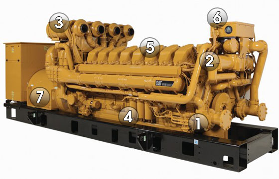
1. Fuel System

C175 - Fuel System
The new C175 engine features a Cat® Common Rail Fuel System designed specifically for this engine platform.
Full Control of Both Fuel Delivery and Fuel Pressure At Any Load or Speed results in superior transient response and block load acceptance, as well as shorter recovery time.
More Compact single camshaft that is used only to open the intake and exhaust valves. It features a simpler injection design with no pumping function necessary.
Improved Cold Start Capability uses higher pressures at low speeds and produces less smoke.
“Fluid Containment” Design. The high-pressure lines and rails are designed to provide outer concentric low-pressure containment. If a leak occurs in the high-pressure section, it leaks back to the outer low-pressure section and drains back to the tank.
Integrated Manifold or Monoblock offers a single point of connection to the engine, which eliminates leak paths while improving reliability.
Fuel Cooler Eliminated. Unlike the unit injector system, the Common Rail System used on the C175 does not require excess bypass fuel to cool the injector since injection pressure load is taken off the injector. The result is a reduction of heat generation in the return fuel and reduction in fuel flow rate by a factor of 4 when compared to the unit injector system. This eliminates the need for a fuel cooler in most cases.
Improved Fuel Filters. The C175 uses an eco-friendly fuel filter system. Instead of throwing away the whole canister, only the disposable non-metallic element inside the canister is changed.
Electronic Fuel Priming Pump is Engine Control Module (ECM)-controlled and offered as standard equipment. No manual effort is required to pump the fuel, so it’s more convenient and requires less operator effort.
2. Cooling System

C175 - Cooling System
The design philosophy for the Cat® C175 cooling system is to minimize heat rejection by cooling only the parts that require cooling.
Inlet-Regulated System. The C175 features an innovative design unique to Caterpillar. The system senses the temperature at the inlet and controls the output providing more consistent temperatures and better control of oil viscosity than an outlet-regulated system.
Electronic Fluid Temperature Controller regulates inlet temperature of the coolant and allows for troubleshooting without removing the thermostat. Improved diagnostics enable the operator to pinpoint a problem quickly, which increases reliability and uptime.
Integral Water Supply and Return Manifold are built into the engine block to minimize connection points and bolted joints. This design helps contain fluids and improves overall engine reliability and serviceability.
Two-Stage After-Cooler. The first stage is cooled by a jacket water circuit and the second stage has a two-pass separate circuit. The after-cooler is constructed with tube fin cores that are more robust compared to the traditional bar plate fin design. The tubes of the core can be cleaned without removing the core from the engine, and the core can be remanufactured. The tubes also have more surface area per volume and less pressure drop, resulting in more efficient cooling. This after-cooler design also minimizes the size of the SCAC circuit, thereby reducing the size of the radiator. The location of the first stage jacket water core provides protection from high air temperatures. These features improve the durability and reliability of the cooling system.
3. Air Management

C175 - Air Management
Air management is one of the ACERT™ Technology building blocks used on the Cat® C175 engine.
Crossflow Head provides separation between both the intake and exhaust ports and manifolds. The outboard air manifold location eliminates re-heating of intake air by preventing heat transfer from the exhaust to the intake. This results in reduced charge air temperature and increased charge air density, enabling higher power density as well as reducing SCAC cooling.
Taller Head accommodates larger ports and helps direct a large amount of cool air into the cylinder with the least resistance, resulting in the best port performance of any engine in the world. The taller head also accommodates increased valve lift of 22mm compared to 18mm on the Cat 3500, further improving breathing.
Improved Breathing. The tall crossflow head results in a greater amount of cooler air in and out of the engine, which helps produce higher power ratings and lower emissions. This, along with lower air pumping losses, results in lower fuel consumption.
New Generation of Turbochargers designed specifically for the C175. Four single-stage turbochargers provide a higher pressure ratio in a single stage. The turbocharger includes a cast titanium impeller and an improved bearing system that provides a higher load-bearing capacity and greater reliability, while increasing efficiency by 5% and extending the component life when compared to traditional cast aluminum impellers.
4. Lube System

C175 - Lube Management
The C175 lube system features two piston-cooling jets per piston.
A large capacity oil pump pressure regulation valve allows the engine to maintain optimum oil pressure at all speeds, loads and throughout the life of the engine, ultimately increasing durability.
.
.
.
5. Core Engine Components

C175 - Core Engine Components
The components of the new C175 centerline engine are designed for higher strength, durability and compactness.
Crankshaft has a larger diameter to handle bigger loads. It is made of steel forged material and features induction hardened fillets and journals. Thrust plates are located at the rear end of the crankshaft to reduce motion inside of the coupling between the engine and generator.
Block is made of cast iron and provides increased strength and stiffness, and is lighter weight.
Mid-Support Liners provide stronger support to the liner and offer more efficient cooling by only cooling the top 25% of the cylinder liner. Mid-support liners allow for a smaller inside diameter of the combustion seal, as well as a higher position for the piston’s top ring. The result is reduced crevice volume, improved cooling and combustion efficiency, and reduced emissions. Mid-support liners allow the head bolts to be closer to the cylinder bore to minimize cylinder spacing and to create a more compact engine.
Cylinder Cuff is specially designed for improved durability. The ring of the “cuff” located at the top of the cylinder scrapes off carbon accumulation on the piston top end, preventing the carbon from polishing, scratching or seizing the liner. The cuff also helps reduce crevice volume beside the piston, resulting in lower emissions.
Cylinder Head is made of iron for added strength. The tall C175 head helps eliminate the external water manifold by returning the coolant to the cylinder block.
Head Gasket features a simplified two-piece (carrier seal and combustion seal) design, shortening service time, decreasing parts costs, and increasing reliability and durability.
Pistons and Rings feature increased oil flow to pistons for better cooling and higher power ratings. Rectangular piston rings provide a superior seal and less motion, resulting in less wear and longer life. Piston, rod and liner come out as one assembly, resulting in faster, easier service.
Connecting Rods. Large diameter fracture split connecting rods provide better alignment between the rod and cap, which eliminates the need for a special alignment procedure.
Bearings. Large main and rod bearings provide better seizure resistance and better tolerance of a wide range of oil temperatures. Larger rod bearing and main bearing are more scuff and seizure resistant.
6. Engine Management System

C175 - Engine Management System
The Cat® C175 utilizes much of the ACERT™ Technology electronics experience gained on small-bore engines and employs many new improvements and technologies more useful on large bore engines. The C175 Engine Management System exploits the power of modern control technology to improve reliability, exceed customer expectations and accommodate future customer requirements.
Engine Control Module (ECM). C175 engine controls use the latest version of the ADEM™ A4 ECM to deliver 50 times the computing power of its predecessor. Specific benefits include monitoring over 30 points on the engine, driving up to 20 injectors, protecting the engine, communicating over 100 engine parameters to the customer, diagnosing and reporting on engine health. The ECM uses the latest advancements in ACERT Technology to improve engine performance while reducing emissions.
Engine Controls and Datalink. Three primary controllers are temperature control module, fuel high-pressure controller and ECM. These are connected to the engine J1939 datalink.
Rigid Wiring Harness. Metal enclosed rigid wiring harness system protects critical engine circuits from accidental damage, reducing service calls and increasing reliability.
Controls Packaging. The standard panel is a rear-mounted EMCP 3.1 with the option to upgrade to the EMCP 3.2 or EMCP 3.3.
7. Generator

C175 - Generator
Caterpillar is introducing the next evolution of generators, the SR5 Series, with the introduction of the C175 generator sets. The SR5 Series 1800 and 3000 frame generators have been designed specifically to work with the C175 engines. The structural design is matched to the C175 engine. Torsional and linear vibration analysis and testing have been performed to ensure durability.
The SR5 generator’s insulation system has been improved to meet insulation Class H. SR5 generators feature 2/3-pitch as standard on all low, medium and high voltage generators. SR5 generators have IP23 particle ingress protection.
Generator Set Packaging. The C175 uses a fusible coupling to connect the generator to the engine. All engines, generators and controls are tested individually prior to assembly. Once assembled, the entire generator set package is tested before shipping to dealers to ensure quality.
Applications
The versatility of the C175 makes it ideal for a variety of applications.
- Continuous – A continuous rating has a typical load factor of 70% to 100% with no limit on the number of hours per year. Typical peak demand is 100% of continuous rated kW for 100% of operating hours. Typical applications include base load, utility or co-generation.
- Prime – A prime rating has a typical load factor of 60% to 70% with no limit on the number of hours per year. Typical peak demand is 100% of prime rated kW with 10% overload available for emergency use for up to one hour in 12. Typical applications include industrial, pumping, construction, peak shaving or co-generation.
- Standby – A standby rating has a typical load factor of 70% or less with variable load for about 200 hours per year,with a maximum expected usage of 500 hours per year. Typical peak demand is 80% of the standby rated kW with power available for the duration of an emergency outage. Typical applications include building service standby or emergency standby.
- Load Management – A load management rating has a typical load factor of 100% of the prime rating for a maximum of 500 hours per year. Typical peak demand is 100% of the load management rating, with no overload available. Typical applications include base load or peak shaving.
SOURCE: Caterpillar C175
.
Related articles
- Transformer Ratings
- Bus Joint Fundamentals
- Hydropower – Systems Overview (2)
- Transformer heating and cooling
- Comparison Between Vacuum and SF6 Circuit Breaker
7,141 views

Lighting Fundamentals
Illuminance is light falling on a surface measured in footcandles or lux. Distributed with an economic and visual plan, it becomes engineered lighting and, therefore, practical illumination.
A lighting designer has four major objectives:
1. Provide the visibility required based on the task to be performed and the economic objectives.
2. Furnish high quality lighting by providing a uniform illuminance level, where required, and by minimizing the negative effects of direct and reflected glare.
3. Choose luminaires aesthetically complimentary to the installation with mechanical, electrical and maintenance characteristics designed to minimize operational expense.
4. Minimize energy usage while achieving the visibility, quality and aesthetic objectives.
CONTENTS
.
1. ILLUMINATION
| 1.1 | Quantity of Illumination | |
| 1.2 | Quality of Illumination |
.
.
1.1 Quantity of Illumination
Light Output

Light Output - Light Level - Brightness
The most common measure of light output (or luminous flux) is the lumen. Light sources are labeled with an output rating in lumens.
For example, a T12 40-watt fluorescent lamp may have a rating of 3050 lumens. Similarly, a light fixture’s output can be expressed in lumens. As lamps and fixtures age and become dirty, their lumen output decreases (i.e., lumen depreciation occurs).
Most lamp ratings are based on initial lumens (i.e., when the lamp is new).
.
Light Level
Light intensity measured on a plane at a specific location is called illuminance. Illuminance is measured in footcandles, which are workplane lumens per square foot. You can measure illuminance using a light meter located on the work surface where tasks are performed. Using simple arithmetic and manufacturers’ photometric data, you can predict illuminance for a defined space. (Lux is the metric unit for illuminance, measured in lumens per square meter. To convert footcandles to lux, multiply footcandles by 10.76.)
Brightness
Another measurement of light is luminance, sometimes called brightness. This measures light “leaving” a surface in a particular direction, and considers the illuminance on the surface and the reflectance of the surface.
The human eye does not see illuminance; it sees luminance. Therefore, the amount of light delivered into the space and the reflectance of the surfaces in the space affects your ability to see.
Quantity Measures
- Luminous flux is commonly called light output and is measured in lumens (lm).
- Illuminance is called light level and is measured in footcandles (fc).
- Luminance is referred to as brightness and is measured in footlamberts (fL) or candelas/m2 (cd/m2).
Determining Target Light Levels
The Illuminating Engineering Society of North America has developed a procedure for determining the appropriate average light level for a particular space. This procedure ( used extensively by designers and engineers ( recommends a target light level by considering the following:
- the task(s) being performed (contrast, size, etc.)
- the ages of the occupants
- the importance of speed and accuracy
Then, the appropriate type and quantity of lamps and light fixtures may be selected based on the following:
- fixture efficiency
- lamp lumen output
- the reflectance of surrounding surfaces
- the effects of light losses from lamp lumen depreciation and dirt accumulation
- room size and shape
- availability of natural light (daylight)
When designing a new or upgraded lighting system, one must be careful to avoid overlighting a space. In the past, spaces were designed for as much as 200 footcandles in places where 50 footcandles may not only be adequate, but superior. This was partly due to the misconception that the more light in a space, the higher the quality. Not only does overlighting waste energy, but it can also reduce lighting quality. Refer to Exhibit 2 for light levels recommended by the Illuminating Engineering Society of North America. Within a listed range of illuminance, three factors dictate the proper level: age of the occupant(s), speed and accuracy requirements, and background contrast.
For example, to light a space that uses computers, the overhead light fixtures should provide up to 30 fc of ambient lighting. The task lights should provide the additional footcandles needed to achieve a total illuminance of up to 50 fc for reading and writing. For illuminance recommendations for specific visual tasks, refer to the IES Lighting Handbook, 1993, or to the IES Recommended Practice No. 24 (for VDT lighting).
Quality Measures
- Visual comfort probability (VCP) indicates the percent of people who are comfortable with the glare from a fixture.
- Spacing criteria (SC) refers to the maximum recommended distance between fixtures to ensure uniformity.
- Color rendering index (CRI) indicates the color appearance of an object under a source as compared to a reference source.
1. ILLUMINATION ↑ | CONTENTS ↑ | TOP ↑
1.2 Quality of Illumination
Improvements in lighting quality can yield high dividends for US businesses. Gains in worker productivity may result by providing corrected light levels with reduced glare. Although the cost of energy for lighting is substantial, it is small compared with the cost of labor. Therefore, these gains in productivity may be even more valuable than the energy savings associated with new lighting technologies. In retail spaces, attractive and comfortable lighting designs can attract clientele and enhance sales.
Three quality issues are addressed in this section.
- Glare
- Uniformity of Illuminance on Tasks
- Color Rendition
Glare
Perhaps the most important factor with respect to lighting quality is glare. Glare is a sensation caused by luminances in the visual field that are too bright. Discomfort, annoyance, or reduced productivity can result.
A bright object alone does not necessarily cause glare, but a bright object in front of a dark background, however, usually will cause glare. Contrast is the relationship between the luminance of an object and its background. Although the visual task generally becomes easier with increased contrast, too much contrast causes glare and makes the visual task much more difficult.
You can reduce glare or luminance ratios by not exceeding suggested light levels and by using lighting equipment designed to reduce glare. A louver or lens is commonly used to block direct viewing of a light source. Indirect lighting, or uplighting, can create a low glare environment by uniformly lighting the ceiling. Also, proper fixture placement can reduce reflected glare on work surfaces or computer screens. Standard data now provided with luminaire specifications include tables of its visual comfort probability (VCP) ratings for various room geometries. The VCP index provides an indication of the percentage of people in a given space that would find the glare from a fixture to be acceptable. A minimum VCP of 70 is recommended for commercial interiors, while luminaires with VCPs exceeding 80 are recommended in computer areas.
Uniformity of Illuminance on Tasks
The uniformity of illuminance is a quality issue that addresses how evenly light spreads over a task area. Although a room’s average illuminance may be appropriate, two factors may compromise uniformity.
- improper fixture placement based on the luminaire’s spacing criteria (ratio of maxim recommended fixture spacing distance to mounting height above task height)
- fixtures that are retrofit with reflectors that narrow the light distribution
Non-uniform illuminance causes several problems:
- inadequate light levels in some areas
- visual discomfort when tasks require frequent shifting of view from underlit to overlit areas
- bright spots and patches of light on floors and walls that cause distraction and generate a low quality appearance
Color Rendition
The ability to see colors properly is another aspect of lighting quality. Light sources vary in their ability to accurately reflect the true colors of people and objects. The color rendering index (CRI) scale is used to compare the effect of a light source on the color appearance of its surroundings.
A scale of 0 to 100 defines the CRI. A higher CRI means better color rendering, or less color shift. CRIs in the range of 75-100 are considered excellent, while 65-75 are good. The range of 55-65 is fair, and 0-55 is poor. Under higher CRI sources, surface colors appear brighter, improving the aesthetics of the space. Sometimes, higher CRI sources create the illusion of higher illuminance levels.
1. ILLUMINATION ↑ | CONTENTS ↑ | TOP ↑
.
.
2. LIGHT SOURCES
| 2.1 | Characteristics of Light Sources | |
| 2.2 | Incandescent Lamps | |
| 2.3 | Fluorescent Lamps | |
| 2.4 | High-Intensity Discharge Lamps | |
| 2.5 | Mercury Vapor | |
| 2.6 | Metal Halide | |
| 2.7 | High Pressure Sodium | |
| 2.8 | Low Pressure Sodium |
.
.
.
.
.
.
.
Commercial, industrial, and retail facilities use several different light sources. Each lamp type has particular advantages; selecting the appropriate source depends on installation requirements, life-cycle cost, color qualities, dimming capability, and the effect wanted.
Before describing each of these lamp types, the following sections describe characteristics that are common to all of them.
| Standard Incandescent | Tungsten Halogen | Fluorescent | Compact Fluorescent | Mercury Vapor | Metal Halide | High Pressure Sodium | Low Pressure Sodium | |
| Wattage | 3-1,500 | 10-1,500 | 4-215 | 4-55 | 40-1,250 | 32-2,000 | 35-1,000 | 18-180 |
| Average System Efficacy (lm/W) | 4-24 | 8-33 | 49-89 | 24-68 | 19-43 | 38-86 | 22-115 | 50-150 |
| Average Rated Life (hrs) | 750-2,000 | 2,000- 4000 | 7,500- 24,000 | 7,000- 20,000 | 24,000+ | 6,000- 20,000 | 16,000- 24,000 | 12,000- 18,000 |
| CRI | 100 | 100 | 49-92 | 82-86 | 15-50 | 65-92 | 21-85 | 0 |
| Life Cycle Cost | high | high | low | moderate | moderate | moderate | low | low |
| Fixture Size | compact | compact | extended | compact | compact | compact | compact | extended |
| Start to Full Brightness | immediate | immediate | 0-5 seconds | 0-1 min | 3-9 min | 3-5 min | 3-4 min | 7-9 min |
| Restrike Time | immediate | immediate | immediate | immediate | 10-20 min | 4-20 min | 1 min | immediate |
| Lumen Maintenance | good excellent | excellent | fair excellent | good excellent | poor fair | good | good excellent | excellent |
2.1 Characteristics of Light Sources
Electric light sources have three characteristics: efficiency, color temperature, and color rendering index (CRI). Exhibit 4 summarizes these characteristics.
Efficiency
Some lamp types are more efficient in converting energy into visible light than others. The efficacy of a lamp refers to the number of lumens leaving the lamp compared to the number of watts required by the lamp (and ballast). It is expressed in lumens per watt. Sources with higher efficacy require less electrical energy to light a space.
Color Temperature
Another characteristic of a light source is the color temperature. This is a measurement of “warmth” or “coolness” provided by the lamp. People usually prefer a warmer source in lower illuminance areas, such as dining areas and living rooms, and a cooler source in higher illuminance areas, such as grocery stores.
Color temperature refers to the color of a blackbody radiator at a given absolute temperature, expressed in Kelvins. A blackbody radiator changes color as its temperature increases ( first to red, then to orange, yellow, and finally bluish white at the highest temperature. A “warm” color light source actually has a lower color temperature. For example, a cool-white fluorescent lamp appears bluish in color with a color temperature of around 4100 K. A warmer fluorescent lamp appears more yellowish with a color temperature around 3000 K. Refer to Exhibit 5 for color temperatures of various light sources.
Color Rendering Index
The CRI is a relative scale (ranging from 0 – 100). indicating how perceived colors match actual colors. It measures the degree that perceived colors of objects, illuminated by a given light source, conform to the colors of those same objects when they are lighted by a reference standard light source. The higher the color rendering index, the less color shift or distortion occurs.
The CRI number does not indicate which colors will shift or by how much; it is rather an indication of the average shift of eight standard colors. Two different light sources may have identical CRI values, but colors may appear quite different under these two sources.
2. LIGHT SOURCES ↑ | CONTENTS ↑ | TOP ↑
2.2 Incandescent Lamps
Standard Incandescent Lamp

Standard Incandescent Lamp
Incandescent lamps are one of the oldest electric lighting technologies available. With efficacies ranging from 6 to 24 lumens per watt, incandescent lamps are the least energy-efficient electric light source and have a relatively short life (750-2500 hours).
Light is produced by passing a current through a tungsten filament, causing it to become hot and glow. With use, the tungsten slowly evaporates, eventually causing the filament to break.
These lamps are available in many shapes and finishes. The two most common types of shapes are the common “A-type” lamp and the reflector-shaped lamps.
Tungsten-Halogen Lamps
The tungsten halogen lamp is another type of incandescent lamp. In a halogen lamp, a small quartz capsule contains the filament and a halogen gas. The small capsule size allows the filament to operate at a higher temperature, which produces light at a higher efficacy than standard incandescents. The halogen gas combines with the evaporated tungsten, redepositing it on the filament. This process extends the life of the filament and keeps the bulb wall from blackening and reducing light output.
Because the filament is relatively small, this source is often used where a highly focused beam is desired. Compact halogen lamps are popular in retail applications for display and accent lighting. In addition, tungsten-halogen lamps generally produce a whiter light than other incandescent lamps, are more efficient, last longer, and have improved lamp lumen depreciation.
Incandescent A-Lamp
More efficient halogen lamps are available. These sources use an infrared coating on the quartz bulb or an advanced reflector design to redirect infrared light back to the filament. The filament then glows hotter and the efficiency of the source is increased.
2. LIGHT SOURCES ↑ | CONTENTS ↑ | TOP ↑
2.3 Fluorescent Lamps

Fluorescent Lamps
Fluorescent lamps are the most commonly used commercial light source in North America. In fact, fluorescent lamps illuminate 71% of the commercial space in the United States.
Their popularity can be attributed to their relatively high efficacy, diffuse light distribution characteristics, and long operating life.
- Fluorescent lamp construction consists of a glass tube with the following features:
- filled with an argon or argon-krypton gas and a small amount of mercury
- coated on the inside with phosphors
- equipped with an electrode at both ends
Fluorescent lamps provide light by the following process:
- An electric discharge (current) is maintained between the electrodes through the mercury vapor and inert gas.
- This current excites the mercury atoms, causing them to emit non-visible ultraviolet (UV) radiation.
- This UV radiation is converted into visible light by the phosphors lining the tube.
Discharge lamps (such as fluorescent) require a ballast to provide correct starting voltage and to regulate the operating current after the lamp has started.
Full-Size Fluorescent Lamps
Full-size fluorescent lamps are available in several shapes, including straight, U-shaped, and circular configurations. Lamp diameters range from 1″ to 2.5″. The most common lamp type is the four-foot (F40), 1.5″ diameter (T12) straight fluorescent lamp. More efficient fluorescent lamps are now available in smaller diameters, including the T10 (1.25 “) and T8 (1″).
Fluorescent lamps are available in color temperatures ranging from warm (2700(K) “incandescent-like” colors to very cool (6500(K) “daylight” colors. “Cool white” (4100(K) is the most common fluorescent lamp color. Neutral white (3500(K) is becoming popular for office and retail use.
Improvements in the phosphor coating of fluorescent lamps have improved color rendering and made some fluorescent lamps acceptable in many applications previously dominated by incandescent lamps.
Performance Considerations
The performance of any luminaire system depends on how well its components work together. With fluorescent lamp-ballast systems, light output, input watts, and efficacy are sensitive to changes in the ambient temperature. When the ambient temperature around the lamp is significantly above or below 25C (77F), the performance of the system can change. Exhibit 6 shows this relationship for two common lamp-ballast systems: the F40T12 lamp with a magnetic ballast and the F32T8 lamp with an electronic ballast.
As you can see, the optimum operating temperature for the F32T8 lamp-ballast system is higher than for the F40T12 system. Thus, when the ambient temperature is greater than 25C (77F), the performance of the F32T8 system may be higher than the performance under ANSI conditions. Lamps with smaller diameters (such as T-5 twin tube lamps) peak at even higher ambient temperatures.
Compact Fluorescent Lamps
Advances in phosphor coatings and reductions of tube diameters have facilitated the development of compact fluorescent lamps.
Manufactured since the early 1980s, they are a long-lasting, energy-efficient substitute for the incandescent lamp.
Various wattages, color temperatures, and sizes are available. The wattages of the compact fluorescents range from 5 to 40 ( replacing incandescent lamps ranging from 25 to 150 watts ( and provide energy savings of 60 to 75 percent. While producing light similar in color to incandescent sources, the life expectancy of a compact fluorescent is about 10 times that of a standard incandescent lamp. Note, however, that the use of compact fluorescent lamps is very limited in dimming applications.
The compact fluorescent lamp with an Edison screw-base offers an easy means to upgrade an incandescent luminaire. Screw-in compact fluorescents are available in two types:
- Integral Units. These consist of a compact fluorescent lamp and ballast in self-contained units. Some integral units also include a reflector and/or glass enclosure.
- Modular Units. The modular type of retrofit compact fluorescent lamp is similar to the integral units, except that the lamp is replaceable.
A Specifier Report that compares the performance of various name-brand compact fluorescent lamps is now available from the National Lighting Product Information Program (“Screw-Base Compact Fluorescent Lamp Products,” Specifier Reports, Volume 1, Issue 6, April 1993).
2. LIGHT SOURCES ↑ | CONTENTS ↑ | TOP ↑
2.4 High-Intensity Discharge Lamps

High-Intensity Discharge Lamps
High-intensity discharge (HID) lamps are similar to fluorescents in that an arc is generated between two electrodes. The arc in a HID source is shorter, yet it generates much more light, heat, and pressure within the arc tube.
Originally developed for outdoor and industrial applications, HID lamps are also used in office, retail, and other indoor applications. Their color rendering characteristics have been improved and lower wattages have recently become available ( as low as 18 watts.
There are several advantages to HID sources:
• relatively long life (5,000 to 24,000+ hrs)
• relatively high lumen output per watt
• relatively small in physical size
However, the following operating limitations must also be considered. First, HID lamps require time to warm up. It varies from lamp to lamp, but the average warm-up time is 2 to 6 minutes. Second, HID lamps have a “restrike” time, meaning a momentary interruption of current or a voltage drop too low to maintain the arc will extinguish the lamp. At that point, the gases inside the lamp are too hot to ionize, and time is needed for the gases to cool and pressure to drop before the arc will restrike. This process of restriking takes between 5 and 15 minutes, depending on which HID source is being used. Therefore, good applications of HID lamps are areas where lamps are not switched on and off intermittently.
The following HID sources are listed in increasing order of efficacy:
- mercury vapor
- metal halide
- high pressure sodium
- low pressure sodium
2. LIGHT SOURCES ↑ | CONTENTS ↑ | TOP ↑
2.5 Mercury Vapor
Clear mercury vapor lamps, which produce a blue-green light, consist of a mercury-vapor arc tube with tungsten electrodes at both ends. These lamps have the lowest efficacies of the HID family, rapid lumen depreciation, and a low color rendering index. Because of these characteristics, other HID sources have replaced mercury vapor lamps in many applications. However, mercury vapor lamps are still popular sources for landscape illumination because of their 24,000 hour lamp life and vivid portrayal of green landscapes.
The arc is contained in an inner bulb called the arc tube. The arc tube is filled with high purity mercury and argon gas. The arc tube is enclosed within the outer bulb, which is filled with nitrogen.
Color-improved mercury lamps use a phosphor coating on the inner wall of the bulb to improve the color rendering index, resulting in slight reductions in efficiency.
2. LIGHT SOURCES ↑ | CONTENTS ↑ | TOP ↑
2.6 Metal Halide
These lamps are similar to mercury vapor lamps but use metal halide additives inside the arc tube along with the mercury and argon. These additives enable the lamp to produce more visible light per watt with improved color rendition.
Wattages range from 32 to 2,000, offering a wide range of indoor and outdoor applications. The efficacy of metal halide lamps ranges from 50 to 115 lumens per watt ( typically about double that of mercury vapor. In short, metal halide lamps have several advantages.
- high efficacy
- good color rendering
- wide range of wattages
However, they also have some operating limitations:
- The rated life of metal halide lamps is shorter than other HID sources; lower-wattage lamps last less than 7500 hours while high-wattage lamps last an average of 15,000 to 20,000 hours.
- The color may vary from lamp to lamp and may shift over the life of the lamp and during dimming.
Because of the good color rendition and high lumen output, these lamps are good for sports arenas and stadiums. Indoor uses include large auditoriums and convention halls. These lamps are sometimes used for general outdoor lighting, such as parking facilities, but a high pressure sodium system is typically a better choice.
2. LIGHT SOURCES ↑ | CONTENTS ↑ | TOP ↑
2.7 High Pressure Sodium
The high pressure sodium (HPS) lamp is widely used for outdoor and industrial applications. Its higher efficacy makes it a better choice than metal halide for these applications, especially when good color rendering is not a priority. HPS lamps differ from mercury and metal-halide lamps in that they do not contain starting electrodes; the ballast circuit includes a high-voltage electronic starter. The arc tube is made of a ceramic material which can withstand temperatures up to 2372F. It is filled with xenon to help start the arc, as well as a sodium-mercury gas mixture.
The efficacy of the lamp is very high ( as much as 140 lumens per watt. For example, a 400-watt high pressure sodium lamp produces 50,000 initial lumens. The same wattage metal halide lamp produces 40,000 initial lumens, and the 400-watt mercury vapor lamp produces only 21,000 initially.
Sodium, the major element used, produces the “golden” color that is characteristic of HPS lamps. Although HPS lamps are not generally recommended for applications where color rendering is critical, HPS color rendering properties are being improved. Some HPS lamps are now available in “deluxe” and “white” colors that provide higher color temperature and improved color rendition. The efficacy of low-wattage “white” HPS lamps is lower than that of metal halide lamps (lumens per watt of low-wattage metal halide is 75-85, while white HPS is 50-60 LPW).
2. LIGHT SOURCES ↑ | CONTENTS ↑ | TOP ↑
2.8 Low Pressure Sodium
Although low pressure sodium (LPS) lamps are similar to fluorescent systems (because they are low pressure systems), they are commonly included in the HID family. LPS lamps are the most efficacious light sources, but they produce the poorest quality light of all the lamp types. Being a monochromatic light source, all colors appear black, white, or shades of gray under an LPS source. LPS lamps are available in wattages ranging from 18-180.
LPS lamp use has been generally limited to outdoor applications such as security or street lighting and indoor, low-wattage applications where color quality is not important (e.g. stairwells). However, because the color rendition is so poor, many municipalities do not allow them for roadway lighting.
Because the LPS lamps are “extended” (like fluorescent), they are less effective in directing and controlling a light beam, compared with “point sources” like high-pressure sodium and metal halide. Therefore, lower mounting heights will provide better results with LPS lamps. To compare a LPS installation with other alternatives, calculate the installation efficacy as the average maintained footcandles divided by the input watts per square foot of illuminated area. The input wattage of an LPS system increases over time to maintain consistent light output over the lamp life.
The low-pressure sodium lamp can explode if the sodium comes in contact with water. Dispose of these lamps according to the manufacturer’s instructions.
2. LIGHT SOURCES ↑ | CONTENTS ↑ | TOP ↑
.
.
3. BALLASTS
| 3.1 | Fluorescent Ballasts | |
| 3.2 | HID Ballasts |
All discharge lamps (fluorescent and HID) require an auxiliary piece of equipment called a ballast. Ballasts have three main functions:
- provide correct starting voltage, because lamps require a higher voltage to start than to operate
- match the line voltage to the operating voltage of the lamp
- limit the lamp current to prevent immediate destruction, because once the arc is struck the lamp impedance decreases
Because ballasts are an integral component of the lighting system, they have a direct impact on light output. The ballast factor is the ratio of a lamp’s light output using a standard reference ballast, compared to the lamp’s rated light output on a laboratory standard ballast. General purpose ballasts have a ballast factor that is less than one; special ballasts may have a ballast factor greater than one.
3.1 Fluorescent Ballasts
The two general types of fluorescent ballasts are magnetic and electronic ballasts:
Magnetic Ballasts
Magnetic ballasts (also referred to as electromagnetic ballasts) fall into one of the following categories:
- standard core-coil (no longer sold in the US for most applications)
- high-efficiency core-coil
- cathode cut-out or hybrid
Standard core-coil magnetic ballasts are essentially core-coil transformers that are relatively inefficient in operating fluorescent lamps. The high-efficiency ballast replaces the aluminum wiring and lower grade steel of the standard ballast with copper wiring and enhanced ferromagnetic materials. The result of these material upgrades is a 10 percent system efficiency improvement. However, note that these “high efficiency” ballasts are the least efficient magnetic ballasts that are available for operating full-size fluorescent lamps. More efficient ballasts are described below.
“Cathode cut-out” (or “hybrid“) ballasts are high-efficiency core-coil ballasts that incorporate electronic components that cut off power to the lamp cathodes (filaments) after the lamps are lit, resulting in an additional 2-watt savings per standard lamp. Also, many partial-output T12 hybrid ballasts provide up to 10% less light output while consuming up to 17% less energy than energy-efficient magnetic ballasts. Full-output T8 hybrid ballasts are nearly as efficient as rapid-start two-lamp T8 electronic ballasts.
Electronic Ballasts
In nearly every full-size fluorescent lighting application, electronic ballasts can be used in place of conventional magnetic “core-and-coil” ballasts. Electronic ballasts improve fluorescent system efficacy by converting the standard 60 Hz input frequency to a higher frequency, usually 25,000 to 40,000 Hz. Lamps operating at these higher frequencies produce about the same amount of light, while consuming 12 to 25 percent less power. Other advantages of electronic ballasts include less audible noise, less weight, virtually no lamp flicker, and dimming capabilities (with specific ballast models).
There are three electronic ballast designs available:
Standard T12 electronic ballasts (430 mA)
These ballasts are designed for use with conventional (T12 or T10) fluorescent lighting systems. Some electronic ballasts that are designed for use with 4′ lamps can operate up to four lamps at a time. Parallel wiring is another feature now available that allows all companion lamps in the ballast circuit to continue operating in the event of a lamp failure. Electronic ballasts are also available for 8′ standard and high-output T12 lamps.
T8 Electronic ballasts (265 mA)
Specifically designed for use with T8 (1-inch diameter) lamps, the T8 electronic ballast provides the highest efficiency of any fluorescent lighting system. Some T8 electronic ballasts are designed to start the lamps in the conventional rapid start mode, while others are operated in the instant start mode. The use of instant start T8 electronic ballasts may result in up to 25 percent reduction in lamp life (at 3 hours per start) but produces slight increases in efficiency and light output. (Note: Lamp life ratings for instant start and rapid start are the same for 12 or more hours per start.)
Dimmable electronic ballasts
These ballasts permit the light output of the lamps to be dimmed based on input from manual dimmer controls or from devices that sense daylight or occupancy.
Types of Fluorescent Circuits
There are three main types of fluorescent circuits:
- rapid start
- instant start
- preheat
The specific fluorescent circuit in use can be identified by the label on the ballast.
The rapid start circuit is the most used system today. Rapid start ballasts provide continuous lamp filament heating during lamp operation (except when used with a cathode cut-out ballast or lamp). Users notice a very short delay after “flipping the switch,” before the lamp is started.
The instant start system ignites the arc within the lamp instantly. This ballast provides a higher starting voltage, which eliminates the need for a separate starting circuit. This higher starting voltage causes more wear on the filaments, resulting in reduced lamp life compared with rapid starting.
The preheat circuit was used when fluorescent lamps first became available. This technology is used very little today, except for low-wattage magnetic ballast applications such as compact fluorescents. A separate starting switch, called a starter, is used to aid in forming the arc. The filament needs some time to reach proper temperature, so the lamp does not strike for a few seconds.
3. BALLASTS ↑ | CONTENTS ↑ | TOP ↑
3.2 HID Ballasts
Like fluorescent lamps, HID lamps require a ballast to start and operate. The purposes of the ballast are similar: to provide starting voltage, to limit the current, and to match the line voltage to the arc voltage.
With HID ballasts, a major performance consideration is lamp wattage regulation when the line voltage varies. With HPS lamps, the ballast must compensate for changes in the lamp voltage as well as for changes in the line voltages.
Installing the wrong HID ballast can cause a variety of problems:
- waste energy and increase operating cost
- severely shorten lamp life
- significantly add to system maintenance costs
- produce lower-than-desired light levels
- increase wiring and circuit breaker installation costs
- result in lamp cycling when voltage dips occur
Capacitive switching is available in new HID luminaires with special HID ballasts. The most common application for HID capacitive switching is in occupancy-sensed bi-level lighting control. Upon sensing motion, the occupancy sensor will send a signal to the bi-level HID system that will rapidly bring the light levels from a standby reduced level to approximately 80% of full output, followed by the normal warm-up time between 80% and 100% of full light output. Depending on the lamp type and wattage, the standby lumens are roughly 15-40% of full output and the input watts are 30-60% of full wattage. Therefore, during periods that the space is unoccupied and the system is dimmed, savings of 40-70% are achieved.
Electronic ballasts for some types of HID lamps are starting to become commercially available. These ballasts offer the advantages of reduced size and weight, as well as better color control; however, electronic HID ballasts offer minimal efficiency gains over magnetic HID ballasts.
3. BALLASTS ↑ | CONTENTS ↑ | TOP ↑
.
.
4. LUMINAIRES
| 4.1 | Luminaire Efficiency | |
| 4.2 | Directing Light |
A luminaire, or light fixture, is a unit consisting of the following components:
- lamps
- lamp sockets
- ballasts
- reflective material
- lenses, refractors, or louvers
- housing
Luminaire
The main function of the luminaire is to direct light using reflective and shielding materials. Many lighting upgrade projects consist of replacing one or more of these components to improve fixture efficiency. Alternatively, users may consider replacing the entire luminaire with one that I designed to efficiently provide the appropriate quantity and quality of illumination.
There are several different types of luminaires. The following is a listing of some of the common luminaire types:
- general illumination fixtures such as 2×4, 2×2, & 1×4 fluorescent troffers
- downlights
- indirect lighting (light reflected off the ceiling/walls)
- spot or accent lighting
- task lighting
- outdoor area and flood lighting
4.1 Luminaire Efficiency
The efficiency of a luminaire is the percentage of lamp lumens produced that actually exit the fixture. The use of louvers can improve visual comfort, but because they reduce the lumen output of the fixture, efficiency is reduced. Generally, the most efficient fixtures have the poorest visual comfort (e.g. bare strip industrial fixtures). Conversely, the fixture that provides the highest visual comfort level is the least efficient. Thus, a lighting designer must determine the best compromise between efficiency and VCP when specifying luminaires. Recently, some manufacturers have started offering fixtures with excellent VCP and efficiency. These so-called “super fixtures” combine state-of-the-art lens or louver designs to provide the best of both worlds.
Surface deterioration and accumulated dirt in older, poorly maintained fixtures can also cause reductions in luminaire efficiency. Refer to Lighting Maintenance for more information.
4. LUMINAIRES ↑ | CONTENTS ↑ | TOP ↑
4.2 Directing Light
Each of the above luminaire types consist of a number of components that are designed to work together to produce and direct light. Because the subject of light production has been covered by the previous section, the text below focuses on the components used to direct the light produced by the lamps.
Reflectors
Reflectors are designed to redirect the light emitted from a lamp in order to achieve a desired distribution of light intensity outside of the luminaire.
In most incandescent spot and flood lights, highly specular (mirror-like) reflectors are usually built into the lamps.
One energy-efficient upgrade option is to install a custom-designed reflector to enhance the light control and efficiency of the fixture, which may allow partial delamping. Retrofit reflectors are useful for upgrading the efficiency of older, deteriorated luminaire surfaces. A variety of reflector materials are available: highly reflective white paint, silver film laminate, and two grades of anodized aluminum sheet (standard or enhanced reflectivity). Silver film laminate is generally considered to have the highest reflectance, but is considered less durable.
Proper design and installation of reflectors can have more effect on performance than the reflector materials. In combination with delamping, however, the use of reflectors may result in reduced light output and may redistribute the light, which may or may not be acceptable for a specific space or application. To ensure acceptable performance from reflectors, arrange for a trial installation and measure “before” and “after” light levels using the procedures outlined in Lighting Evaluations. For specific name-brand performance data, refer to Specifier Reports, “Specular Reflectors,” Volume 1, Issue 3, National Lighting Product Information Program.
Lenses and Louvers
Most indoor commercial fluorescent fixtures use either a lens or a louver to prevent direct viewing of the lamps. Light that is emitted in the so-called “glare zone” (angles above 45 degrees from the fixture’s vertical axis) can cause visual discomfort and reflections, which reduce contrast on work surfaces or computer screens. Lenses and louvers attempt to control these problems.
Lenses. Lenses made from clear ultraviolet-stabilized acrylic plastic deliver the most light output and uniformity of all shielding media. However, they provide less glare control than louvered fixtures. Clear lens types include prismatic, batwing, linear batwing, and polarized lenses. Lenses are usually much less expensive than louvers. White translucent diffusers are much less efficient than clear lenses, and they result in relatively low visual comfort probability. New low-glare lens materials are available for retrofit and provide high visual comfort (VCP>80) and high efficiency.
Louvers. Louvers provide superior glare control and high visual comfort compared with lens-diffuser systems. The most common application of louvers is to eliminate the fixture glare reflected on computer screens. So-called “deep-cell” parabolic louvers ( with 5-7″ cell apertures and depths of 2-4″ ( provide a good balance between visual comfort and luminaire efficiency. Although small-cell parabolic louvers provide the highest level of visual comfort, they reduce luminaire efficiency to about 35-45 percent. For retrofit applications, both deep-cell and small-cell louvers are available for use with existing fixtures. Note that the deep-cell louver retrofit adds 2-4″ to the overall depth of a troffer; verify that sufficient plenum depth is available before specifying the deep-cell retrofit.
Distribution
One of the primary functions of a luminaire is to direct the light to where it is needed. The light distribution produced by luminaires is characterized by the Illuminating Engineering Society as follows:
- Direct ( 90 to 100 percent of the light is directed downward for maximum use.
- Indirect ( 90 to 100 percent of the light is directed to the ceilings and upper walls and is reflected to all parts of a room.
- Semi-Direct ( 60 to 90 percent of the light is directed downward with the remainder directed upward.
- General Diffuse or Direct-Indirect ( equal portions of the light are directed upward and downward.
- Highlighting ( the beam projection distance and focusing ability characterize this luminaire.
The lighting distribution that is characteristic of a given luminaire is described using the candela distribution provided by the luminaire manufacturer (see diagram on next page). The candela distribution is represented by a curve on a polar graph showing the relative luminous intensity 360 around the fixture ( looking at a cross-section of the fixture. This information is useful because it shows how much light is emitted in each direction and the relative proportions of downlighting and uplighting. The cut-off angle is the angle, measured from straight down, where the fixture begins to shield the light source and no direct light from the source is visible. The shielding angle is the angle, measured from horizontal, through which the fixture provides shielding to prevent direct viewing of the light source. The shielding and cut-off angles add up to 90 degrees.
4. LUMINAIRES ↑ | CONTENTS ↑ | TOP ↑
SOURCE: United States Enviromental Protection Agency
.
Related articles
- Vertical illuminance
- ePlusMenuCAD 10 RC1 – New Release
- Light Pollution
- An Example Of KNX Project Design
- ABB i-bus KNX – Constant lighting control


