
31,138 views

Substation, Its Function And Types
An electrical sub-station is an assemblage of electrical components including busbars, switchgear, power transformers, auxiliaries etc.
These components are connected in a definite sequence such that a circuit can be switched off during normal operation by manual command and also automatically during abnormal conditions such as short-circuit. Basically an electrical substation consists of No. of incoming circuits and outgoing circuits connected to a common Bus-bar systems. A substation receives electrical power from generating station via incoming transmission lines and delivers elect. power via the outgoing transmission lines.
Sub-station are integral parts of a power system and form important links between the generating station, transmission systems, distribution systems and the load points.
MAIN TASKS
…Associated with major sub-stations in the transmission and distribution system include the following:
- Protection of transmission system.
- Controlling the Exchange of Energy.
- Ensure steady State & Transient stability.
- Load shedding and prevention of loss of synchronism. Maintaining the system frequency within targeted limits.
- Voltage Control; reducing the reactive power flow by compensation of reactive power, tap-changing.
- Securing the supply by proving adequate line capacity.
- Data transmission via power line carrier for the purpose of network monitoring; control and protection.
- Fault analysis and pin-pointing the cause and subsequent improvement in that area of field.
- Determining the energy transfer through transmission lines.
- Reliable supply by feeding the network at various points.
- Establishment of economic load distribution and several associated functions.
TYPES OF SUBSTATION
The substations can be classified in several ways including the following :
- Classification based on voltage levels, e.g. : A.C. Substation : EHV, HV, MV, LV; HVDC Substation.
- Classification based on Outdoor or Indoor : Outdor substation is under open skv. Indoor substation is inside a building.
- Classification based on configuration, e.g. :
- Conventional air insulated outdoor substation or
- SF6 Gas Insulated Substation (GIS)
- Composite substations having combination of the above two
- Classification based on application
- Step Up Substation : Associated with generating station as the generating voltage is low.
- Primary Grid Substation : Created at suitable load centre along Primary transmission lines.
- Secondary Substation : Along Secondary Transmission Line.
- Distribution Substation : Created where the transmission line voltage is Step Down to supply voltage.
- Bulk supply and industrial substation : Similar to distribution sub-station but created separately for each consumer.
- Mining Substation : Needs special design consideration because of extra precaution for safety needed in the operation of electric supply.
- Mobile Substation : Temporary requirement.
NOTE : - Primary Substations receive power from EHV lines at 400KV, 220KV, 132KV and transform the voltage to 66KV, 33KV or 22KV (22KV is uncommon) to suit the local requirements in respect of both load and distance of ultimate consumers. These are also referred to ‘EHV’ Substations.
- Secondary Substations receive power at 66/33KV which is stepped down usually to 11KV.
- Distribution Substations receive power at 11KV, 6.6 KV and step down to a volt suitable for LV distribution purposes, normally at 415 volts
SUBSTATION PARTS AND EQUIPMENTS
Each sub-station has the following parts and equipment.
- Outdoor Switchyard
- Incoming Lines
- Outgoing Lines
- Bus bar
- Transformers
- Bus post insulator & string insulators
- Substation Equipment such as Circuit-beakers, Isolators, Earthing Switches, Surge Arresters, CTs, VTs, Neutral Grounding equipment.
- Station Earthing system comprising ground mat, risers, auxiliary mat, earthing strips, earthing spikes & earth electrodes.
- Overhead earthwire shielding against lightening strokes.
- Galvanised steel structures for towers, gantries, equipment supports.
- PLCC equipment including line trap, tuning unit, coupling capacitor, etc.
- Power cables
- Control cables for protection and control
- Roads, Railway track, cable trenches
- Station illumination system
- Main Office Building
- Administrative building
- Conference room etc.
- 6/10/11/20/35 KV Switchgear, LV
- Indoor Switchgear
- Switchgear and Control Panel Building
- Low voltage a.c. Switchgear
- Control Panels, Protection Panels
- Battery Room and D.C. Distribution System
- D.C. Battery system and charging equipment
- D.C. distribution system
- Mechanical, Electrical and Other Auxiliaries
- Fire fighting system
- D.G. Set
- Oil purification system
An important function performed by a substation is switching, which is the connecting and disconnecting of transmission lines or other components to and from the system. Switching events may be “planned” or “unplanned”. A transmission line or other component may need to be deenergized for maintenance or for new construction; for example, adding or removing a transmission line or a transformer. To maintain reliability of supply, no company ever brings down its whole system for maintenance. All work to be performed, from routine testing to adding entirely new substations, must be done while keeping the whole system running.
Perhaps more importantly, a fault may develop in a transmission line or any other component. Some examples of this: a line is hit by lightning and develops an arc, or a tower is blown down by a high wind. The function of the substation is to isolate the faulted portion of the system in the shortest possible time.
There are two main reasons: a fault tends to cause equipment damage; and it tends to destabilize the whole system. For example, a transmission line left in a faulted condition will eventually burn down, and similarly, a transformer left in a faulted condition will eventually blow up. While these are happening, the power drain makes the system more unstable. Disconnecting the faulted component, quickly, tends to minimize both of these problems.
.
Related articles
- Gas-Insulated Switchgear Type 8DN8
- ABB launches new generation 420kV gas insulated switchgear
- What is PowerLogic System?
- History Of The Power Substations
- Transformer heating and cooling
5,185 views

Figure 1: Three generations of transformer substations
Early transformers were located at the top of pylons and could achieve powers of up to 1000kVA. Column-type transformer substations provided the interface between overhead and underground networks. These were equipped essentially with air-insulated MV switchgear, a liquid- insulated transformer and a low voltage distribution switchboard.
These were fabricated from bricks, and thanks to the chimney effect provided by the column the substations had good airflow, and consequently there were no problems with overheating of the equipment.
However the next generation of substations for underground networks also built from brick, had a reduced height and no chimney effect, and for the first time the equipment designers had to confront overheating problems.
This second generation of transformer substations was also the subject of the first internal fault tests, intended to provide operating personnel and the general public with greater levels of safety. The next step was the introduction of factory assembled prefabricated transformer substations.

Figure 2: 630kVA qualified by EDF, validated against internal faults in the air and easily integrated into buildings.
This third generation of transformer substations were subject to the first international regulations. These substations were characterised by the use of more compact, environmentally insensitive equipment, factory assembled and standardised which means that Utilities can be supplied with series produced products, the production and performance of which are guaranteed by the tests carried out by the manufacturers in accredited laboratories.
For the third generation substations the first Utility specifications demanded small surface areas, leading to a standardised layout of the substations (Figure 1).
This enclosure can be metallic, GRC (Glass Reinforced Concrete), GRP (Glass Reinforced Plastic), SFRC (Steel Fibres Reinforced Concrete). The world wide trend is for reinforced concrete enclosures for the following reasons :
- Improved mechanical strength
- Reduced effect of solar radiation
- Reduced condensation
- Improved fire behaviour
- Weathering
- Improved aesthetic.
Finally, a fourth generation of transformer substations (Figure 2) has recently appeared, where the detailed technical specification has been replaced by functional specification.
AUTHORS: Thierry CORMENIER, ALSTOM-France; Robert DIDES.
.
Related articles
- Substation, Its Function And Types
- Superconducting transformers
- UPS design criteria and selection
- What is PowerLogic System?
- Current Switching with High Voltage Air Disconnector

Procedure for the establishment of a new substation
Large consumers of electricity are invariably supplied at HV. On LV systems operating at 120/208 V (3-phase 4-wires), a load of 50 kVA might be considered to be “large”, while on a 240/415 V 3-phase system a “large” consumer could have a load in excess of 100 kVA. Both systems of LV distribution are common in many parts of the world. As a matter of interest, the IEC recommends a “world” standard of 230/400 V for 3-phase 4-wire systems.
This is a compromise level and will allow existing systems which operate at 220/380 V and at 240/415 V, or close to these values, to comply
with the proposed standard simply by adjusting the off-circuit tapping switches of standard distribution transformers.
The distance over which the load has to be transmitted is a further factor in considering an HV or LV service. Services to small but isolated rural consumers are obvious examples. The decision of a HV or LV supply will depend on local circumstances and considerations such as those mentioned above, and will generally be imposed by the utility for the district concerned.
When a decision to supply power at HV has been made, there are two widely followed methods of proceeding:
- The power-supplier constructs a standard substation close to the consumer’s premises, but the HV/LV transformer(s) is (are) located in transformer chamber(s) inside the premises, close to the load centre
- The consumer constructs and equips his own substation on his own premises, to which the power supplier makes the HV connection
In method no. 1 the power supplier owns the substation, the cable(s) to the transformer(s), the transformer(s) and the transformer chamber(s), to which he has unrestricted access. The transformer chamber(s) is (are) constructed by the consumer (to plans and regulations provided by the supplier) and include plinths, oil drains, fire walls and ceilings, ventilation, lighting, and earthing systems, all to be approved by the supply
authority.
The tariff structure will cover an agreed part of the expenditure required to provide the service. Whichever procedure is followed, the same principles apply in the conception and realization of the project. The following notes refer to procedure no. 2.
Preliminary information
Before any negotiations or discussions can be initiated with the supply authorities, the following basic elements must be established:
.
Maximum anticipated power (kVA) demand
Determination of this parameter is described in Chapter B, and must take into account the possibility of future additional load requirements. Factors to evaluate at this stage are:
- The utilization factor (ku)
- The simultaneity factor (ks)
.
Layout plans and elevations showing location of proposed substation
Plans should indicate clearly the means of access to the proposed substation, with dimensions of possible restrictions, e.g. entrances corridors and ceiling height, together with possible load (weight) bearing limits, and so on, keeping in mind that:
- The power-supply personnel must have free and unrestricted access to the HV equipment in the substation at all times
- Only qualified and authorized consumer’s personnel are allowed access to the substation
- Some supply authorities or regulations require that the part of the installation operated by the authority is located in a separated room from the part operated by the customer.
.
Degree of supply continuity required
The consumer must estimate the consequences of a supply failure in terms of its duration:
- Loss of production
- Safety of personnel and equipment
The utility must give specific information to the prospective consumer.
Project studies
From the information provided by the consumer, the power-supplier must indicate:
The type of power supply proposed and define
- The kind of power-supply system: overheadline or underground-cable network
- Service connection details: single-line service, ring-main installation, or parallel
feeders, etc. - Power (kVA) limit and fault current level
.
The nominal voltage and rated voltage
(Highest voltage for equipment) Existing or future, depending on the development of
the system.
.
Metering details which define:
- The cost of connection to the power network
- Tariff details (consumption and standing charges)
.
Implementation
Before any installation work is started, the official agreement of the power-supplier must be obtained. The request for approval must include the following information, largely based on the preliminary exchanges noted above:
- Location of the proposed substation
- One-line diagram of power circuits and connections, together with earthing-circuit
proposals - Full details of electrical equipment to be installed, including performance
characteristics - Layout of equipment and provision for metering components
- Arrangements for power-factor improvement if eventually required
- Arrangements provided for emergency standby power plant (HV or LV) if eventually
required
The utility must give official approval of the equipment to be installed in the substation, and of proposed methods of installation.
Commissioning
When required by the authority, commissioning tests must be successfully completed before authority is given to energize the installation from the power supply system.
After testing and checking of the installation by an independent test authority, a certificate is granted which permits the substation to be put into service.
Even if no test is required by the authority it is better to do the following verification tests:
- Measurement of earth-electrode resistances
- Continuity of all equipotential earth-and safety bonding conductors
- Inspection and testing of all HV components
- Insulation checks of HV equipment
- Dielectric strength test of transformer oil (and switchgear oil if appropriate)
- Inspection and testing of the LV installation in the substation,
- Checks on all interlocks (mechanical key and electrical) and on all automatic
sequences - Checks on correct protective-relay operation and settings
.
It is also imperative to check that all equipment is provided, such that any properly executed operation can be carried out in complete safety. On receipt of the certificate of conformity (if required): - Personnel of the power-supply authority will energize the HV equipment and check
for correct operation of the metering - The installation contractor is responsible for testing and connection of the LV installation
.
When finally the substation is operational: - The substation and all equipment belongs to the consumer
- The power-supply authority has operational control over all HV switchgear in the substation, e.g. the two incoming load-break switches and the transformer HV switch (or CB) in the case of a MV switchgear, together with all associated HV earthing switches
- The power-supply personnel has unrestricted access to the HV equipment
- The consumer has independent control of the HV switch (or CB) of the transformer(s) only, the consumer is responsible for the maintenance of all substation equipment, and must request the power-supply authority to isolate and earth the switchgear to allow maintenance work to proceed.
.
The power supplier must issue a signed permitto- work to the consumers maintenance personnel, together with keys of locked-off isolators, etc. at which the isolation has been carried out.
.
Related articles
- Substation, Its Function And Types
- Corona ions (air ionisation)
- Field Test Procedure For Protective Relays
- High Voltage Substation Earth Grid Impedance Testing
- Benefits Of IEC 61850
23,414 views

Paralleling Three-Phase Transformers
Two or more three-phase transformers, or two or more banks made up of three single-phase units, can be connected in parallel for additional capacity.
In addition to requirements listed above for single-phase transformers, phase angular displacements (phase rotation) between high and low voltages must be the same for both.
The requirement for identical angular displacement must be met for paralleling any combination of three-phase units and/or any combination of banks made up of three single-phase units.
CAUTION:
This means that some possible connections will not work and will produce dangerous short circuits. See table 2 below.
For delta-delta and wye-wye connections, corresponding voltages on the high-voltage and low-voltage sides are in phase.
This is known as zero phase (angular) displacement. Since the displacement is the same, these may be paralleled. For delta-wye and wye-delta connections, each low-voltage phase lags its corresponding high-voltage phase by 30 degrees. Since the lag is the same with both transformers, these may be paralleled.
A delta-delta, wye-wye transformer, or bank (both with zero degrees displacement) cannot be paralleled with a delta-wye or a wye-delta that has 30 degrees of displacement. This will result in a dangerous short circuit.
 Figure 20 – Delta-Wye and Wye-Delta Connections Using Single- Phase Transformers for Three-Phase Operation.
Note: Connections on this page are the most common and should be used if possible.
Table 1 shows the combinations that will operate in parallel, and table 2 shows the combinations that will not operate in parallel.
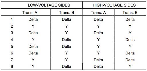 Table 1 – Operative Parallel Connections of Three-Phase Transformers
.
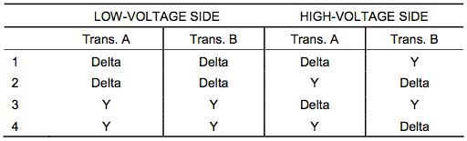 Table 2 – Inoperative Parallel Connections of Three-Phase Transformers
Wye-wye connected transformers are seldom, if ever, used to supply plant loads or as GSU units, due to the inherent third harmonic problems with this connection. Delta-delta, delta-wye, and wye-delta are used extensively at Reclamation facilities. Some rural electric associations use wye-wye connections that may be supplying reclamation structures in remote areas.
There are three methods to negate the third harmonic problems found with wye-wye connections:
- Primary and secondary neutrals can be connected together and grounded by one common grounding conductor.
- Primary and secondary neutrals can be grounded individually using two grounding conductors.
- The neutral of the primary can be connected back to the neutral of the sending transformer by using the transmission line neutral.
In making parallel connections of transformers, polarity markings must be followed. Regardless of whether transformers are additive or subtractive, connections of the terminals must be made according to the markings and according to the method of the connection (i.e., delta or wye).
CAUTION:
As mentioned above regarding paralleling single-phase units, when connecting additive polarity transformers to subtractive ones, connections will be in different locations from one transformer to the next.
.
Related articles
- Superconducting transformers
- Arc-resistant low voltage switchgear
- Substation, Its Function And Types
- General about motors
- History Of The Power Substations
5,072 views

MOXA | Video Surveillance in Power Substations
Power substations play a crucial role in delivering electricity to consumers by converting transmission voltage to the lower voltage used in homes and businesses. Since power plants are often located far from the population centers they serve, electricity needs to be transmitted across long distances at a higher voltage.
Power lines deliver electricity from the plant to the power substations where it is converted before being distributed to the local community. It is therefore imperative that power substations are constantly monitored for safety and maintenance as they are often located near or in a populated area. This white paper explains the benefits of real-time video monitoring and IP video technology, as well as factors to consider in deploying an optimal IP video surveillance system for a power substation.
Video Surveillance Benefits
Since power substations are widely distributed and unmanned, remote monitoring is extremely crucial. Real-time video surveillance of power substations offers automatic monitoring and control capabilities in addition to enhancing remote monitoring applications with visual management. These capabilities not only save management costs for manpower, but also realize complete network automation.
Supervisory Control and Data Acquisition (SCADA) systems, which are already deployed in power substations to provide data about the system’s status, can be easily integrated with video surveillance technology. By installing a real-time video monitoring system at power substations, system administrators are able to receive visual data to complement the raw SCADA data. Real-time video monitoring can help ensure normal operations for power equipment, protect against intrusion and tampering by unauthorized personnel, and prevent accidents. For example, intruders, physical obstructions, or smoke indicating a fire can be seen via video so engineers no longer need to visit the site in-person each time to diagnose an anomaly, saving both time and costs.
Remote video surveillance systems can play an important role in monitoring equipment, detecting intruders, and responding to emergency situations. For example, video surveillance can be used to monitor the appearance of the power transformer and relay, fueling and flammable equipment, and the status of the isolation switch. Video surveillance can also monitor the security situation inside and outside the substation by detecting intruders through sound and visual monitoring. In addition, video surveillance can be integrated with the alarm system and RTU (remote terminal unit) over a SCADA system to provide real-time visual information to prevent accidents and assist emergency response personnel in the event of a fire.
Why IP Video?
In the past, video surveillance systems such as CCTV networks relied upon analog video cameras. Due to advances in video digitization and compression technologies, high quality digital video images can now be sent over Ethernet TCP/IP networks. By using such devices, system integrators can easily integrate video surveillance applications into their SCADA system. As a result, Internet Protocol (IP) video technology is the current trend in video surveillance systems. The benefits of IP video surveillance include:
One Network - Using the existing IP network saves cabling costs and increases installation flexibility, especially for widely distributed substations. Ethernet TCP/IP networks can accommodate a variety of I/O monitoring and control devices in addition to transmitting data, video, voice, and even power (PoE) over a single network.
One System - Integration with SCADA or alarm systems (such as fire, intrusion, etc.) increases monitoring efficiency and creates an event-driven video surveillance system. This means the video images can be displayed and recorded and real-time responses can be received when an event or alarm occurs.
Constructing an Optimal IP Video Surveillance System
Given the critical role played by power substations in our daily lives, it is important for the IP video solution to be well-designed to ensure that the video surveillance system works properly. System integrators should consider factors such as applicability, reliability, integration, and user-friendliness in order to construct an optimal IP video surveillance system.
Applicability – System integrators need to consider video requirements such as image viewing, recording, and analysis, as well as interoperability with other systems (such as SCADA, Access Control, etc.) when deploying an IP video surveillance system. They also need to know how many cameras are required for the system and whether IP cameras or video encoders are suitable for the application. Network transmission factors such as bandwidth, multicast, and IGMP requirements, and whether the project requires a single network or separate networks for data and video are also important. Central management concerns, including system resources (PCs, servers, cost, etc.), software requirements (pure video or video integrated with another system), storage capability and database management, and whether or not a decoder is required, should also be considered.
Reliability - Since video monitoring is used to ensure safety and security in remote and disperse locations, reliability is a key factor in designing an optimal IP video surveillance system. Factors for reliability include surge protection and fiber transmission to reduce electromagnetic interference. Redundancy, high MTBF (meantime between failures) and IP protection are also important factors to consider for optimal reliability.
Integration - System integrators should consider integrating video surveillance into the central management system, as well as other systems, including SCADA/HMI, remote monitoring, and access control. This not only reduces cabling and network installation costs, but also makes central management and control easier to handle for system administrators. Interoperation with other devices for event-driven video monitoring is another benefit. For example, the system can begin recording video once a card reader or sensor is activated.
User-friendliness - IP video involves new applications and technologies that power system administrators need to learn. For this reason, it is recommended that system integrators choose ready-to-use hardware and software solutions to reduce the time needed to set up an IP video surveillance system. Not only does this simplify the system integrator’s task, but it will also be easier for system administrators to learn and use.

Video Surveillance in Power Substations
VPort Solutions
Moxa’s VPort industrial video networking solutions include video encoders and decoders, IP cameras, and IP video surveillance software designed for mission-critical video surveillance applications. Since most mission-critical application environments are demanding, the rugged design features of Moxa’s VPort solutions are particularly suitable for these kinds of applications.
Video servers – Digital video images require large data files, so video compression (reducing the quantity of data used to represent video images) is required for transmission and storage. Video servers include encoders and decoders. Encoders are used to convert analog video images from cameras into an easy to transfer digital format such as MJPEG or MPEG4. Decoders are used to convert images from compressed formats (MJPEG or MPEG4) back into analog for use with legacy monitors or displays.
IP cameras – IP cameras bypass the need for video encoders because the images are automatically encoded into a digital format (MJPEG or MPEG4) by the camera itself, and are easily transferred via Ethernet/Internet. Moxa’s VPort series of IP camera offers a wide operating temperature range of -40 to 50°C without the need for a fan or heater, IP66-rating for rain and dust protection, one camera lens for both day and night use, up to 30 frames per second at 720 x 480 resolution, and direct-wired power input and PoE (power over Ethernet) for power redundancy. Moxa’s industrial-grade video servers offer 12/24 VDC or 24 VAC redundant power inputs, DIN-Rail mounting and panel mounting accessories, IP30 protection, -40 to 75°C operating temperature range for T models, and RJ45 or fiber optic Ethernet ports.
Software – Moxa’s SoftDVR Surveillance Software, which includes SoftDVR Lite (4-ch) and SoftDVR Pro (16-ch), is designed for IP-based video surveillance systems. The client/server-based network infrastructure makes it easy to build a user-friendly video surveillance system. SoftDVR offers multi-screen viewing, event-driven recording, easy to use search and playback, data storage to network hard disks, scheduling feature for recording and alarm activation, and remote access by web browser.
SDK – Most video surveillance systems require customized video management functions, or must be integrated with other applications such as SCADA, access control systems, and fire alarms. For this reason, a user-friendly SDK (software development kit) is a good tool to have available for building customized video management systems. Moxa’s VPort SDK, which includes CGI Commands, ActiveX, and a C library, is available free of charge to system integrators and third-party software developers. Learning to use the Moxa VPort SDK is easy, and detailed documentation and sample code is provided for quick reference.
Summary
Transmitting video, voice, and data simultaneously over Ethernet/Internet is becoming a standard feature due to the ever-increasing popularity of IP networks. Versatile and advanced video digitizing and compression technologies, such as MJPEG and MPEG4, are also making it possible to migrate analog CCTV surveillance systems to IP-based platforms.
Power substations play an instrumental role in delivering electricity from power plants to end-users, so managing and ensuring the safety and security of these installations through an optimal video surveillance system is imperative. Since power substations are unmanned and widely distributed installations, video surveillance grants system administrators visual management capabilities in addition to data management provided by existing central control systems that only provide raw quantitative data. The versatility of IP video technology and its ability to be integrated with existing central control systems make it an attractive option for remote video monitoring in power substation applications.
.
SOURCE: MOXA, Harry Hsiao, Product Manager at Moxa; www.moxa.com; harry.hsiao@moxa.com
.
Related articles
- PLC-Based Monitoring Control System for Three-Phase Induction Motors Fed by PWM Inverter
- Energy management
- What is PowerLogic System?
- Cost benefits of AC drives
- Testing performances of IEC 61850 GOOSE messages
16,595 views

Caterpillar C175 Diesel Generator 2-4MW
The C175 family of diesel generator sets offers the most power you can get in any single high-speed package: 2-4MW.
One of the most significant components in the development of the C175 was the integration of ACERT™ Technology into the engine platform.
ACERT Technology is a synergistic approach utilizing a suite of complementary building block technologies that can be individually adapted to accommodate a specific application. In recent years, Caterpillar has spent more than $1 billion on the development of clean diesel technologies. Today, more than 330,000 engines are currently in operation with ACERT Technology, accumulating more than 2 million hours of use each day.
With the C175, the building blocks of ACERT Technology have been tailored to meet the current and pending emissions requirements of stationary diesel generator sets in a variety of applications.
Advantages
Thousands of hours of customer research created the foundation for the C175 design concept.
Some of the major advantages of the C175 family include:
- Proven Reliability with platform based on industry standard Cat® 3500 series, and supported by thousands of hours of lab and field-testing.
- Wider Power Range including 2000kW to 4000kW @ 1500 and 1800 rpm.
- Power Generation at Higher Speed than traditional medium speed products in the same power range.
- Higher Power Density equals more output from a given engine displacement / footprint, resulting in lower installed cost.
- Complete Package including SR5 generators, EMCP3 package controls and package/remote radiator with flexible controls packaging options simplifies installation.
- Lower Emissions meet U.S. EPA Tier 2 standards with a line of sight to meet U.S. EPA Tier 4 and EU Stage IIIB emissions levels.
- Lower Maintenance Costs due to increased oil change intervals, longer life (durability) of components and longer top end as well as full overhaul periods.
- Lower Operating Costs due to lower brake specific fuel consumption than competitive products.
- Systems Integration. The C175 electrical system components are engineered to work together with a wide range of products such as Uninterruptible Power Supplies (UPS), Automatic Transfer Switches (ATS), switchgear, remote monitoring services and customer building SCADA systems.
- Extensive Product Support from a worldwide dealer network with 24/7/365 parts and service availability.
Design Features
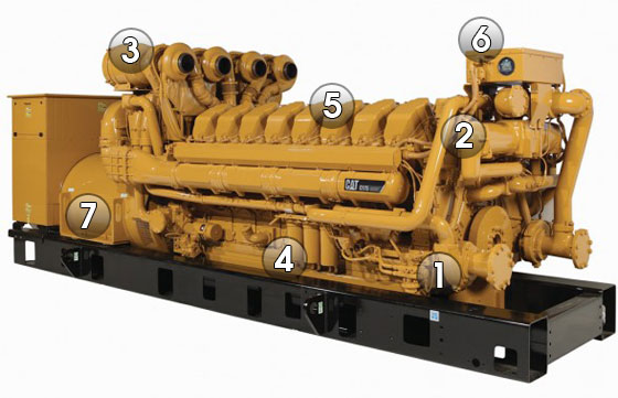
1. Fuel System

C175 - Fuel System
The new C175 engine features a Cat® Common Rail Fuel System designed specifically for this engine platform.
Full Control of Both Fuel Delivery and Fuel Pressure At Any Load or Speed results in superior transient response and block load acceptance, as well as shorter recovery time.
More Compact single camshaft that is used only to open the intake and exhaust valves. It features a simpler injection design with no pumping function necessary.
Improved Cold Start Capability uses higher pressures at low speeds and produces less smoke.
“Fluid Containment” Design. The high-pressure lines and rails are designed to provide outer concentric low-pressure containment. If a leak occurs in the high-pressure section, it leaks back to the outer low-pressure section and drains back to the tank.
Integrated Manifold or Monoblock offers a single point of connection to the engine, which eliminates leak paths while improving reliability.
Fuel Cooler Eliminated. Unlike the unit injector system, the Common Rail System used on the C175 does not require excess bypass fuel to cool the injector since injection pressure load is taken off the injector. The result is a reduction of heat generation in the return fuel and reduction in fuel flow rate by a factor of 4 when compared to the unit injector system. This eliminates the need for a fuel cooler in most cases.
Improved Fuel Filters. The C175 uses an eco-friendly fuel filter system. Instead of throwing away the whole canister, only the disposable non-metallic element inside the canister is changed.
Electronic Fuel Priming Pump is Engine Control Module (ECM)-controlled and offered as standard equipment. No manual effort is required to pump the fuel, so it’s more convenient and requires less operator effort.
2. Cooling System

C175 - Cooling System
The design philosophy for the Cat® C175 cooling system is to minimize heat rejection by cooling only the parts that require cooling.
Inlet-Regulated System. The C175 features an innovative design unique to Caterpillar. The system senses the temperature at the inlet and controls the output providing more consistent temperatures and better control of oil viscosity than an outlet-regulated system.
Electronic Fluid Temperature Controller regulates inlet temperature of the coolant and allows for troubleshooting without removing the thermostat. Improved diagnostics enable the operator to pinpoint a problem quickly, which increases reliability and uptime.
Integral Water Supply and Return Manifold are built into the engine block to minimize connection points and bolted joints. This design helps contain fluids and improves overall engine reliability and serviceability.
Two-Stage After-Cooler. The first stage is cooled by a jacket water circuit and the second stage has a two-pass separate circuit. The after-cooler is constructed with tube fin cores that are more robust compared to the traditional bar plate fin design. The tubes of the core can be cleaned without removing the core from the engine, and the core can be remanufactured. The tubes also have more surface area per volume and less pressure drop, resulting in more efficient cooling. This after-cooler design also minimizes the size of the SCAC circuit, thereby reducing the size of the radiator. The location of the first stage jacket water core provides protection from high air temperatures. These features improve the durability and reliability of the cooling system.
3. Air Management

C175 - Air Management
Air management is one of the ACERT™ Technology building blocks used on the Cat® C175 engine.
Crossflow Head provides separation between both the intake and exhaust ports and manifolds. The outboard air manifold location eliminates re-heating of intake air by preventing heat transfer from the exhaust to the intake. This results in reduced charge air temperature and increased charge air density, enabling higher power density as well as reducing SCAC cooling.
Taller Head accommodates larger ports and helps direct a large amount of cool air into the cylinder with the least resistance, resulting in the best port performance of any engine in the world. The taller head also accommodates increased valve lift of 22mm compared to 18mm on the Cat 3500, further improving breathing.
Improved Breathing. The tall crossflow head results in a greater amount of cooler air in and out of the engine, which helps produce higher power ratings and lower emissions. This, along with lower air pumping losses, results in lower fuel consumption.
New Generation of Turbochargers designed specifically for the C175. Four single-stage turbochargers provide a higher pressure ratio in a single stage. The turbocharger includes a cast titanium impeller and an improved bearing system that provides a higher load-bearing capacity and greater reliability, while increasing efficiency by 5% and extending the component life when compared to traditional cast aluminum impellers.
4. Lube System

C175 - Lube Management
The C175 lube system features two piston-cooling jets per piston.
A large capacity oil pump pressure regulation valve allows the engine to maintain optimum oil pressure at all speeds, loads and throughout the life of the engine, ultimately increasing durability.
.
.
.
5. Core Engine Components

C175 - Core Engine Components
The components of the new C175 centerline engine are designed for higher strength, durability and compactness.
Crankshaft has a larger diameter to handle bigger loads. It is made of steel forged material and features induction hardened fillets and journals. Thrust plates are located at the rear end of the crankshaft to reduce motion inside of the coupling between the engine and generator.
Block is made of cast iron and provides increased strength and stiffness, and is lighter weight.
Mid-Support Liners provide stronger support to the liner and offer more efficient cooling by only cooling the top 25% of the cylinder liner. Mid-support liners allow for a smaller inside diameter of the combustion seal, as well as a higher position for the piston’s top ring. The result is reduced crevice volume, improved cooling and combustion efficiency, and reduced emissions. Mid-support liners allow the head bolts to be closer to the cylinder bore to minimize cylinder spacing and to create a more compact engine.
Cylinder Cuff is specially designed for improved durability. The ring of the “cuff” located at the top of the cylinder scrapes off carbon accumulation on the piston top end, preventing the carbon from polishing, scratching or seizing the liner. The cuff also helps reduce crevice volume beside the piston, resulting in lower emissions.
Cylinder Head is made of iron for added strength. The tall C175 head helps eliminate the external water manifold by returning the coolant to the cylinder block.
Head Gasket features a simplified two-piece (carrier seal and combustion seal) design, shortening service time, decreasing parts costs, and increasing reliability and durability.
Pistons and Rings feature increased oil flow to pistons for better cooling and higher power ratings. Rectangular piston rings provide a superior seal and less motion, resulting in less wear and longer life. Piston, rod and liner come out as one assembly, resulting in faster, easier service.
Connecting Rods. Large diameter fracture split connecting rods provide better alignment between the rod and cap, which eliminates the need for a special alignment procedure.
Bearings. Large main and rod bearings provide better seizure resistance and better tolerance of a wide range of oil temperatures. Larger rod bearing and main bearing are more scuff and seizure resistant.
6. Engine Management System

C175 - Engine Management System
The Cat® C175 utilizes much of the ACERT™ Technology electronics experience gained on small-bore engines and employs many new improvements and technologies more useful on large bore engines. The C175 Engine Management System exploits the power of modern control technology to improve reliability, exceed customer expectations and accommodate future customer requirements.
Engine Control Module (ECM). C175 engine controls use the latest version of the ADEM™ A4 ECM to deliver 50 times the computing power of its predecessor. Specific benefits include monitoring over 30 points on the engine, driving up to 20 injectors, protecting the engine, communicating over 100 engine parameters to the customer, diagnosing and reporting on engine health. The ECM uses the latest advancements in ACERT Technology to improve engine performance while reducing emissions.
Engine Controls and Datalink. Three primary controllers are temperature control module, fuel high-pressure controller and ECM. These are connected to the engine J1939 datalink.
Rigid Wiring Harness. Metal enclosed rigid wiring harness system protects critical engine circuits from accidental damage, reducing service calls and increasing reliability.
Controls Packaging. The standard panel is a rear-mounted EMCP 3.1 with the option to upgrade to the EMCP 3.2 or EMCP 3.3.
7. Generator

C175 - Generator
Caterpillar is introducing the next evolution of generators, the SR5 Series, with the introduction of the C175 generator sets. The SR5 Series 1800 and 3000 frame generators have been designed specifically to work with the C175 engines. The structural design is matched to the C175 engine. Torsional and linear vibration analysis and testing have been performed to ensure durability.
The SR5 generator’s insulation system has been improved to meet insulation Class H. SR5 generators feature 2/3-pitch as standard on all low, medium and high voltage generators. SR5 generators have IP23 particle ingress protection.
Generator Set Packaging. The C175 uses a fusible coupling to connect the generator to the engine. All engines, generators and controls are tested individually prior to assembly. Once assembled, the entire generator set package is tested before shipping to dealers to ensure quality.
Applications
The versatility of the C175 makes it ideal for a variety of applications.
- Continuous – A continuous rating has a typical load factor of 70% to 100% with no limit on the number of hours per year. Typical peak demand is 100% of continuous rated kW for 100% of operating hours. Typical applications include base load, utility or co-generation.
- Prime – A prime rating has a typical load factor of 60% to 70% with no limit on the number of hours per year. Typical peak demand is 100% of prime rated kW with 10% overload available for emergency use for up to one hour in 12. Typical applications include industrial, pumping, construction, peak shaving or co-generation.
- Standby – A standby rating has a typical load factor of 70% or less with variable load for about 200 hours per year,with a maximum expected usage of 500 hours per year. Typical peak demand is 80% of the standby rated kW with power available for the duration of an emergency outage. Typical applications include building service standby or emergency standby.
- Load Management – A load management rating has a typical load factor of 100% of the prime rating for a maximum of 500 hours per year. Typical peak demand is 100% of the load management rating, with no overload available. Typical applications include base load or peak shaving.
SOURCE: Caterpillar C175
.
Related articles
- Transformer Ratings
- Bus Joint Fundamentals
- Hydropower – Systems Overview (2)
- Transformer heating and cooling
- Comparison Between Vacuum and SF6 Circuit Breaker
31,728 views

Designing a quality grounding system is not only for the safety of employees but also provides the protection required for buildings and equipment.
Ungrounded systems may provide greater continuity of operations in the event of a ground fault. However, the second fault will most likely be more catastrophic than a grounded system fault. Whenever ungrounded systems are used in a facility, the maintenance personnel should receive training in how to detect and troubleshoot the first ground on an ungrounded system.
Electrical systems can be operated grounded or ungrounded, depending on the condition of the systems use. Electrical systems are grounded to protect circuits, equipment, and conductor enclosures from dangerous voltages and personnel from electrical shock. See NEC Sections 110-9, 110-10, 230-65, 250-1, and 250-2 that list the requirements to provide this protection.
“Grounded” means that the connection to ground between the service panel and earth has been made. Ungrounded electrical systems are used where the designer does not want the overcurrent protection device to clear in the event of a ground fault.
Ground detectors can be installed per NEC Section 250-5(b) FPN to sound an alarm or send a message to alert personnel that a ground fault has occurred on one of the phase conductors. Ground detectors will detect the presence of leakage current or developing fault current conditions while the system is still energized and operating. By warning of the need to take corrective action before a problem occurs, safe conditions can usually be maintained until an orderly shutdown is implemented.
Grounded Systems
Grounded systems are equipped with a grounded conductor that is required per NEC Section 250- 23(b) to be run to each service disconnecting means. The grounded conductor can be used as a current-carrying conductor to accommodate all neutral related loads. It can also be used as an equipment grounding conductor to clear ground faults per NEC Section 250-61(a).
A network of equipment grounding conductors is routed from the service equipment enclosure to all metal enclosures throughout the electrical system. The equipment grounding conductor carries fault currents from the point of the fault to the grounded bus in the service equipment where it is transferred to the grounded conductor. The grounded conductor carries the fault current back to the source and returns over the faulted phase and trips open the overcurrent protection device.
Note: A system is considered grounded if the supplying source such as a transformer, generator, etc., is grounded, in addition to the grounding means on the supply side of the service equipment disconnecting device per NEC Sections 250-23(a) or 250-26 for seperately derived systems.
The neutral of any grounded system serves two main purposes: (1) it permits the utilization of line- to-neutral voltage and thus will serve as a current-carrying conductor to carry any unbalanced current, and (2) it plays a vital role in providing a low-impedance path for the flow of fault currents to facilitate the operation of the overcurrent devices in the circuit. (See picture below).
Consideration should be given to the sizing of the neutral conductor for certain loads due to the presence of harmonic currents (See NEC Sections 210-4 and 310-10).
 conductor routed between the supply transformer and the service equipment.")
A grounded system is equipped with a grounded (neutral) conductor routed between the supply transformer and the service equipment.
Ungrounded Systems
Ungrounded systems operate without a grounded conductor. In other words, none of the circuit conductors of the electrical system are intentionally grounded to an earth ground such as a metal water pipe, building steel, etc. The same network of equipment grounding conductors is provided for ungrounded systems as for solidly grounded electrical systems. However, equipment grounding conductors (EGCs) are used only to locate phase-to-ground faults and sound some type of alarm.
Therefore, a single sustained line-to-ground fault does not result in an automatic trip of the overcurrent protection device. This is a major benefit if electrical system continuity is required or if it would result in the shutdown of a continuous process. However, if an accidental ground fault occurs and is allowed to flow for a substantial time, overvoltages can develop in the associated phase conductors. Such an overvoltage situation can lead to conductor insulation damage, and while a ground fault remains on one phase of an ungrounded system, personnel contacting one of the other phases and ground are subjected to 1.732 times the voltage they would experience on a solidly neutral grounded system. (See picture below).
Note: All ungrounded systems should be equipped with ground detectors and proper maintenance applied to avoid, as far as practical, the overcurrent of a sustained ground fault on ungrounded systems. If appropriate maintenance is not provided for ungrounded systems, a grounded system should be installed to ensure that ground faults will be cleared and the safety of circuits, equipment, and that personnel safety is ensured.
 conductor routed between the supply transformer and the service equipment because the supply transformer is not earth grounded.")
An ungrounded system does not have a grounded (neutral) conductor routed between the supply transformer and the service equipment because the supply transformer is not earth grounded.
High impedance grounding
Electrical systems containing three-phase, three-wire loads, as compared to grounded neutral circuit conductor loads, can be equipped with a high-impedance grounded system. High-impedance grounded systems shall not be used unless they are provided with ground fault indicators or alarms, or both, and qualified personnel are available to quickly locate and eliminate such ground faults.
Ground faults must be promptly removed or the service reliability will be reduced. See NEC Section 250-27 for requirements pertaining to installing a high-impedance grounding system. (See picture below).
 conductor and the grounding electrode conductor, which is used to regulate fault current.")
A high-impedance grounding system has a high-impedance unit, installed between the grounded (neutral) conductor and the grounding electrode conductor, which is used to regulate fault current.
Source: DOE HANDBOOK – ELECTRICAL SAFETY
.
Related articles
- Shielding Of Power Cables
- ABB Feeder Protection REF615 ANSI
- Line Protection With Distance Relays
- UPS design criteria and selection
- Arc-resistant low voltage switchgear
31,022 views

Power transformer
In a real transformer, some power is dissipated in the form of heat. A portion of these power losses occur in the conductor windings due to electrical resistance and are referred to as copper losses. However, so-called iron losses from the transformer core are also important. The latter result from the rapid change of direction of the magnetic field, which means that the microscopic iron particles must continually realign themselves technically, their magnetic moment—in the direction of the field (or flux). Just as with the flow of charge, this realignment encounters friction on the microscopic level and therefore dissipates energy, which becomes tangible as heating of the material.
Taking account of both iron and copper losses, the efficiency (or ratio of electrical power out to electrical power in) of real transformers can be in the high 90% range. Still, even a small percentage of losses in a large transformer corresponds to a sig- nificant amount of heat that must be dealt with. In the case of small transformers inside typical household adaptors for low-voltage d.c. appliances, we know that they are warm to the touch. Yet they transfer such small quantities of power that the heat is easily dissipated into the ambient air . By contrast, suppose a 10MVA transformer at a distribution substation operates at an efficiency of 99%: A 1% loss here corresponds to a staggering 100 kW.
In general, smaller transformers like those on distribution poles are passively cooled by simply radiating heat away to their surroundings, sometimes assisted by radiator vanes that maximize the available surface area for removing the heat.
Large transformers like those at substations or power plants require the heat to be removed from the core and windings by active cooling, generally through circulat- ing oil that simultaneously functions as an electrical insulator.
The capacity limit of a transformer is dictated by the rate of heat dissipation. Thus, as is true for power lines, the ability to load a transformer depends in part on ambient conditions including temperature, wind, and rain. For example, if a transformer appears to be reaching its thermal limit on a hot day, one way to salvage the situation is to hose down its exterior with cold water—a procedure that is not “by the book,” but has been reported to work in emergencies. When transformers are operated near their capacity limit, the key variable to monitor is the internal or oil temperature. This task is complicated by the problem that the temperature may not be uniform throughout the inside of the transformer, and damage can be done by just a local hot spot. Under extreme heat, the oil can break down, sustain an electric arc, or even burn, and a transformer may explode.
A cooling and insulating fluid for transformers has to meet criteria similar to those for other high-voltage equipment, such as circuit breakers and capacitors: it must conduct heat but not electricity; it must not be chemically reactive; and it must not be easily ionized, which would allow arcs to form. Mineral oil meets these criteria fairly well, since the long, nonpolar molecules do not readily break apart under an electric field.
Another class of compounds that performs very well and has been in widespread use for transformers and other equipment is polychlorinated biphenyls, commonly known as PCBs. Because PCBs and the dioxins that contaminate them were found to be carcinogenic and ecologically toxic and persistent, they are no longer manufactured in the United States; the installation of new PCB-containing utility equipment has been banned since 1977.11 However, much of the extant hardware predates this phase-out and is therefore subject to careful maintenance and disposal procedures (somewhat analogous to asbestos in buildings).
Introduced in the 1960s, sulfur hexafluoride (SF6) is another very effective arc-extinguishing fluid for high-voltage equipment. SF6 has the advantage of being reasonably nontoxic as well as chemically inert, and it has a superior ability to with- stand electric fields without ionizing. While the size of transformers and capacitors is constrained by other factors, circuit breakers can be made much smaller with SF6 than traditional oil-filled breakers. However, it turns out that SF6 absorbs thermal infrared radiation and thus acts as a greenhouse gas when it escapes into the atmos- phere; it is included among regulated substances in the Kyoto Protocol on global climate change. SF6 in the atmosphere also appears to form another compound by the name of trifluoromethyl sulfur pentafluoride (SF5CF3), an even more potent greenhouse gas whose atmospheric concentration is rapidly increasing.
COOLING EQUIPMENT

Transformer fan
Heat from core losses and copper losses must be dissipated to the environment. In dry type transformers, cooling is accomplished simply by circulating air around and through the coil and core assembly, either by natural convection or by forced air flow from fans. This cooling method is usually limited to low-voltage indoor transformers (5 kV and below) having a three-phase rating below 1500 KVA. At higher voltages, oil is required to insulate the windings, which prevents the use of air for cooling the core and coils directly. At higher KVA ratings, the losses are just too high for direct air cooling to be effective. In outdoor environments, direct air cooling would introduce unacceptable amounts of dirt and moisture into the windings.
Transformers come in various cooling classes, as defined by the industry standards. In recent years, there have been attempts to align the designa- tions that apply to transformers manufactured in North America with the IEC cooling-class designations. Table below gives the IEC designations and the earlier designations that are used in this book. All of the IEC designations use four letters. In some respects, the IEC designations are more descriptive than the North American designations because IEC makes a distinction between forced-oil/air cooled (OFAF) and directed-flow-air cooled (ODAF). Some people find using the four-letter designations somewhat awkward, and this book uses the earlier designations throughout.
In small oil-filled distribution transformers, the surface of the tank is sufficient for transferring heat from the oil to the air. Ribs are added to the tanks of some distribution transformers to increase the surface area of the tank and to improve heat transfer. Large distribution transformers and small power transformers generally require radiator banks to provide cooling. Regardless of whether the tank surface, ribs, or radiators are used, transformers that trans-fer heat from oil to air through natural convection are all cooling class OA transformers.
Radiators used on OA transformers generally have round cooling tubes or flat fins with large cross section areas in order to allow oil to flow by natural convection with minimal resistance. Hot oil from the core and coils rises to the top of the tank above the inlet to the radiator. Cool oil from the radiator sinks to the bottom of the radiator through the outlet and into the bottom of the core and coils. This process is called thermo-siphoning and the oil velocity is relatively slow throughout the transformer and radiators. For this reason, OA transformers have relatively large temperature gradients between the bot- tom oil and the top oil, and relatively large temperature gradients between the winding temperatures and the top oil temperature. Likewise, the air circulates through the radiator through natural convection, or is aided by the wind.
| Previous designation | IEC designation | Description |
| .OA | .ONAN | Oil-air cooled (self-cooled) |
| .FA | .ONAF | Forced-air cooled |
| .OA/FA/FA | .ONAN/ONAF/ONAF | Oil-air cooled (self-cooled), followed by two stages of forced-air cooling (fans) |
| .OA/FA/FOA | .ONAN/ONAF/OFAF | Oil-air cooled (self-cooled), followed by one stage of forced-air cooling (fans), followed by 1 stage of forced oil (oil pumps) |
| .OA/FOA | .ONAF/ODAF | Oil-air cooled (self-cooled), followed by one stage of directed oil flow pumps (with fans) |
| . OA/FOA/FOA | .ONAF/ODAF/ODAF | Oil-air cooled (self-cooled), followed by two stages of directed oil flow pumps (with fans) |
| .FOA | .OFAF | Forced oil/air cooled (with fans) rating only—no self-cooled rating |
| .FOW | .OFWF | Forced oil / water cooled rating only (oil / water heat exchanger with oil and wa- ter pumps)—no self-cooled rating |
| .FOA | .ODAF | Forced oil / air cooled rating only with di- rected oil flow pumps and fans—no self-cooled rating |
| .FOW | .ODWF | Forced oil / water cooled rating only (oil / water heat exchanger with directed oil flow pumps and water pumps)— no self-cooled rating |
As the transformer losses increase, the number and size of the radiators that are required to cool the oil must increase. Eventually, a point is reached where wind and natural convection are not adequate to remove the heat and air must be forced through the radiators by motor-driven fans. Transformers that have forced air cooling are cooling class FA transformers. FA transform- ers require auxiliary power to run the fan motors, however, and one of the advantages of OA transformers is that they require no auxiliary power for cooling equipment. Since additional cooling is not usually needed until the transformer is heavily loaded, the fans on most FA transformers are turned off until temperatures exceed some threshold value, so under light load the transformer is cooled by natural convection only. These transformers are cool- ing class OA/FA transformers.
Some transformers are cooled by natural convection below temperature T1, turn on one stage of fans at a higher temperature T2 and turn on a second stage of fans at an even higher temperature T3. These transformers are cooling class OA/FA/FA transformers. The direction of air flow in forced-air units is either horizontally outward or vertically upward. The vertical flow pattern has the advantage of being in the same direction as the natural air convection, so the two air flows will reinforce each other.
Although the cooling capacity is greatly increased by the use of forced air, increasing the loading to take advantage of the increased capacity will increase the temperature gradients within the transformer. A point is reached where the internal temperature gradients limit the ability to increase load any further. The solution is to increase the oil velocity by pumping oil as well as forcing air through the radiators. The usual pump placement is at the bottom of the radiators, forcing oil from the radiator outlets into the bottom of he transformer tank in the same direction as natural circulation but at a much higher velocity. Such transformers are cooling class FOA transformers. By directing the flow of oil within the transformer windings, greater cooling effi- ciency can be achieved. In recognition of this fact, the calculation of hot-spot temperatures is modified slightly for directed-flow cooling class transformers.
As in forced-air designs, forced-oil cooling can be combined with OA cooling (OA/FOA) or in two stages (OA/FOA/FOA). A transformer having a stage of fans and a stage of oil pumps that are switched on at different temperatures would be a cooling class OA/FA/FOA transformer.
The radiator design on FOA transformers can differ substantially with the radiator design on FA transformers. Since the oil is pumped under consid- erable pressure, the resistance to oil flow is of secondary importance so the radiator tubes can be designed to maximize surface area at the expense of cross section area. FOA radiators are sometimes called coolers instead, and tend to resemble automotive radiators with very narrow spaces between the cooling tubes and flat fins in the spaces between the cooling tubes to provide additional surface area. The comparison of the two types is illustrated in picture left (OA/FA type) and right (FOA type).
 OA/FA radiator construction. The large radiator tubes minimize restric- tion of oil flow under natural convection. The fan is shown mounted at the bottom with air flow directed upward. |  FOA cooler construction. The oil is forced through narrow tubes from top to bottom by means of oil pumps. The cooling fans direct air horizontally outward. | |
Cooling equipment requires maintenance in order to run efficiently and provide for a long transformer life. There is the obvious need to main- tain the fans, pumps, and electrical supply equipment. The oil coolers them- selves must be kept clean as well, especially FOA-type coolers. Many transformers have overheated under moderate loads because the cooling fins were clogged with insect and bird nests, dust, pollen, and other debris. For generator step-up transformers, where the load is nearly at nameplate rating continuously, steam-cleaning the coolers once every year is a good mainte- nance practice.
.
Related articles
- Transformer Ratings
- Substation, Its Function And Types
- ABB Power Transformers – A guide to manufacturing
- UPS design criteria and selection
- What is PowerLogic System?
10,327 views

Transformator shot with thermovision camera
Substation ventilation is generally required to dissipate the heat produced by transformers and to allow drying after particularly wet or humid periods. However, a number of studies have shown that excessive ventilation can drastically increase condensation. Ventilation should therefore be kept to the minimum level required. Furthermore, ventilation should never generate sudden temperature variations that can cause the dew point to be reached. For this reason: Natural ventilation should be used whenever possible. If forced ventilation is necessary, the fans should operate continuously to avoid temperature fluctuations. Guidelines for sizing the air entry and exit openings of substations are presented hereafter.
Calculation methods

Natural ventilation
A number of calculation methods are available to estimate the required size of substation ventilation openings, either for the design of new substations or the adaptation of existing substations for which condensation problems have occurred.
The basic method is based on transformer dissipation. The required ventilation opening surface areas S and S’ can be estimated using the following formulas:
![]()
where:
S = Lower (air entry) ventilation opening area [m2] (grid surface deducted)
S’= Upper (air exit) ventilation opening area [m2] (grid surface deducted)
P = Total dissipated power [W]
P is the sum of the power dissipated by:
- The transformer (dissipation at no load and due to load)
- The LV switchgear
- The MV switchgear
H = Height between ventilation opening mid-points [m]
Note:
This formula is valid for a yearly average temperature of 20 °C and a maximum altitude of 1,000 m.
It must be noted that these formulas are able to determine only one order of magnitude of the sections S and S’, which are qualified as thermal section, i.e. fully open and just necessary to evacuate the thermal energy generated inside the MV/LV substation. The pratical sections are of course larger according ot the adopted technological solution.
Indeed, the real air flow is strongly dependant:
- on the openings shape and solutions adopted to ensure the cubicle protection index (IP): metal grid, stamped holes, chevron louvers,…
- on internal components size and their position compared to the openings: transformer and/or retention oil box position and dimensions, flow channel between the components, …
- and on some physical and environmental parameters: outside ambient temperature, altitude, magnitude of the resulting temperature rise.
The understanding and the optimization of the attached physical phenomena are subject to precise flow studies, based on the fluid dynamics laws, and realized with specific analytic software.
Example:
Transformer dissipation = 7,970 W LV switchgear dissipation = 750 W MV switchgear dissipation = 300 W The height between ventilation opening mid-points is 1.5 m.
Calculation:
Dissipated Power P = 7,970 + 750 + 300 = 9,020 W
![]()
Ventilation opening locations
To favour evacuation of the heat produced by the transformer via natural convection, ventilation openings should be located at the top and bottom of the wall near the transformer. The heat dissipated by the MV switchboard is negligible. To avoid condensation problems, the substation ventilation openings should be located as far as possible from the switchboard.
 «Over» ventilated MV/LV Substation. The MV cubicle is subjected to sudden temperature variations. |  Substation with adapted ventilation. The MV cubicle is no longer subjected to sudden temperature variations. |
If the MV switchboard is separated from the transformer, the room containing the switchboard requires only minimal ventilation to allow drying of any humidity that may enter the room.
Type of ventilation openings
To reduce the entry of dust, pollution, mist, etc., the substation ventilation openings should be equipped with chevron-blade baffles. Always make sure the baffles are oriented in the right direction.
MV cubicle ventilation
Any need for natural ventilation is taken into account by the manufacturer in the design of MV cubicles. Ventilation openings should never be added to the original design.
Source:
Instruction: Medium Voltage equipment on sites exposed to high humidity and/or heavy pollution by Schneider Electric
.
Related articles
- ABB Power Transformers – A guide to manufacturing
- Transformer Oil Diagnostics
- Guide To Low Voltage Busbar Trunking Systems (1)
- Dry-Type disc wound transformers in MV applications
- Substation, Its Function And Types

Air Insulated Substations
Various factors affect the reliability of a substation, one of which is the arrangement of the switching devices. Arrangement of the switching devices will impact maintenance, protection, initial substation development, and cost. There are six types of substation bus switching arrangements commonly used in air insulated substations:
1. Single bus
2. Double bus, double breaker
3. Main and transfer (inspection) bus
4. Double bus, single breaker
5. Ring bus
6. Breaker and a half
1. Single Bus Configuration

Single Bus Configuration
This arrangement involves one main bus with all circuits connected directly to the bus. The reliability of this type of an arrangement is very low. When properly protected by relaying, a single failure to the main bus or any circuit section between its circuit breaker and the main bus will cause an outage of the entire system. In addition, maintenance of devices on this system requires the de-energizing of the line connected to the device. Maintenance of the bus would require the outage of the total system, use of standby generation, or switching to adjacent station, if available. Since the single bus arrangement is low in reliability, it is not recommended for heavily loaded substations or substations having a high availability requirement. Reliability of this arrangement can be improved by the addition of a bus tiebreaker to minimize the effect of a main bus failure.
2. Double Bus, Double Breaker Configuration

Double bus, double breaker
This scheme provides a very high level of reliability by having two separate breakers available to each circuit. In addition, with two separate buses, failure of a single bus will not impact either line. Maintenance of a bus or a circuit breaker in this arrangement can be accomplished without interrupting either of the circuits. This arrangement allows various operating options as additional lines are added to the arrangement; loading on the system can be shifted by connecting lines to only one bus. A double bus, double breaker scheme is a high-cost arrangement, since each line has two breakers and requires a larger area for the substation to accommodate the additional equipment. This is especially true in a low profile configuration. The protection scheme is also more involved than a single bus scheme.
3. Main and Transfer Bus Configuration

Main and transfer bus configuration
This scheme is arranged with all circuits connected between a main (operating) bus and a transfer bus (also referred to as an inspection bus). Some arrangements include a bus tie breaker that is connected between both buses with no circuits connected to it. Since all circuits are connected to the single, main bus, reliability of this system is not very high. However, with the transfer bus available during maintenance, de-energizing of the circuit can be avoided. Some systems are operated with the transfer bus normally de-energized. When maintenance work is necessary, the transfer bus is energized by either closing the tie breaker, or when a tie breaker is not installed, closing the switches connected to the transfer bus. With these switches closed, the breaker to be maintained can be opened along with its isolation switches. Then the breaker is taken out of service. The circuit breaker remaining in service will now be connected to both circuits through the transfer bus. This way, both circuits remain energized during maintenance. Since each circuit may have a different circuit configuration, special relay settings may be used when operating in this abnormal arrangement.
When a bus tie breaker is present, the bus tie breaker is the breaker used to replace the breaker being maintained, and the other breaker is not connected to the transfer bus. A shortcoming of this scheme is that if the main bus is taken out of service, even though the circuits can remain energized through the transfer bus and its associated switches, there would be no relay protection for the circuits. Depending on the system arrangement, this concern can be minimized through the use of circuit protection devices (reclosure or fuses) on the lines outside the substation.
This arrangement is slightly more expensive than the single bus arrangement, but does provide more flexibility during maintenance. Protection of this scheme is similar to that of the single bus arrangement. The area required for a low profile substation with a main and transfer bus scheme is also greater than that of the single bus, due to the additional switches and bus.
4. Double Bus, Single Breaker Configuration

Double bus, single breaker configuration
This scheme has two main buses connected to each line circuit breaker and a bus tie breaker. Utilizing the bus tie breaker in the closed position allows the transfer of line circuits from bus to bus by means of the switches. This arrangement allows the operation of the circuits from either bus. In this arrangement, a failure on one bus will not affect the other bus. However, a bus tie breaker failure will cause the outage of the entire system. Operating the bus tie breaker in the normally open position defeats the advantages of the two main buses. It arranges the system into two single bus systems, which as described previously, has very low reliability. Relay protection for this scheme can be complex, depending on the system requirements, flexibility, and needs. With two buses and a bus tie available, there is some ease in doing maintenance, but maintenance on line breakers and switches would still require outside the substation switching to avoid outages.
5. Ring Bus Configuration

Ring bus configuration
In this scheme, as indicated by the name, all breakers are arranged in a ring with circuits tapped between breakers. For a failure on a circuit, the two adjacent breakers will trip without affecting the rest of the system. Similarly, a single bus failure will only affect the adjacent breakers and allow the rest of the system to remain energized. However, a breaker failure or breakers that fail to trip will require adjacent breakers to be tripped to isolate the fault. Maintenance on a circuit breaker in this scheme can be accomplished without interrupting any circuit, including the two circuits adjacent to the breaker being maintained. The breaker to be maintained is taken out of service by tripping the breaker, then opening its isolation switches. Since the other breakers adjacent to the breaker being maintained are in service, they will continue to supply the circuits. In order to gain the highest reliability with a ring bus scheme, load and source circuits should be alternated when connecting to the scheme. Arranging the scheme in this manner will minimize the potential for the loss of the supply to the ring bus due to a breaker failure. Relaying is more complex in this scheme than some previously identified. Since there is only one bus in this scheme, the area required to develop this scheme is less than some of the previously discussed schemes. However, expansion of a ring bus is limited, due to the practical arrangement of circuits.
6. Breaker-and-a-Half Configuration

Breaker and a half configuration
The breaker-and-a-half scheme can be developed from a ring bus arrangement as the number of circuits increases. In this scheme, each circuit is between two circuit breakers, and there are two main buses. The failure of a circuit will trip the two adjacent breakers and not interrupt any other circuit. With the three breaker arrangement for each bay, a center breaker failure will cause the loss of the two adjacent circuits. However, a breaker failure of the breaker adjacent to the bus will only interrupt one circuit.
Maintenance of a breaker on this scheme can be performed without an outage to any circuit. Further- more, either bus can be taken out of service with no interruption to the service. This is one of the most reliable arrangements, and it can continue to be expanded as required. Relaying is more involved than some schemes previously discussed. This scheme will require more area and is costly due to the additional components.
| Configuration | Reliability | Cost | Available area |
| .Single bus | Least reliable — single failure can cause complete outage | Least cost — fewer components | Least area — fewer components |
| .Double bus | Highly reliable — duplicated components; single failure normally isolates single component | High cost — duplicated components | Greater area — twice as many components |
| .Main bus and .transfer | Least reliable — same as Single bus, but flexibility in operating and maintenance with transfer bus | Moderate cost — fewer components | Low area requirement — fewer components |
| .Double bus, .single breaker | Moderately reliable — depends on arrangement of components and bus | Moderate cost — more components | Moderate area — more components |
| .Ring bus | High reliability — single failure isolates single component | Moderate cost — more components | Moderate area — increases with number of circuits |
| .Breaker and a.half | Highly reliable — single circuit failure isolates single circuit, bus failures do not affect circuits | Moderate cost — breaker-and-a-half for each circuit | Greater area — more components per circuit |
.
Related articles
- ABB launches new generation 420kV gas insulated switchgear
- Substation, Its Function And Types
- Current Switching with High Voltage Air Disconnector
- GE AKD-20 Low-Voltage Switchgear
- Maintenance Of High Voltage Circuit Breakers


