
22,480 views

Standard IEC 60947-2 | Circuit Breakers
This standard applies to circuit-breakers, the main contacts of which are intended to be connected to circuits, the rated voltage of which does not exceed 1000 VAC or 1500 VDC.; it also contains additional requirements for integrally fused circuit-breakers.
It applies whatever the rated currents, the method of construction or the proposed applications of the circuit-breakers may be.
Changes in dependability needs and technologies have led to a marked increase in standard requirements for industrial circuit-breakers.
Conformity with standard IEC 947-2, renamed IEC 60947-2 in 1997, can be considered as an ‘all-risk’ insurance for use of circuit-breakers. This standard has been approved by all countries.
The principles
Standard IEC 60947-2 is part of a series of standards defining the specifications for LV electrical switchgear:
- the general rules IEC 60947-1, that group the definitions, specifications and tests common to all LV industrial switchgear.
- the product standards IEC 60947-2 to 7, that deal with specifications and tests specific to the product concerned. Standard IEC 60947-2 applies to circuit-breakers and their associated trip units. Circuit-breaker operating data depend on the trip units or relays that control their opening in specific conditions.
This standard defines the main data of industrial circuit-breakers:
- their classification: utilisation category, suitability for isolation, etc.
- the electrical setting data
- the information useful for operation
- the design measures
- coordination of protection devices
The standard also draws up series of conformity tests to be undergone by the circuitbreakers. These tests, which are very complete, are very close to real operating conditions. Conformity of these tests with standard IEC 60947-2 is verified by accredited laboratories.
Table of main data (appendix K IEC 60947-2):
")
Circuit-breaker category
Category IEC 60947-2 defines two circuit-breaker categories:
- category A circuit-breakers, for which no tripping delay is provided. This is normally the case of moulded case circuit-breakers. These circuit-breakers can provide current discrimination.
- category B circuit-breakers, for which, in order to provide time discrimination, tripping can be delayed (up to 1 s) for all short-circuits of value less than the current Icw.
This is normally the case of power or moulded case circuit-breakers with high ratings. For circuit-breakers installed in the MSBs, it is important to have an lcw equal to lcu in order to naturally provide discrimination up to full ultimate breaking capacity Icu.
Reminders of standard-related electrical data
The setting data are given by the tripping curves. These curves contain some areas limited by the following currents.

- Rated operational current (In)
In (in A rms) = maximum uninterrupted current withstood at a given ambient temperature without abnormal temperature rise.
E.g. 125 A at 40 °C - Adjustable overload setting current (lr)
Ir (in A rms) is a function of ln. lr characterises overload protection. For operation in overload, the conventional non-tripping currents lnd and tripping currents ld are:- Ind = 1.05 Ir
- Id = 1.30 Ir
Id is given for a conventional tripping time. For a current greater than ld, tripping by thermal effect will take place according to an inverse time curve. Ir is known as Long Time Protection (LTP).
Short time tripping setting current (Isd)
Isd (in kA rms) is a function of Ir. lsd characterises short-circuit protection. The circuit breaker opens according to the short time tripping curve:- either with a time delay tsd,
- or with constant I2t,
- or instantaneously (similar to instantaneous protection).
Isd is known as Short Time Protection or lm.
- Instantaneous tripping setting current (Ii)
Ii (in kA) is given as a function of ln. It characterises the instantaneous short-circuit protection for all circuit-breaker categories. For high overcurrents (short-circuits) greater than the li threshold, the circuit-breaker must immediately break the fault current.
.
This protection device can be disabled according to the technology and type of circuit-breaker (particularly B category circuit-breakers).

Table for calculation of asymmetrical short-circuits (IEC 60947.2 para. 4.3.5.3.)

- Rated short-circuit making capacity(*) (Icm)
Icm (peak kA) is the maximum value of the asymmetrical short-circuit current that the circuit-breaker can make and break. For a circuit-breaker, the stress to be managed is greatest on closing on a short-circuit. - Rated ultimate breaking capacity(*) (Icu)
Icu (kA rms) is the maximum short-circuit current value that the circuit-breaker can break. It is verified according to a sequence of standardised tests. After this sequence, the circuit-breaker must not be dangerous. This characteristic is defined for a specific voltage rating Ue. - Rated service breaking capacity(*) (Ics)
Ics (kA rms) is given by the manufacturer and is expressed as a % of Icu. This performance is very important as it gives the ability of a circuit-breaker to provide totally normal operation once it has broken this short-circuit current three times. The higher Ics, the more effective the circuit-breaker. - Rated short time withstand current(*) (Icw)
Defined for B category circuit-breakers
Icw (kA rms) is the maximum short-circuit current that the circuit-breaker can withstand for a short period of time (0.05 to 1 s) without its properties being affected. This performance is verified during the standardised test sequence.
.
(*) These data are defined for a specific voltage rating Ue.
Circuit-breaker coordination
The term coordination concerns the behaviour of two devices placed in series in electrical power distribution in the presence of a short-circuit.

- Cascading or back-up protection
This consists of installing an upstream circuit-breaker D1 to help a downstream circuit-breaker D2 to break short-circuit currents greater than its ultimate breaking capacity IcuD2. This value is marked IcuD2+D1.
IEC 60947-2 recognises cascading between two circuit-breakers. For critical points, where tripping curves overlap, cascading must be verified by tests. - Discrimination
This consists of providing coordination between the operating characteristics of circuit-breakers placed in series so that should a downstream fault occur, only the circuit-breaker placed immediately upstream of the fault will trip.
IEC 60947-2 defines a current value ls known as the discrimination limit such that:- if the fault current is less than this value ls, only the downstream circuit-breaker D2 trips,
- if the fault current is greater than this value ls, both circuit-breakers D1 and D2 trip.
Just as for cascading, discrimination must be verified by tests for critical points.
Discrimination and cascading can only be guaranteed by the manufacturer who will record his tests in tables.
IEC 60947-2 Summary
Standard IEC 60947.2 specifies the main data of Industrial Circuit-Breakers:
- the utilisation category
- the setting data
- the design measures
- etc.
It draws up a series of very complete tests representative of circuit-breaker real operating conditions.
SOURCE: Schneider Electric
.
Related articles
84,833 views
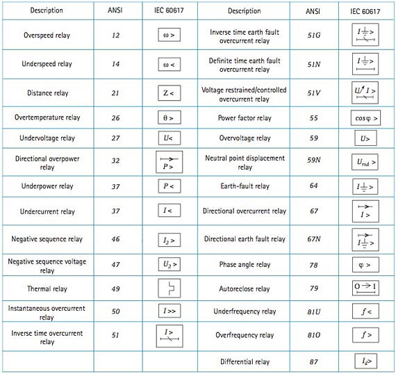
There are two methods for indicating protection relay functions in common use. One is given in ANSI Standard C37-2, and uses a numbering system for various functions. The functions are supplemented by letters where amplification of the function is required. The other is given in IEC 60617, and uses graphical symbols. To assist the Protection Engineer in converting from one system to the other, a select list of ANSI device numbers and their IEC equivalents is given in Figure A2.1.
.
Related articles

Testiranje performansi IEC 61850 GOOSE poruka
Jedan od čestih zahteva za uređaje relejne zaštite je podrška za IEC 61850 standard. U okviru standarda predviđene su i poruke za brzu razmenu informacija između releja tzv. GOOSE (Generic object-oriented substation event). U pitanju su uglavnom trip, interlocking, breaker failure i slični signali. Vreme transfera ovih signala je kritično, njihovo kašnjenje može prouzrokovati neželjeno isključenje potrošača ili oštećenje opreme.
U ovom radu istražićemo koja softverska arhitektura je najpogodnija da se ostvare tražene performanse. Softver za slanje/prijem GOOSE poruka može se nalaziti u real time (RT) ili user space prostoru operativnog sistema. Razmotrićemo user space i RT implementacije na dve različite mikroprocesorske arhitekture – ARM9 i PowerPC.
Do degradacije performansi može doći iz 2 razloga:
- Zaštitna funkcija ima najviši prioritet. Najmanje 500 μs tokom svake milisekunde GOOSE task će biti uskraćen za procesorsko vreme.
- U slučaju čiste user-space implementacije operativni sistem će prekidati GOOSE task na potpuno nedeterministički način.
User Space Test
Za testiranje performansi GOOSE poruka u user space-u razvijeno je okruženje bazirano na ARM7 arhitekturi:
- ARM7 sa integrisanim Ethernet-om za slanje, prijem i time-stampovanje poruka.
- PC aplikacija za setovanje parametara i prikupljanje rezultata.

- Slika 1. Test konfiguracija za user space test
Suština testa je sledeća: ARM7 ploča lansira niz poruka i beleži odlazno vreme za svaku poruku. ARM9 i PowerPC ploče su podešene da odmah po prijemu GOOSE poruke odgovore sa identičnom porukom sa istim rednim brojem.
ARM7 ploča registruje odgovor i pomoću rednog broja uparuje poruku sa originalnom porukom i računa proteklo vreme.

- Slika 2. Analiza vremena
Na gornjoj slici može se videti analiza utrošenog vremena. A i B su zanemarljivi. Zbog prirode testa može se precizno meriti 2C+D ali ne možemo tačno znati koliko iznose C i D pojedinačno. No, u krajnjoj liniji to i nije bitno sa stanovišta standarda. Pogledajmo rezultate testa. ARM7 ploča lansira niz GOOSE poruka u razmaku od 100ms. Rezultati se mere i prikazuju u Excel-u.
Da bi rezultat bio što realniji uključena je prekostrujna zaštita. Na Y osi prikazano je vreme u milisekundama a na X osi redni broj GOOSE poruke.
")
Slika 3. ARM9 100ms (X osa – redni broj poruke, Y osa vreme transfera)
Vidimo da tokom 20 sekundi vreme odgovora osciluje oko 2 milisekunde. Sledeći korak je bio da se uključi još nekoliko zaštitnih funkcija tako da tokom 1 milisekunde zaštita troši 700 μs. Očekivano je da pri većem opterećenju GOOSE performanse opadnu.
To se zaista i dešava kao što možemo videti na sledećoj slici:
")
Slika 4. ARM9 100ms, 700μs (X osa – redni broj poruke, Y osa vreme transfera)
Vreme sada osciluje oko 7 milisekudi. Iako je očekivano da će performanse opasti, ipak je postignuti rezultat iznad očekivanja. 7 milisekundi je i dalje dovoljno za neke aplikacije. Ovo su rezultati sa ARM9 platformu. PowerPC platforma se pokazala nešto bolje, jer ima skoro 2 puta veću procesorsku snagu. Na sledeće 2 slike vidimo rezultate.
")
Slika 5. PowerPC 100ms (X osa – redni broj poruke, Y osa vreme transfera)
")
Slika 6. PowerPC 100ms, 700μs (X osa – redni broj poruke, Y osa vreme transfera)
Pri manjem opterećenju vreme osciluje oko 0.8 ms a pri većem oko 2.5 ms. Kao što vidimo izmerena vremena se kreću u okvirima koji nude solidan dijapazon primena. Na žalost ova vremena važe samo u slučaju da je GOOSE task jedini aktivni task. U slučaju postojanja drugih taskova – na primer disturbance recorder, event recorder, embedded web server, IEC 61850 MMS server itd… vremena postaju nepredvidiva i mogu ići i do 80ms, što je naravno neprihvatljivo.
Real Time Test

Slika 7. Test konfiguracija za real time test
Mada je real time GOOSE nešto teži za implementaciju, nudi neke značajne prednosti kako ćemo videti. Test okruženje za real time je značajno drugačije. Za testiranje je korišćen mrežni analizator. Program se može besplatno skinuti sa Interneta (1). Suština testa je sledeća: zaštitni relej je podešen da osluškuje poruke koje emituje laptop računar i da momentalno odgovori sa istom vrednošću dataseta koja je u dolaznoj poruci. Kada analiziramo niz poruka u mrežnom analizatoru doći ćemo do momenta kada relej i laptop emituju identičnu vrednost.
Vreme između momenta kada laptop počinje sa emitovanjem i momenta kada relej počne da emituje istu vrednost kao i laptop je traženo vreme.
Na sledećoj slici možemo videti rezultate prikazane u mrežnom analizatoru.

Slika 8. Ethereal mrežni analizator

Slika 9. Niz GOOSE poruka sa vremenima prijema, mrežnim adresama i oznakom protokola
Poruku broj 42 emituje laptop,a poruku 43 relejna zaštita. Ako oduzmemo vremena prijema: 3,757 – 3,753 = 4msec. Pri ponovljenim merenjima rezultat osciluje oko 4ms. Razlog za to je što su taskovi za slanje i prijem podešeni da se bude na svake 2 milisekunde.
Zaključak
Na prvi pogled real time i user space implementacije operišu u sličnim vremenskim okvirima. Ali, postoji ozbiljna razlika. Kod RT implementacije GOOSE task može da deli procesor sa proizvoljnim brojem ostalih taskova kao što je disturbance recorder i sl. Takva arhitektura u mnogome smanjuje krajnju cenu uređaja i daje korisniku više funkcionalnosti. U suprotnom bi GOOSE softver morao da obitava na zasebnom hardveru.
.
AUTOR STRUČNOG TEKSTA:
Veljko Milisavljević | ABS Control Systems, Srbija
![]()
![]()
.
Related articles
10,010 views

International Standard - IEC 61850
The traditional approach to substation integration used standardized RTU protocols that were designed to provide protocol efficiency for operation over bandwidth limited serial links.
While such limitations remain for many applications, substation hardened equipment implementing modern networking standards like Ethernet now provide a cost effective means of enabling high speed communications within the substation.
To truly take advantage of this technology and dramatically lower the total cost of ownership of substation automation systems, a new approach to substation integration that goes beyond a simple RTU protocol is needed.
The recent international standard IEC 61850 proposes a unified solution of the communication aspect of substation automation. However, the standard itself is not easily understood by users other than domain experts. We present our understanding of the IEC 61850 standard as well as the design and implementation of our simulation tool in this report. Also, we give suggestions on the implementation of this standard based on our experience and lessons in the development of our simulation.
1. Introduction
Today, power substations are mostly managed by substation automation systems. These systems employ computers and domain specific applications to optimize the management of substation equipment and to enhance operation and maintenance efficiencies with minimal human intervention [8].
Once upon a time, substation automation systems utilized simple, straightforward and highly specialized communication protocols [7]. These protocols concerned less about the semantics of the exchanged data, data types of which were relatively primitive. Equipment was dumb and systems were simple. However, today’s substation automation systems can no longer enjoy such simplicity because of their growing complexity — equipment becomes more intelligent and most of those simple old systems have been gradually replaced by open systems, which embrace the advantage of emerging technology like relational database systems, multi-task operating systems and support for state-of-the-art graphical display technology.
Besides, devices from different manufacturers used different substation automation protocols [9, 3, 12], disabling them to talk to each other. Utilities have been paying enormous money and time to configure these devices to work together in a single substation. Today most utilities and device manufacturers have recognized the need for a unified international standard to support seamless cooperation among products from different vendors.
The IEC 61850 international standard, drafted by substation automation domain experts from 22 countries, seeks to tackle the aforementioned situation. This standard takes advantage of a comprehensive object-oriented data model and the Ethernet technology, bringing in great reduction of the configuration and maintenance cost. Unlike its predecessor, the Utility Communication Architecture protocol 2.0 (UCA 2.0) [12], the IEC 61850 standard is designed to be capable for domains besides substation automation. To make the new protocol less domain dependent, the standard committee endeavored to emphasize on the data semantics, carving out most of the communication details. This effort, however, could result in difficulties in understanding the standard.
In this research project, we aim to get a clear understanding of the IEC 61850 standard and simulate the protocol based on J-Sim [11]. Our ultimate goal is to investigate the security aspect about the IEC 61850 standard.
2 The IEC 61850 standard
The first release of the IEC 61850 consists of a set of documents of over 1,400 pages. These documents are divided into 10 parts, as listed in Table 1. Part 1 to Part 3 give some general ideas about the standard. Part 4 defines the project and management requirements in an IEC 61850 enabled substation. Part 5 specifies the required parameters for physical implementation. Part 6 defines an XML based language for IED configuration, presenting a formal view of the concepts in the standard. Part 7 elaborates on the logical concepts, which is further divided into four subparts (listed in Table 2). Part 8 talks about how to map the internal objects to the presentation layer and to the Ethernet link layer. Part 9 defines the mapping from sampled measurement value (SMV) to point-to-point Ethernet.
The last part gives instructions on conformance testing. Since Part 7 defines the core concepts of the IEC 61850 standard, we will focus on this part in this report.
| Subpart | Title |
| 7.1 | .Principles and Models |
| 7.2 | .Abstract Communication Service Interface |
| 7.3 | .Common Data Classes |
| 7.4 | .Compatible Logical Node Classes and Data Classes |
| Table 2: Subparts of IEC 61850-7 | |
The IEC 61850 standard is not easy to understand for people other than experts in the substation automation domain due to the complexity of the documents and the assumed domain-specific knowledge. Introductory documents on the standard abound [13, 4, 7, 5, 8, 2], but most of them are in the view of substation automation domain experts. Kostic et al. explained the difficulties they had in understanding the IEC 61850 standard [7].
In this section, we provide another experience of understanding this standard, trying to explain the major concepts of the IEC 61850 standard.
2.1 Challenges
Understanding the IEC 61850 standard proposes the following challenges for a outsider of the substation automation domain:
- As a substation automation standard proposed by a group of domain experts, the IEC 61850 protocol assumes quite an amount of domain-specific knowledge, which is hardly accessible by engineers and researchers out of the substation automation domain. To make things worse, the terms used in the standard is to some extent different from those commonly used in software engineering, bringing some difficulties for software engineers in reading the standard.
- The entire standard, except Part 6, is described in natural language with tables and pictures, which is known to be ambiguous and lack of preciseness. This situation is problematic because the IEC 61850 concepts are defined by more than 150 mutually relevant tables distributed over more than 1,000 pages. A formal presentation of all these concepts would be appreciated.
- The experts proposing this protocol come from 22 different countries and are divided into 10 working groups, each responsible to one part of the standard. Due to the different backgrounds and the informal presentation style of the standard, the standard contains a considerable number of inconsistencies. Such inconsistencies are more obvious for different parts of the standard, e.g. the data model described in Part 6 is clearly different from that described in Part 7.
- The standard committee made a great effort to describe the protocol in an object-oriented manner but the result is not so object-oriented. For example, the ACSI services are grouped by different classes, but reference to the callee object is not defined as a mandatory argument of the service function.
- The standard is designed to be implementation independent but this is not always true. For example, the data attribute TimeAccuracy in Part 7-2 Table 8 is defined as CODED ENUM, while what it virtually represents is a 5-bit unsigned integer; the frequent use of PACKED LIST (i.e. “bit fields” in the C language) also brings implementation details to interface design.
- Things are mixed up in the documents. Mandatory components and optional components are mixed in the standard, and domain independent concepts are mixed up with domain specific concepts. Even though the optional components and mandatory ones are marked with “O” and “M” alternatively, it would be a tough task to refine a model consisting only the mandatory components due to the implicit dependences between attributes in different tables and the conditional inclusion of some attributes. In fact, there are 29 common data classes and 89 compatible logical nodes defined in the standard, the relationship among which is unclear.
.
2.2 Intelligent electronic device
In the past, utility communication standards usually assumed some domain-specific background of the readers. Consequently, they contained a lot of implicit domain knowledge, which is hardly accessible to outsiders (e.g. software engineers) [7]. The IEC 61850 standard does not escape from this category. To help understanding the logical concepts of IEC 61850, we would like to lay a basic idea of intelligent electronic devices (IED), the essential physical object hosting all the logical objects.
Basically, the term intelligent electronic device refers to microprocessor-based controllers of power system equipment, which is capable to receive or send data/control from or to an external source [8]. An IED is usually equipped with one or more microprocessors, memory, possibly a hard disk and a collection of communication interfaces (e.g. USB ports, serial ports, Ethernet interfaces), which implies that it is essentially a computer as those for everyday use.
However, IEDs may contain some specific digital logics for domain-specific processing.
IEDs can be classified by their functions. Common types of IEDs include relay devices, circuit breaker controllers, recloser controllers, voltage regulators etc.. It should be noted that one IED can perform more than one functions, taking advantage of its general-purpose microprocessors. An IED may have an operating system like Linux running in it.
| Part | Title |
| 1 | .Introduction and Overview |
| 2 | .Glossary |
| 3 | .General Requirements |
| 4 | .System and Project Management |
| 5 | .Communication Requirements for Functions and Device .Models |
| 6 | .Configuration Description Language for Communication in .Electronic Substations Related to IEDs |
| 7 | .Basic Communication Structure for Substation and Feeder .Equipment |
| 8 | .Specific Communication Service Mapping (to MMS and to .Ethernet) |
| 9 | .Specific Communication Service Mapping (from Sampled .Values) |
| 10 | .Conformance Testing |
| Table 1: Parts of the IEC 61850 standard documents | |
2.3 Substation architecture
A typical substation architecture is shown in Figure 1. The substation network is connected to the outside wide area network via a secure gateway. Outside remote operators and control centers can use the abstract communication service interface (ACSI) defined in Part 7-2 to query and control devices in the substation. There is one or more substation buses connecting all the IEDs inside a substation. A substation bus is realized as a medium bandwidth Ethernet network, which carries all ACSI requests/responses and generic substation events messages (GSE, including GOOSE and GSSE).
There is another kind of bus called process bus for communication inside each bay. A process bus connects the IEDs to the traditional dumb devices (merge units, etc.) and is realized as a high bandwidth Ethernet network. A substation usually has only one global substation bus but multiple process buses, one for each bay.

Figure 1: Substation architecture
ACSI requests/responses, GSE messges and sampled analog values are the three major kinds of data active in the substation network. Since we are less interested in communication on the process buses (like sampled value multicasting), we focus on the activities on the substation bus in this report, especially the ACSI activities.
Interactions inside a substation automation system mainly fall into three categories: data gathering/setting, data monitoring/reporting and event logging.
The former two kinds of interactions are the most important — in the IEC 61850 standard all inquiries and control activities towards physical devices are modeled as getting or setting the values of the corresponding data attributes, while data monitoring/reporting provides an efficient way to track the system status, so that control commands can be issued in a timely manner.
To realize the above kinds of interaction, the IEC 61850 standard defines a relatively complicated communication structure, as is shown in Figure 2.

Figure 2: The communication profiles
Five kinds of communication profiles are defined in the standard: the abstract communication service interface profile (ACSI), the generic object oriented substation event profile (GOOSE), the generic substation status event profile (GSSE), the sampled measured value multicast profile (SMV), and the time synchronization profile. ACSI services enable client-server style interaction between applications and servers.
GOOSE provides a fast way of data exchange on the substation bus and GSSE provides an express way of substation level status exchange. Sample measured value multicast provides an effective way to exchange data on a process bus.
.
2.4 Abstract communication service interface
ACSI is the primary interface in the IEC 61850 standard not only because it is the interface via which applications talk with servers, but also in the sense that the ACSI communication channel is an important part of a logical connection between two logical nodes. ACSI defines the semantics of the data exchanged between applications and servers, thus it becomes the major part of the IEC 61850 standard.
The standard committee adopt an object-oriented approach in the design of ACSI, which includes a hierarchical and comprehensive data model and a set of available services for each class in this data model. Although the data model is usually described outside the scope of the ACSI, it is actually part of it. The benefits of using an object-oriented utility communication interface are two fold. On the one hand, objects (e.g. registers) can be referenced in an intuitive way (e.g. “Relay0/MMXU0.voltage”) instead of by the traditional physical address (like Reg#02432). On the other hand, software engineers can build more reliable applications using such service interface.
In the following two sections, we present a brief description on these two ACSI components.
.
2.5 Data model
The hierarchical data model defined in the IEC 61850 is depicted in Figure 3 and Figure 4.
Server is the topmost component in this hierarchy. It serves as the joint point of physical devices and logical objects. Theoretically one IED may host one or more server instances, but in practice usually only one server instance runs in an IED. A server instance is basically a program running in an IED, which shares the same meaning with other servers like FTP server etc.. Each server has one or more access points, which are the logical representation of a NIC. When a client is to access data or service of the server, it should connect to an access point of this server and establish a valid association.
Each server hosts several files or logical devices. Clients can manipulate files in the server like talking to a FTP server, which is usually used as a means to upload/update the configuration file of an IED. A logical device is the logical correspondence of a physical device. It is basically a group of logical nodes performing similar functions.
Functions supported by an IED are conceptually represented by a collection of primitive, atomic functional building blocks called logical nodes.
The IEC 61850 standard predefines a collection of template logical nodes (i.e. compatible logical nodes) in Part 7-4. Besides the regular logical nodes for functions, the standard also requires every logical device have two specific logical nodes: Logical Node Zero (LN0) and LPHD, which correspond to the logical device and the physical device, alternatively. Besides holding status information of the logical device, LN0 also provides additional functions like setting-group control, GSE control, sampled value control etc..
In the IEC 61850 standard, the entire substation system is modeled as a distributed system consisting of a collection of interacting logical nodes, which are logically connected by logical connections. It should be noted that the term logical connection refers to the logical concept of the connections between two logical nodes, which can be direct or indirect or even a combination of many different kinds of communication channels. In fact, the connection of two logical nodes is usually both indirect and a combination of TCP, UDP and direct Ethernet connections. We will explain logical connections in Section 2.9 (next article).
Data exchanged between logical nodes are modeled as data objects. A logical node usually contains several data objects. Each data object is an instance of the DATA class and has a common data class type.

Figure 3: Hierarchy of the IEC 61850 data model
Similar to the concept of objects in most object-oriented programming languages, a data object consists of many data attributes, which are instances of data attributes of the corresponding common data class. Data attributes are typed and restricted by some functional constraints. Instead of grouping data attributes by data objects, functional constraints provide a way to organize all the data attributes in a logical node by functions. Types of data attributes can be either basic or composite.
Basic types are primitive types in many programming languages, whereas composite types are composition of a collection of primitive types or composite types.
In the IEC 61850 standard, data attributes are at least as important as, if not more than, data objects for two reasons.

Figure 4: The data model of the IEC 61850
Firstly, data objects are just logical collections of the contained data attributes while (primitive) data attributes are the de facto logical correspondence to the physical entities (memory units, registers, communication ports, etc.); secondly, the purpose of data objects is for the convenience of managing and exchanging values of a group of data attributes sharing the same function.
Despite data objects, the IEC 61850 standard provides the concept of data set as another ways to manage and exchange a group of data attributes. Members of a data set can be data objects or data attributes. The concept of data set is somewhat similar to the concept of view in the area of database management systems.
In the IEC 61850 standard, most services involve data sets. Members in a data set unnecessarily come from the same logical node or the same data object, thus providing high flexibility of data management. Data sets are categorized into permanent ones and temporary ones.
Permanent data sets are hosted by logical nodes and will not be automatically deleted unless on the owners’ explicit requests; temporary data sets are exclusively hosted by the association having created them and will be automatically deleted when the association ends.
To be continued soon in next article: IEC 61850 in details (2)
SOURCE:
- Understanding and Simulating the IEC 61850 Standard by Yingyi Liang & Roy H. Campbell, Department of Computer Science University of Illinois at Urbana-Champaign
.
Related articles
61,935 views

ANSI Functions For Protection Devices
In the design of electrical power systems, the ANSI Standard Device Numbers denote what features a protective device supports (such as a relay or circuit breaker). These types of devices protect electrical systems and components from damage when an unwanted event occurs, such as an electrical fault.
ANSI numbers are used to identify the functions of meduim voltage microprocessor devices.
ANSI facilitates the development of American National Standards (ANS) by accrediting the procedures of standards developing organizations (SDOs). These groups work cooperatively to develop voluntary national consensus standards. Accreditation by ANSI signifies that the procedures used by the standards body in connection with the development of American National Standards meet the Institute’s essential requirements for openness, balance, consensus and due process.
Current protection functions
ANSI 50/51 – Phase overcurrent
Three-phase protection against overloads and phase-to-phase short-circuits.
ANSI index ↑
ANSI 50N/51N or 50G/51G – Earth fault
Earth fault protection based on measured or calculated residual current values:
- ANSI 50N/51N: residual current calculated or measured by 3 phase current sensors
- ANSI 50G/51G: residual current measured directly by a specific sensor
ANSI 50BF – Breaker failure
If a breaker fails to be triggered by a tripping order, as detected by the non-extinction of the fault current, this backup protection sends a tripping order to the upstream or adjacent breakers.
ANSI index ↑
ANSI 46 – Negative sequence / unbalance
Protection against phase unbalance, detected by the measurement of negative sequence current:
- sensitive protection to detect 2-phase faults at the ends of long lines
- protection of equipment against temperature build-up, caused by an unbalanced power supply, phase inversion or loss of phase, and against phase current unbalance
ANSI 49RMS – Thermal overload
Protection against thermal damage caused by overloads on machines (transformers, motors or generators).
The thermal capacity used is calculated according to a mathematical model which takes into account:
- current RMS values
- ambient temperature
- negative sequence current, a cause of motor rotor temperature rise
Recloser
ANSI 79
Automation device used to limit down time after tripping due to transient or semipermanent faults on overhead lines. The recloser orders automatic reclosing of the breaking device after the time delay required to restore the insulation has elapsed. Recloser operation is easy to adapt for different operating modes by parameter setting.
ANSI index ↑
Directional current protection
ANSI 67N/67NC type 1
ANSI 67 – Directional phase overcurrent
Phase-to-phase short-circuit protection, with selective tripping according to fault current direction. It comprises a phase overcurrent function associated with direction detection, and picks up if the phase overcurrent function in the chosen direction (line or busbar) is activated for at least one of the 3 phases.
ANSI index ↑
ANSI 67N/67NC – Directional earth fault
Earth fault protection, with selective tripping according to fault current direction.
3 types of operation:
- type 1: the protection function uses the projection of the I0 vector
- type 2: the protection function uses the I0 vector magnitude with half-plane tripping zone
- type 3: the protection function uses the I0 vector magnitude with angular sector tripping zone
ANSI 67N/67NC type 1
Directional earth fault protection for impedant, isolated or compensated neutralsystems, based on the projection of measured residual current.
ANSI index ↑
ANSI 67N/67NC type 2
Directional overcurrent protection for impedance and solidly earthed systems, based on measured or calculated residual current. It comprises an earth fault function associated with direction detection, and picks up if the earth fault function in the chosen direction (line or busbar) is activated.
ANSI index ↑
ANSI 67N/67NC type 3
Directional overcurrent protection for distribution networks in which the neutral earthing system varies according to the operating mode, based on measured residual current. It comprises an earth fault function associated with direction detection (angular sector tripping zone defined by 2 adjustable angles), and picks up if the earth fault function in the chosen direction (line or busbar) is activated.
ANSI index ↑
Directional power protection functions
ANSI 32P – Directional active overpower
Two-way protection based on calculated active power, for the following applications:
- active overpower protection to detect overloads and allow load shedding
- reverse active power protection:
- against generators running like motors when the generators consume active power
- against motors running like generators when the motors supply active power
ANSI 32Q/40 – Directional reactive overpower
Two-way protection based on calculated reactive power to detect field loss on synchronous machines:
- reactive overpower protection for motors which consume more reactive power with field loss
- reverse reactive overpower protection for generators which consume reactive power with field loss.
Machine protection functions
ANSI 37 – Phase undercurrent
Protection of pumps against the consequences of a loss of priming by the detection of motor no-load operation.
It is sensitive to a minimum of current in phase 1, remains stable during breaker tripping and may be inhibited by a logic input.
ANSI index ↑
ANSI 48/51LR/14 – Locked rotor / excessive starting time
Protection of motors against overheating caused by:
- excessive motor starting time due to overloads (e.g. conveyor) or insufficient supply voltage.
The reacceleration of a motor that is not shut down, indicated by a logic input, may be considered as starting. - locked rotor due to motor load (e.g. crusher):
- in normal operation, after a normal start
- directly upon starting, before the detection of excessive starting time, with detection of locked rotor by a zero speed detector connected to a logic input, or by the underspeed function.
ANSI 66 – Starts per hour
Protection against motor overheating caused by:
- too frequent starts: motor energizing is inhibited when the maximum allowable number of starts is reached, after counting of:
- starts per hour (or adjustable period)
- consecutive motor hot or cold starts (reacceleration of a motor that is not shut down, indicated by a logic input, may be counted as a start)
- starts too close together in time: motor re-energizing after a shutdown is only allowed after an adjustable waiting time.
ANSI 50V/51V – Voltage-restrained overcurrent
Phase-to-phase short-circuit protection, for generators. The current tripping set point is voltage-adjusted in order to be sensitive to faults close to the generator which cause voltage drops and lowers the short-circuit current.
ANSI index ↑
ANSI 26/63 – Thermostat/Buchholz
Protection of transformers against temperature rise and internal faults via logic inputs linked to devices integrated in the transformer.
ANSI index ↑
ANSI 38/49T – Temperature monitoring
Protection that detects abnormal temperature build-up by measuring the temperature inside equipment fitted with sensors:
- transformer: protection of primary and secondary windings
- motor and generator: protection of stator windings and bearings.
Voltage protection functions
ANSI 27D – Positive sequence undervoltage
Protection of motors against faulty operation due to insufficient or unbalanced network voltage, and detection of reverse rotation direction.
ANSI index ↑
ANSI 27R – Remanent undervoltage
Protection used to check that remanent voltage sustained by rotating machines has been cleared before allowing the busbar supplying the machines to be re-energized, to avoid electrical and mechanical transients.
ANSI index ↑
ANSI 27 – Undervoltage
Protection of motors against voltage sags or detection of abnormally low network voltage to trigger automatic load shedding or source transfer.
Works with phase-to-phase voltage.
ANSI index ↑
ANSI 59 – Overvoltage
Detection of abnormally high network voltage or checking for sufficient voltage to enable source transfer. Works with phase-to-phase or phase-to-neutral voltage, each voltage being monitored separately.
ANSI index ↑
ANSI 59N – Neutral voltage displacement
Detection of insulation faults by measuring residual voltage in isolated neutral systems.
ANSI index ↑
ANSI 47 – Negative sequence overvoltage
Protection against phase unbalance resulting from phase inversion, unbalanced supply or distant fault, detected by the measurement of negative sequence voltage.
ANSI index ↑
Frequency protection functions
ANSI 81H – Overfrequency
Detection of abnormally high frequency compared to the rated frequency, to monitor power supply quality.
ANSI index ↑
ANSI 81L – Underfrequency
Detection of abnormally low frequency compared to the rated frequency, to monitor power supply quality. The protection may be used for overall tripping or load shedding. Protection stability is ensured in the event of the loss of the main source and presence of remanent voltage by a restraint in the event of a continuous decrease of the frequency, which is activated by parameter setting.
ANSI index ↑
ANSI 81R – Rate of change of frequency
Protection function used for fast disconnection of a generator or load shedding control. Based on the calculation of the frequency variation, it is insensitive to transient voltage disturbances and therefore more stable than a phase-shift protection function.
Disconnection
In installations with autonomous production means connected to a utility, the “rate of change of frequency” protection function is used to detect loss of the main system in view of opening the incoming circuit breaker to:
- protect the generators from a reconnection without checking synchronization
- avoid supplying loads outside the installation.
Load shedding
The “rate of change of frequency” protection function is used for load shedding in combination with the underfrequency protection to:
- either accelerate shedding in the event of a large overload
- or inhibit shedding following a sudden drop in frequency due to a problem that should not be solved by shedding.
Related book: Relay selection guide
Link: Register
Autor: Edvard Csanyi, CsanyiGroup
.
Related articles
5,747 views
![]() Principi IEC standarda IEC 60364 i 60479-1 predstavljaju osnove na kome počiva većina električnih standarda u svetu. Dole su prikazani oni najvažniji. Više o ostalim standardima – klikni ovde.
Principi IEC standarda IEC 60364 i 60479-1 predstavljaju osnove na kome počiva većina električnih standarda u svetu. Dole su prikazani oni najvažniji. Više o ostalim standardima – klikni ovde.
IEC 60364-1 Electrical installations of buildings – Fundamental principles
IEC 60364-4-41 Electrical installations of buildings – Protection for safety – Protection against electric shock
IEC 60364-4-42 Electrical installations of buildings – Protection for safety – Protection against thermal effects
IEC 60364-4-43 Electrical installations of buildings – Protection for safety – Protection against overcurrent
IEC 60364-4-44 Electrical installations of buildings – Protection for safety – Protection against electromagnetic and voltage disrurbance
IEC 60364-5-51 Electrical installations of buildings – Selection and erection of electrical equipment – Common rules
IEC 60364-5-52 Electrical installations of buildings – Selection and erection of electrical equipment – Wiring systems
IEC 60364-5-53 Electrical installations of buildings – Selection and erection of electrical equipment – Isolation, switching and control
IEC 60364-5-54 Electrical installations of buildings – Selection and erection of electrical equipment – Earthing arrangements
IEC 60364-5-55 Electrical installations of buildings – Selection and erection of electrical equipment – Other equipments
IEC 60364-6-61 Electrical installations of buildings – Verification and testing – Initial verification
IEC 60364-7-701 Electrical installations of buildings – Requirements for special installations or locations – Locations containing a bath tub or shower basin
IEC 60364-7-702 Electrical installations of buildings – Requirements for special installations or locations – Swimming pools and other basins
IEC 60364-7-703 Electrical installations of buildings – Requirements for special installations or locations – Locations containing sauna heaters
IEC 60364-7-704 Electrical installations of buildings – Requirements for special installations or locations – Construction and demolition site installations
IEC 60364-7-705 Electrical installations of buildings – Requirements for special installations or locations – Electrical installations of agricultural and horticultural
premises
IEC 60364-7-706 Electrical installations of buildings – Requirements for special installations or locations – Restrictive conducting locations
IEC 60364-7-707 Electrical installations of buildings – Requirements for special installations or locations – Earthing requirements for the installation of data
processing equipment
IEC 60364-7-708 Electrical installations of buildings – Requirements for special installations or locations – Electrical installations in caravan parks and caravans
IEC 60364-7-709 Electrical installations of buildings – Requirements for special installations or locations – Marinas and pleasure craft
IEC 60364-7-710 Electrical installations of buildings – Requirements for special installations or locations – Medical locations
IEC 60364-7-711 Electrical installations of buildings – Requirements for special installations or locations – Exhibitions, shows and stands
IEC 60364-7-712 Electrical installations of buildings – Requirements for special installations or locations – Solar photovoltaic (PV) power supply systems
IEC 60364-7-713 Electrical installations of buildings – Requirements for special installations or locations – Furniture
IEC 60364-7-714 Electrical installations of buildings – Requirements for special installations or locations – External lighting installations
IEC 60364-7-715 Electrical installations of buildings – Requirements for special installations or locations – Extra-low-voltage lighting installations
IEC 60364-7-717 Electrical installations of buildings – Requirements for special installations or locations – Mobile or transportable units
IEC 60364-7-740 Electrical installations of buildings – Requirements for special installations or locations – Temporary electrical installations for structures,
amusement devices and booths at fairgrounds, amusement parks and circuses
IEC 60427 High-voltage alternating current circuit-breakers
IEC 60439-1 Low-voltage switchgear and controlgear assemblies – Type-tested and partially type-tested assemblies
IEC 60439-2 Low-voltage switchgear and controlgear assemblies – Particular requirements for busbar trunking systems (busways)
IEC 60439-3 Low-voltage switchgear and controlgear assemblies – Particular requirements for low-voltage switchgear and controlgear assemblies intended to
be installed in places where unskilled persons have access for their use – Distribution boards
IEC 60439-4 Low-voltage switchgear and controlgear assemblies – Particular requirements for assemblies for construction sites (ACS)
Read more


