

Proračun pada napona
Voltage drop is the reduction in voltage in an electrical circuit between the source and load. In electrical wiring national and local electrical codes may set guidelines for maximum voltage drop allowed in a circuit, to ensure reasonable efficiency of distribution and proper operation of electrical equipment (the maximum permitted voltage drop varies from one country to another)[1].
Voltage drop may be neglected when the impedance of the interconnecting conductors is small relative to the other components of the circuit.
.
Related articles
3,064 views
Book with graphical explanations of short circuit and its calculations (purpose, standards, types, calculations…)
.
Related articles
- Siemens MV Topic – Loss Of Vacuum
- Arc-resistant low voltage switchgear
- Standard IEC 60947-2
- Connecting Wind Turbines To The Power Grid
- Paralleling Three-Phase Transformers
Unburied cables:
.
Related articles
1,823 views
What is cascading?
Cascading is the use of the current limiting capacity of circuit breakers at a given point to permit installation of lower-rated and therefore lower-cost circuit breakers downstream. The upstream circuit breakers acts as a barrier against short-circuit currents. In this way, downstream circuit breakers with lower breaking capacities than the prospective short-circuit (at their point of installation) operate under their normal breaking conditions. Since the current is limited throughout the circuit controlled by the limiting circuit breaker, ascading applies to all switchgear downstream. It is not restricted to two consecutive devices.
General use of cascadingcom
With cascading, the devices can be installed in different switchboards. Thus, in general, cascading refers to any combination of circuit breakers where a circuit breaker with a breaking capacity less than the prospective Isc at its point of installation can be used. Of course, the breaking capacity of the upstream circuit breaker must be greater than or equal to the prospective short-circuit current at its point of installation.
The combination of two circuit breakers in cascading configuration is covered by the following standards:
- IEC 60947-2 (construction)
- NF C 15-100, § 434.3.1 (installation)
Coordination between circuit breakers
The use of a protective device possessing a breaking capacity less than the prospective short-circuit current at its installation point is permitted as long as another device is installed upstream with at least the necessary breaking capacity. In this case, the characteristics of the two devices must be coordinated in such a way that the energy let through by the upstream device is not more than that which can be withstood by the downstream device and the cables protected by these devices without damage.
Cascading can only be checked by laboratory tests and the possible combinations can be specified only by the circuit breaker manufacturer.
Cascading and protection discrimination
In cascading configurations, due to the Roto-active breaking technique, discrimination is maintained and in some cases, even enhanced.
.
Related articles
- Standard IEC 60947-2
- ABB launches new generation 420kV gas insulated switchgear
- GE AKD-20 Low-Voltage Switchgear
- Maintenance Of SF6 Gas Circuit Breakers
- Siemens MV Topic – Loss Of Vacuum
1,511 views
 Da li ste ikad napisali (i objavili) svoj stručni tekst koji je puno pomogao i Vama i drugima? Ili ste možda savetima pomogli drugima, a nikada napisali isto? O čemu se radi? U cilju poboljšanja stručnog sadržaja websajta, ideja je da svako ko želi da pomogne tu ideju – pošalje svoj stručni tekst (autorski tekst), iskustvo ili savete, i prilikom objavljivanja bude potpisnik teksta – afirmišući sebe na taj način.
Naravno, pošto je tematika ovog websajta isključivo energetika, automatika, projektovanje električnih instalacija, izvođenje i sl., stručni (autorski) tekstovi bi bili iz ove oblasti. Izbor teme za stručni tekst (u okvirima tematike websajta) nije ničim ograničen. Može se odnositi na teoriju, iskustvo u praksi, izvođenje elektroradova, zanimljivih detalja konkretnih projekata, neobičnih rešenja konkretnih problema, i slično.
Takođe tema za stručni tekst može biti i tema koju ste imali za diplomski rad ili nešto slično.
Nemate posao?
Naš websajt ima preko 2300 poseta mesečno sa konstantnim rastom i sve boljom vidljivošću na Google-u. Objavljivanjem svog stručnog teksta možete lako zapasti za oko poslodavcu koji je surfovanjem po internetu slučajno po ključnim rečima sleteo baš na stranicu sa Vašim stručnim tekstom, i zainteresovao se čoveka baš takvog profila i entuzijazma. Iskoristite šansu, ako ništa drugo, besplatno je!
Websajt www.csanyigroup.com je veoma posećen na teritoriji Srbije, BiH, Crne Gore, Hrvatske, Makedonije i Slovenije.
Ukoliko ste zainteresovani, email sa stručnim tekstom možete poslati na našu email adresu: office@csanyigroup.com. Obavezno pošaljite svoje podatke kako bi bili potpisani ispod teksta. Ukoliko imate nalog na LinkedIn, ili nekom sličnom websajtu, možete poslati link ka svom profilu.
Sam tekst može biti pisan u sledećim formatima: TXT, RTF, DOC i DOCX. Stručni tekst može sadržati i slike. Sav sadržaj iz dokumenta će biti identično prenet u post koji će biti objavljen na našem websajtu www.csanyigroup.com.
Stručni tekst će biti objavljen pod kategorijom Stručni tekstovi, i to par sati nakon što pošaljete tekst. Svaki objavljeni autorski tekst će imati svoj permalink (permanentni link) koji će autor moći da koristi (linkuje) na drugim websajtovima.
1,320 views
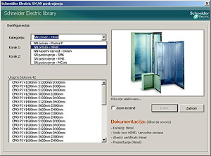 U septembru će biti objavljena brendirana verzija ePlusMenuCAD-a od strane Schneider Electric-a Srbija. Skoro svi NN i SN razvodni ormani će biti okupljeni na jednom mestu: Prisma P, Himel, OKKEN kasetni razvod, SM6, RM6 i MCset.
U biblioteku simbola će biti uključeni prednji izgledi ormana, tj. polja, pogledi odozgo sa otvorima za kablove, kao i tehnički crteži pojedinih tipova ormana. OKKEN kasetni razvod će biti kompletan, što znači da će sadržati pored simbola, tj. blokova polja, imati i elektropremu u kasetama i fiksnim delovima polja. SN postrojenja će imati prednje izglede po tipovima polja, kao i jednopolne šeme za svako polje posebno. Naravno svi simboli i šeme od polja će moći da se edituju posle insertovanja.
Dakle, izrada dela projekta prednjih izgleda postrojenja i konkretnih ormana sa elektroopremom će biti umnogome olakšana sa ovom bazom simbola.
ePlusMenuCAD SCH će biti u DVD izdanju, jer će pored simbola ormana i postrojenja imati i za svaki tip ormana i najnoviji katalog u PDF formatu, uputstvo za rukovanje, razne prezentacije, kao i ateste i sertifikate. Za pojedine tipove postrojenja biće dostupan i dodatni softver (za proračun hlađenja…). Svi pomenuti katalozi, prezentacije, softver i ostali dokumenti u PDF formatu će se otvarati direktno iz AutoCAD-a u kome je instaliran ePlusMenuCAD.
Još samo da dodam da je ova verzija ePlusMenuCAD-a praktično upgrade-ovana 8.5.3 verzija, samo sa dodatom bazom opreme Schneider Electric-a (oko 1100 simbola), i još nekim stvarima.
916 views
ABB Oil Gas production Hand Book
.
Related articles
- Comparison Between Vacuum and SF6 Circuit Breaker
- ABB launches new generation 420kV gas insulated switchgear
- ABB Power Transformers – A guide to manufacturing
- Cost benefits of AC drives
- ABB Feeder Protection REF615 ANSI
2,877 views

knjige sa faksa
Na stranici Sa faksa je postavljen set od 21 knjige iz oblasti energetike i pogona. Knjige, mahom skripte su potekle od studenata koji su pratili predavanja naših poznatih profesora sa ETF-a, VETŠ-a i drugih fakulteta i preneli sve u elektronsku formu. Sve knjige su na srpskom/hrvatskom jeziku, i u PDF formatu, i kao i sve ostale knjige na našem websajtu besplatne, potrebno je samo da se registrujete. Ukoliko ste registrovani korisnik, posetite Forum na kome možete otvoriti novu temu ili diskutovati sa ostalim članovima o stručnim knjigama iz energetike, automatike i drugih sličnih oblasti.
Spisak novo-postavljenih kniga:
01. Asihrone mašine
02. Električna postrojenja III
03. Električna vuča
04. Električne instalacije i osvetljenja II
05. Elektroenergetika
06. Elektroenergetski pretvarači
07. Elektrotehnika
08. Energetska elektronika
09. Ispitivanje asihronih mašina
10. Ispitivanje mašina jednosmerne struje
11. Ispitivanje sinhronih mašina
12. Ispitivanje transformatora
13. Strojarski prirucnik
14. Mašine jednosmerne struje
15. Električni materijali
16. Merenje električnih veličina
17. Merenje neelektričnih veličina
18. Opšta teorija elektrićnih mašina
19. Osnove elektronike
20. Sinhrone mašine
21. Transformatori
907 views
Na našem websajtu je definitivno nedostajao forum na kome će korisnici ePlusMenuCAD-a i ostali korisnici moći da razmenjuju svoja mišljenja, postavljaju teme i pitanja. To je sada rešeno, jer je otvoren FORUM, na kome (ukoliko ste registrovani) možete postavljati nove teme, pitanja i komunicirati sa ostalim članovima websajta. Teme foruma su ograničene na rad i korišćenje ePlusMenuCAD-a, kao i na stručne knjige, projektnu dokumentaciju i stručne programe za projektovanje električnih instalacija.
Dakle, dobrodošli na forum!
453 views
 Veliki popust od 30% na novu verziju ePlusMenuCAD-a važi do 21.juna! Ne propustite priliku da po povoljnim uslovima kupite sofisticirani alat za projektovanje električnih instalacija u okruženju AutoCAD-a.
U novoj verziji je podržana instalacija i korišćenje u AutoCAD-u 2010, a takođe su implementirane i brojne izmene koje se tiču brzine u radu. Detalje pogledajte ovde.
Ukoliko ste zainteresovani da kupite licencu, to možete učiniti ovde. Zainteresovanim korisnicima za više licenci (npr. više od 3 licence za projektni biro) odobravamo specijalne popuste. Za više informacija o popustima kontaktirajte nas na e-mail office[et]csanyigroup.com.
787 views
 Objavljena je nova verzija ePlusMenuCAD v8.5.3. Pored dosta poboljšanja kao i uslišenih molbi korisnika, CsanyiGroup nudi svojim korisnicima čak 30% popust u prvih 14 dana od dana objavljivanja nove verzije, tačnije popust važi do 21.6.2009. Super prilika da kupite program za projektovanje električnih instalacija po veoma povoljim uslovima. Korisnici ePlusMenuCAD-a koji već poseduju licencu, na ovaj popust imaju i 60% popusta kao već registrovani korisnici programa.
7,984 views
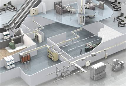 Schneider Electric u svojoj širokoj ponudi opreme za trafo stanice i objekte ima i oklopljeni šinski razvod “CANALIS” širokog dijapazona nazivnih struja, od 20A do 5000A. Za veće nazivne struje od 800A do 5000A koristi se Canalis oznake KT (postoje 2 verzije KTA i KTC). Skoro da nema projektanta koji nije čuo za Canalis, jer generalno u Srbiji investitori se odlučuju ili za kvalitetno tehničko rešenje sa Canalis-om, ili obično rešenje sa bakarnim sabirnicama. Šta je toliko specifično kod Canalis-a? Prvenstveno visoke perfomanse distribucije električne energije i jednostavno prilagođavanje potrebama aplikacije, ali o tome više u nastavku posta. Schneider Electric je u toku prethodnih godina realizovao dosta značajnih projekata u kome je figurisao Canalis šinski razvod. Neki od najvećih projekata u Srbiji i Crnoj Gori:
UŠĆE SHOPPING CENTAR | DELTA CITY BGD | DELTA CITY PG | TELENOR BUILDING | VLASINSKE HE | DRENIK ND | TENT-B | KBC NOVI SAD | TS VEKTRA | TOPLANA KONJARNIK BGD
.
Tehnički detalji KTA:
 • 8 nazivnih struja od 800A do 4000 A.
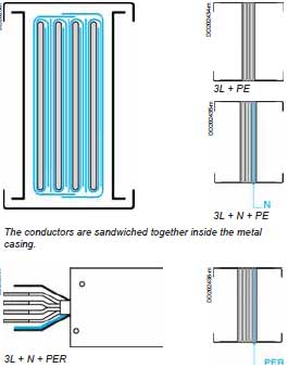
• 4 aluminijumska provodnika sa istim poprečnim presekom (verzija 3L + N + PE).
• Provodnici izolovani poliesterskim filmom, klase B 130 °C, “halogen free”.
• Standardni stepen zaštite je IP55.
• Napon izolacije: 1000 V.
• Dostupni polariteti: 3L + PE, 3L + N +PE, 3L + N + PER (ojačan provodnik PE)
• Canalis KTA je veoma kompaktan i može biti postavljen pljoštimice, nasatice ili vertikalno. To znači da može biti montiran kroz spratni podest ili protivpožarni zid bez ikakvog dodatnog protivpožarnog elementa. Standardnim rešenjem oklopljeni šinski razvod Canalis KTA može da izdrži požar 2 sata, i to u skladu sa propisom ISO 834.
Kućište koje je u boji RAL 9001 obezbeđuje odličnu zaštitu i veoma jednostavno fiksiranje, a koristi se kao PE zaštitni provodnik (u skladu sa propisom NFC 15100 i IEC 60367). U verziji sa ojačanim zaštitnim provodnikom 3L + N + PER, praktično je dodat još jedan provodnik, tj. šina čiji je poprečni presek jednak polovini preseka faznog provodnika. Ova verzija Canalis-a ima lateralno ojačanje zbog velikih struja kratkih spojeva (Isc), što ima za posledicu i oko 25% veću težinu u odnosu na standardnu verziju.
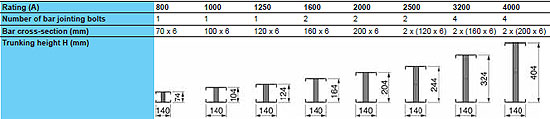
TEHNIČKE KARAKTERISTIKE CANALIS-A: Klikni na sliku da vidiš uvećano
Vrednosti nominalnih struja u gornjoj tabeli se odnosi na KTA verziju Canalis-a. Vrednosti KTC Canalisa (bakarne sabirnice) su za stepen više, i poprečni presek im je manji.
.
.
.
Gde se koristi Canalis KTA?
Osnovna namena je u trafo-stanicama za distribuciju el. energije od transformatora do niskonaponskog ormana, tj. 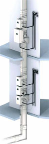 dovodnog prekidača u njemu, zatim za dalju distribuciju od NN ormana do nekog podrazvodnog ormana (u TS ili u objektu), ili i za međuveze između sekcija u NN ormanu ili više njih. Što se tiče razvoda u objektu, može se koristiti vertikalni i horizontalni razvod sa mogućnošću postavljanja dovoljnog broja otcepnih kutija (osiguračima, rastavljačima ili prekidačima do 1000A) za dalje napajanje potrošača ili podrazvoda. Vertikalna trasa se fiksira pomoću specijalnih nosača-konzola koje imaju amortizere na sebi koji služe za ublažavanje eventualnih potresa usled dilatacije zgrade ili zemljotresa.
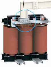
Canalis se može priključiti na bilo koji transformator, suvi ili uljni. Izvesnu prednost ima suvi transformator Schneider Electric-a – tip “TRIHAL“, koji oma mogućnost ugradnje dodatnog specijalnog priključka na Canalis (canalis interface), čime se sam spoj dodatno obezbeđuje i u električnom i mehaničkom smislu. Kod ostalih tipova (proizvođača) suvih transformatora postoji element “ruka” kojim se vrši priključenje na faze i nulu transformatora. Ovaj spoj Trihal-Canalis je već uveliko u upotrebi u puno trafo-stanica u Srbiji i Crnoj Gori, i investitori se uglavnom odlučuju na ovo rešenje zbog najveće pouzdanosti.
Što se tiče priključenja na niskonaponski orman, Canalis ima mogućnost priključenja na bilo koji orman na bilo koje mesto! Šta to znači? Znači da se šinski razvod može prilagoditi zahtevima dispozicije u TS-i, ali i zahtevima projektanta. Najstandardnije rešenje priključka jeste sa gornje ili sa donje strane ormana. Za sve tipove ormana postoji univerzalni priključak koji se koristi u tu svrhu, ali i za priključenje na uljni transformator. Priključni element se kod NN ormana naslanja na krov ili dno ormana, i sa šinama priključuje na dovodne kontakte prekidača, ili na sabirnički sistem.
Schneider Electric kao i kod transformatora, nudi i kod niskonaponakih ormana predefinisani priključak na Canalis. U pitanju su razvodni ormani PRISMA P i kasetni razvod OKKEN. Prvi tip ormana se koristi kako u trafo-stanicama, tako i u objektu kao čisto razvodni ormani. Kod nas je veoma poznat i prihvaćen zbog svoje modularnosti i jednostavnosti montaže. OKKEN se za razliku od PRISMA P ormana koristi u “teškoj” industriji, kao i kod objekata gde ne sme biti prekida napajanja, i gde se ispad izvoda rešava brzom i jednostavnom zamenom kasete. No, malo sam se udaljio od osnovne teme… Ova dva tipa ormana imaju predefinisani priključak (canalis interfase) na Canalis koji nudi veoma dobre perfomanse spoja na 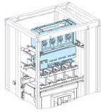 dovodni prekidač (Masterpact). U najčešćem slučaju Canalis interface se montira u gornjem delu ormana iznad prekidača. U retkim slučajevima, Canalis interface se može okrenuti i “naopačke”, kada je potrebno da Canalis dođe sa donje strane. Generalno gledano, Canalis interface je “najčistiji” način priključenja na Canalis sa najmanjim rizikom u električnom i mehaničkom smislu.
Može li se Canalis interface koristiti na drugim ormanima, koji nisu proizvodnje Schneider Electric?? Naravno da može, ali drugi ormani nemaju gotove nosače interface-a kao Prisma P i OKKEN! No, to i nije neki problem da se napravi, svaki malo veštiji panel-builder se može snaći sa prilagođavanjem interface-a.
Radeći u Schneider Electric-u do sada sam imao dosta velikih kompleksnih projekata u kome sam projektovao oklopljeni šinski razvod Canalis, i moram priznati da se svaki projekat završio na veliko zadovoljstvo krajnjeg kupca, 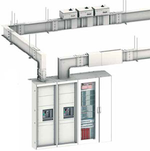 tj. investitora. Sam Canalis se inače projektuje u 3D programu u okviru AutoCAD-a, i potrebno je dosta truda i saradnje kako sa projektantom, tako i sa panel-builder-om koji proizvodi razvodne ormane na koji se priključuje Canalis, ali i sa izvođačem radova na objektu koji je u obavezi da montira Canalis.
Izvođeč radova dobija od mene iskotirane crteže sa svim detaljima. Schneider Electric uz oklopljeni šinski razvod Canalis uvek pruža i tehničku podršku izvođaču sa čime se ne može pohvaliti baš svaki proizvođač opreme.
Na kraju krajeva, ukoliko se investitor odluči da uloži više finansijskih sredstava u kvalitetnu distribuciju električne energije kroz svoj objekat i trafo-stanicu – ne može da pogreši. Na duži vremenski period usled posledica mogućih havarija zbog eventualnih kratkih spojeva ili ljudske greške, nema sumnje da je rešenje sa šinskim razvodom daleko ispred rešenja sa kablovima.
Naravno, skoro uvek, finansije daju svoju poslednju reč, mada se sve više investitora koji ulažu svoj novac na prostoru Srbije odlučuje upravo za kvalitet i pouzdanost opreme.
Edvard Csanyi
Schneider Electric Srbija
.
Related articles
- =SE= ePlusMenuCAD
- Acti 9 – New Smarter Modular Systems
- MCset SN postrojenje – prednji izgled (DWG)
- Compact NSX – prekidač nove generacije
- Integrated Systems for Intelligent Buildings
510 views
ePlusMenuCAD je dobio svoj domen www.eplusmenucad.com! Program je sada potpuno dostupan i na engleskom i drugim govornim područjima. Uskoro će biti objavljena nova verzija programa ver.8.5.3 koja će biti potpuno prevedena na engleski jezik i koja će imati niz poboljšanja i dodataka. Planiran i takođe i malo detaljniji HELP za korišćenje programa, kao i optimizovan proces instalacije programa. Uskoro….
2,994 views
Na stranici Energetika je postavljena nova stručna knjiga proizvođača opreme DANFOSS: Fact Worth Knowing about Frequency Converters. Knjiga je dostupna za download i potpuno je besplatna. Ova knjiga pruža jednostavan uvod u rad i konstrukciju frekventnog pretvarača i AC motora spojenog na njega. Osnovni elementi knjige opisani su u četiri glavne celine:
- AC Motori
- Frekventni pretvarači
- Frekventni pretvarači i motori
- Zaštita i sigurnost pri korišćenju frekventnih pretvarača
Ako Vam se sviđa ovaj članak, primajte ubuduće sve vesti i članke na svoj e-mail. Prijavite se ovde.
Sadržaj knjige:
CHAPTER 0: INTRODUCTION
Advantages of infinitely variable speed regulation
Control or regulation?
CHAPTER 1: 3-PHASE AC MOTORS
Asynchronous motors
Stator
Magnetic field
Rotor
Slip, torque and speed
Efficiency and losses
Magnetic field
Equivalent circuit diagram
Speed change
Changing the number of poles
Slip control
Frequency regulation
Motor data
Types of load
Synchronous motors
Reluctance motors
CHAPTER 2: FREQUENCY CONVERTERS
The rectifier
Uncontrolled rectifiers
Controlled rectifiers
The intermediate circuit
The inverter
Transistors
Pulse-Amplitude-Modulation (PAM)
Pulse-Width-Modulation (PWM)
Sinus-controlled PWM
Synchronous PWM
Asynchronous PWM
Control circuit
Danfoss control principle
VVC control principle
VVCplus control principle
Field-oriented (Vector) control
V/f characteristic and flux vector control
VVCplus slip compensation
Automatic Motor Adaptation (AMA)
Automatic Energy Optimisation (AEO)
Operating at the current limit
Protective functions
The microchip in general
Computers for frequency converters
Communication
Serial communication
Manufacturer-independent communication
CHAPTER 3: FREQUENCY CONVERTERS AND MOTORS
Operational conditions of the motor
Compensations
Load-dependent and load-independent compensation parameters
Slip compensation
Motor torque characteristics
Current limit
Requirements from advanced digital frequency converters
Sizing a frequency converter
Load characteristics
Current distribution in the frequency converter (cos j of the motor )
Dynamic brake operation
Reversing
Ramps
Monitoring
Motor load and motor heating
Efficiencies
CHAPTER 4: PROTECTION AND SAFETY
Extra protection
Reset to zero (TN system)
Earthing (TT system)
Protective relay
Electromagnetic compatibility
Basic Standard
Generic Standard
Product Standard
Dispersal of interference
Coupling
Hard-wired dispersal
Mains supply interference
Transients/over-voltage
Radio-frequency interference
Screened/armoured cables
Power Factor compensation units
Selection of a frequency converter for variable speed drives
APPENDIX I: GENERAL MECHANICAL THEORY
Straight-line motion
Rotating motion
Work and power
APPENDIX II: GENERAL AC THEORY
Power factor
3-phase AC current
Star or delta connection
APPENDIX III: GENERALLY USED ABBREVIATIONS
LITERATURE REFERENCES
INDEX
.
Related articles
- No related posts found
3,588 views
.
Related articles
701 views
U skoro će na stranici Projektna dokumentacija biti postavljeni linkovi za crteže prednjih izgleda razvodnih ormana u AutoCAD-u. U pitanju su razvodni ormani tipa PRISMA P i OKKEN (kasetni razvod).
.
Related articles
- MCset SN postrojenje – prednji izgled (DWG)
- =SE= ePlusMenuCAD
- Šinski razvod CANALIS KTA
- Projektna dokumentacija (2)
- Projektna dokumentacija (1)
524 views
 Od 7.marta.2009 je moguće oglašavanje na websajtu www.csanyigroup.com. U ponudi se nalaze atraktivna mesta na veoma popularnim stranicama Projektna dokumentacija, Stručni programi, Stručne knjige, Energetika, Publikacije, Basics, Releji, Grejanje, AutoCAD i AutoCAD training, kao i na sidebaru i to u više različitih formata (135x75px, 240x80px, 240x120px, 240x160px, 240x240px i 240x300px).
Posetioci navedenih stranica dolaze uglavnom iz Srbije, Crne Gore, BiH, Hrvatske, Makedonije, Poljske, Rusije i drugih zemalja u okolini.
Ukoliko želite da povećate promet u svom poslovanju, to možete učiniti vrlo efektno uz mali trošak, postavljanjem svoje reklame na vidno mesto na nekoj od veoma posećenih stranica (npr. Projektna dokumentacija, Energetika …).
Za firme koje žele da zakupe mesto za oglas više meseci unapred postoje specijalni popusti:
- 6 meseci unapred 5% popust
- 9 meseci unapred 10% popust
- 12 meseci unapred 15% popust
Dostavljanje oglasa je dozvoljeno samo u formatima slike JPG, PNG i GIF. Na Vaš zahtev slika može da bude link ka Vašem ili nekom drugom websajtu, ili uvećana slika sa prikazom Vaših proizvoda ili usluga.
Veze: Oglašavanje | Projektna dokumentacija | Stručni programi | Stručne knjige | Energetika | Publikacije | Basics | Releji | Grejanje | AutoCAD | AutoCAD training
2,901 views
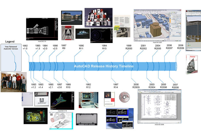
 Nova verzija AutoCAD-a 2010 će 24.marta.2009 biti objavljena. Autodesk Inc. nije čekao dugo da objavi novu definitivno bolju verziju od prethodnika 2009, tako da 2009-ka neće doživeti sudbinu 2005-ice. Šta donosi 2010? Pre svega bolje optimizovani format .dwg, eksportovanje crteža u PDF, plotovanje u 3D modelu i još puno toga. Demonstracija rada u AutoCAD-u 2010 se može preuzeti u video formatu .wmv na sledećim linkovima:
Geometric Constraints
Dimensional Constraints
Block Constraints
Block Tables
PDF Output
PDF Underlay
Mesh Modeling
Solid Modeling
3D Printing
More Tools
New and/or enhanced functions and some bug fixes.
![]() New file format “AutoCAD 2010″ and is likely to be used for AutoCAD 2011 and AutoCAD 2012. Last file format change was in AutoCAD 2007. The version number is 18.0 and the internal DWG and DXF version is AC1024. It is possible to save to earlier formats down to R14 DWG and R12 DXF.
New file format “AutoCAD 2010″ and is likely to be used for AutoCAD 2011 and AutoCAD 2012. Last file format change was in AutoCAD 2007. The version number is 18.0 and the internal DWG and DXF version is AC1024. It is possible to save to earlier formats down to R14 DWG and R12 DXF.
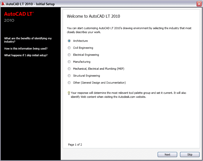
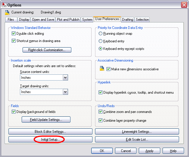
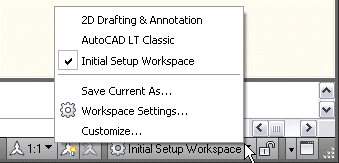
Initial Setup is displayed the first time you start AutoCAD 2010 and allow you to select the industry that most closely describes your work like Architecture or Civil Engineering for example. Depending on your choices the following will be set: the default settings of various AutoCAD functionality, including drawing templates, Autodesk® Seek filters, Autodesk Developer Network partners, the Unified Online Experience portal, and workspaces. If you later want to access Initial Setup it is available via Options>User Preferences.
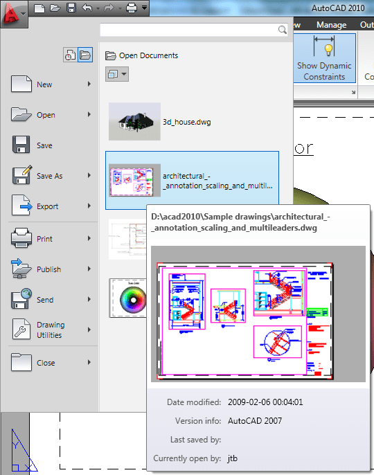
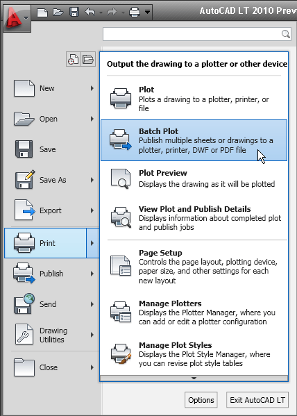
Application Menu has been changed a lot compared to AutoCAD 2009′s Menu Browser. There is no longer access to pull-down menus from here. Some name changes have been done. Publish command is known as Batch Plot and available via the Print menu. The Publish menu have access to Send to 3D Print Service and Archive but if you click directly on the Publish menu the publish command is launched.
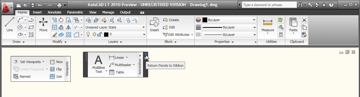
The ribbon has been updated. You can drag a ribbon panel off the ribbon to display it as a sticky panel. Sticky panels remain displayed, even when selecting a different tab, until you select the option to Return Panels to Ribbon.
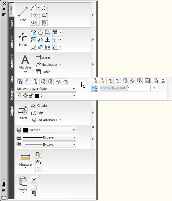
The vertical ribbon has been updated to show the tab names along the side. The panel titles are displayed by default and those with additional tools include slide-out panels. When resizing the vertical ribbon, buttons automatically flow to the next or previous row and other elements, such as slider bars, automatically shorten or lengthen.
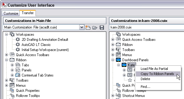
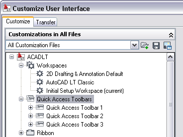
Custom dashboard panels can be converted to new ribbon panels using the Transfer tab in the Customize User Interface (CUI) Editor.
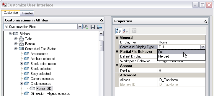
You can customize contextual ribbon tab states which control the display of ribbon tabs and panels based on either the type of object selected in the drawing window or the active command. You can display a ribbon tab that is assigned to a ribbon contextual tab state either on its own tab or with its panels merged onto each of the ribbon tabs in the current workspace. To add a ribbon tab, drag it from the Tabs node in the Customizations In pane to the contextual tab state. For example, if you want the Home tab to become active whenever you select an Arc object, drag the Home-2D ribbon tab to the Arc selected node under the Contextual Tab States. Select it and modify its display type to indicate if it should be displayed as its own tab or merged onto each ribbon tab.
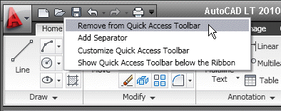
The Quick Access toolbar has been enhanced with more functionality and to ensure consistency with other Windows applications. The Undo and Redo tools include history support and the right-click menu includes new options that enable you to easily remove tools from the toolbar, add separators between tools, and display the Quick Access toolbar above or below the ribbon.
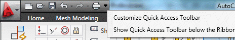
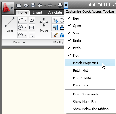
The Quick Access toolbar includes a new flyout menu, which displays a list of common tools that you can select to include in the Quick Access toolbar. The flyout menu provides easy access to additional tools using the Command List pane in the CUI Editor. Other options enable you to show the menu bar or display the Quick Access toolbar below the ribbon.
The Quick Access toolbar can be customized using the new Quick Access toolbars node in the CUI Editor. Multiple versions of the Quick Access toolbar can be created and added to different workspaces.
The New Features Workshop has been updated to include AutoCAD 2010 functionality.

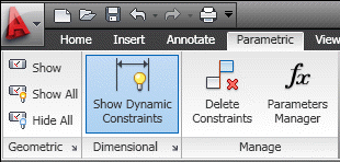
Parametric Drawing
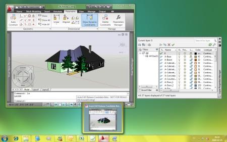
Parametric drawing functionality enables you to constraining drawing objects based on design intent. Geometric and dimensional constraints help ensure that specific relationships and measurements remain persistent even as objects are modified. The tools for creating and managing geometric and dimensional constraints are available on the Parametric ribbon tab, which is automatically displayed in the 2D Drafting and Annotation workspace.
Geometric constraints establish and maintain geometric relationships between objects, key points on objects, or between an object and the coordinate system. Pairs of key points on or between objects can also be constrained to be vertical or horizontal relative to the current coordinate system. For example, you could specify that two circles must always be concentric, that two lines are always parallel, or that one side of a rectangle is always horizontal.
Geometric relationships are defined with geometric constraints, located on the Geometric Panel of the Parametric tab of the ribbon, or with the GEOMCONSTRAINT command. When applying constraints, an icon appears next to the cursor to help you remember which constraint you selected.
When applying a constraint to points, a temporary marker identifies the closest valid point when rolling over an object. It generally corresponds with points that can be used as object snaps.
Whether selecting objects or points on objects to constrain, the order and pick location affects how the objects update: the second object selected updates to satisfy the constraint. After the constraint is applied, though, either object will update when the other is modified.
You can significantly automate the process of applying constraints using the AutoConstrain functionality, available on the Geometric panel of the Parametric tab. AutoConstrain automatically applies constraints to geometry that falls within specified tolerances. For example, applying AutoConstrain to a rectangle consisting of four lines generates the appropriate coincident, horizontal, parallel, and perpendicular constraints to maintain the rectangular shape through various edits. You can control which constraints are available, in what order they are applied, and a tolerance to determine whether constraints are automatically applied. These controls are available on the AutoConstrain tab of the Constraint Settings dialog box, which you can access from the Parametric tab or using the CONSTRAINTSETTINGS command.

Constraint bars show the constraints applied to an object. You can control the display of constraint bars using the CONSTRAINTBAR command or the Show, Show All, and Hide All options on the Geometric panel of the Parametric ribbon tab.
When constraint bars are displayed, you can pass the cursor over a constraint to view the constraint name and the objects that it affects.
You can further control the display of constraint bars on the Geometric tab of the Constraint Settings dialog box. Options include the ability to individually specify which types of constraints can be displayed in the constraint bar, apply transparency, and automatically show the constraint bars after applying constraints to selected objects regardless of the current constraint bar visibility setting.
Establishing Dimensional Relationships
Dimensional relationships put limits on measurements of geometry. For example, you could use a dimensional constraint to specify the radius of an arc, the length of a line, or that two parallel lines are always 15 mm apart. Changing the value of a dimensional constraint forces a change in geometry.
You can create dimensional constraints from the Dimensional panel of the Parametric tab or with the DIMCONSTRAINT command. There are seven types of dimensional constraints, similar to the different kinds of dimensions: Linear, Aligned, Horizontal, Vertical, Angular, Radial, and Diameter. In fact, you can use the DIMCONSTRAINT command to convert a traditional dimension to the corresponding dimensional constraint.
Dimensional constraints are assigned a name when created. The text of a dimensional constraint can display its name, value, or its name and expression (name = formula or equation or value). A “lock” icon appears next to all dimensional constraints to help you visually distinguish them from regular dimensions. By default, dimensional constraints are displayed with a fixed system style that is zoom-invariant—it stays the same size relative to the screen when you zoom in and out so it is always readable.
You can control the display of dimensional constraints, including the visibility of the lock icon, from the Dimensional tab of the Constraint Settings dialog box.
Easily edit a dimensional constraint using grips or by double-clicking on the dimension text to enter values. When you double-click, the constraint name and expression are automatically displayed regardless of the constraint format setting. You can enter just a value, or a name and value using the format name=value (for example, Width=1.5 or Width=Length/3). You can rename dimensional constraints, and use those names in formulas to set the values of other constraints. For example, if you have a rectangle with constraints named “length” and “width,” you could define the value of “width” as “length/3” to constrain the rectangle’s width to 1/3 of its length.
The Parameters Manager, available from the ribbon, enables you to manage dimensional parameters as well as create and manage user-defined parameters. You can provide a meaningful name for the parameter and then assign a numeric value or formula as its expression. A parameter’s expression can reference other parameters so that its value automatically updates when the other parameter values change.
Dimensional constraints can take one of two forms: Annotational or Dynamic. Both forms control geometry in the same way, but they differ in their appearance and they way they are managed.
Dynamic dimensional constraints are not intended to be used as plotted annotation and they have a predefined style that cannot be modified. The display height is controlled by the BPARAMETERSIZE system variable. The visibility of dynamic constraints can be controlled in a variety of ways. First, you can show or hide all dynamic constraints with two icons on the ribbon. Second, even if dynamic constraints are hidden, you can choose to display them when a constrained object is selected, by using the checkbox in the Constraint Settings dialog or the DYNCONSTRAINTMODE system variable. Finally, even if dynamic constraints are set to “Show All,” they will only appear if at least one of the constrained objects is visible (on a layer which is On and Thawed).
Annotational constraints look just like dimension objects, and are managed the same way. They have all the same properties as regular dimensions, including Style. Annotational constraints are intended to be used for plotted dimensional constraints.
You can specify which constraint form is applied by default using the CCONSTRAINTFORM system variable. Additionally, you can specify the constraint form when using the DIMCONSTRAINT command to create a new dimensional constraint. Even after you have created a dimensional constraint, you can easily change its constraint form using the Properties palette.
Dynamic Blocks
Dynamic Blocks supports geometric and dimensional constraints. They also support the ability to define a table of variations of the dynamic block.
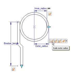
Constraint Parameters behave like dimensional constraints but also expose their name as a property for the block reference similar to dynamic block parameters. You can access constraint parameters from the Dimensional panel of the Block Editor tab in the ribbon or with the BCPARAMETER command. Constraint parameter options include Linear, Aligned, Horizontal, Vertical, Angular, Radial, and Diameter.
Construction geometry (BCONSTRUCTION command) enables you to convert existing objects to construction geometry. The construction geometry is visible in the Block Editor and can be constrained, but it does not display or plot in the block reference.
The Parameters Manager is available in the Block Editor. It lists user parameters, legacy action parameters, block constraint parameters, and attributes. Using the Parameters Manager, you can control whether or not a parameter is displayed in the Properties palette for a selected block reference and you can specify the order in which the parameters appear.
The Test Block tool (BTESTBLOCK command) enables you to test a block definition while authoring dynamic blocks. When you use this tool, AutoCAD opens a temporary window, similar to a drawing window, with the block reference already inserted. The Test Block Window is easily identifiable by the title bar, background color, and the contextual ribbon tab which includes a button to Close Test Block. When you close the test block, you’re automatically returned to the Block Editor.
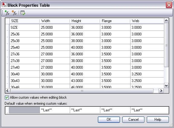
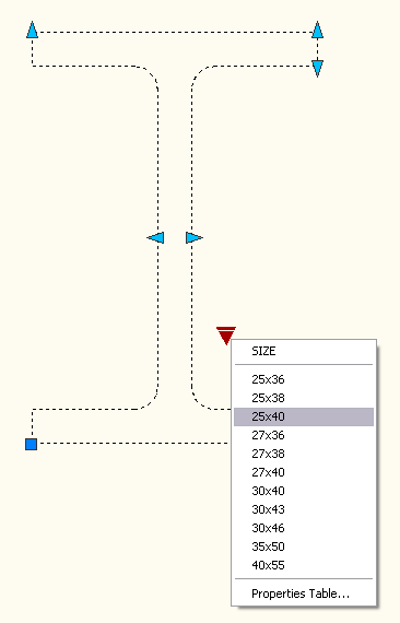
The Block Table tool is accessible from the Dimensional panel of the ribbon, or the BTABLE command, it displays the Block Properties Table where you can define different variations of a property set for the block reference. You can enter properties manually or copy and paste from a Microsoft® Office Excel® spreadsheet.
Action Bars
The display and positioning of Action objects in the Block Editor is enhanced to be consistent with Constraint bars. Action objects are no longer placed individually in the Block Editor; rather they are automatically grouped into Action bars based on the parameters with which they are associated. You can toggle between the new and old display styles by setting the BACTIONBARMODE system variable prior to entering the Block Editor. When viewing the block definition with Action bars turned on, you can quickly tell which actions are associated with which parameters and how many actions each of the parameters affects. You can also see which parameter has its “Chain actions” property enabled. If you roll over an action in an Action bar, both the associated parameter and affected geometry are highlighted.
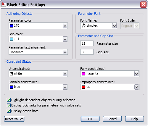
Block Editor Settings is launched with the command BESETTINGS and enables you to control all the settings for the Block Editor environment in one place. You can apply colors to objects based on their constraint status, making it easy to identify objects that are partially, fully, or over-constrained, or that have no constraints at all. The system variable BCONSTATUSMODE controls whether this shading is used.
Annotation Tools
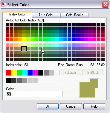
Color Selection – you can set layer colors and pick from the AutoCAD Color Index with ease. Access the Select Color dialog box directly from the Layer drop-down list by selecting on the layer color swatch. If the layer has a viewport color override, the color swatch has a white border. The new color you select applies to the appropriate viewport color override or global color.
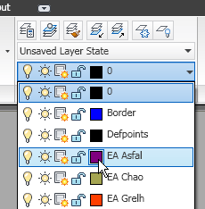
Behavior within the Select Color dialog box has also been improved. As you hover the cursor over a color swatch, the arrow cursor and a black border are displayed in addition to the traditional white border making it easier to see which swatch you are about to select.
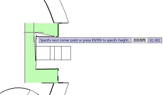
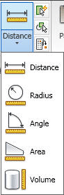 Measure Tools – The new MEASUREGEOM command enables you to measure the distance, radius, angle, area, or volume of a selected object or a sequence of points. You can access these tools from the Utilities panel of the Home ribbon tab. The default option is Distance. However, selecting a different measure tool will set it as the default for the remainder of the AutoCAD session or until a different tool is selected.
The Distance tool enables you to measure the distance between two points. AutoCAD visually displays the distance, delta x, delta y, and angle in the xy plane within the Drawing Editor. If you select the Multiple option, you can continue picking points and, with each pick, AutoCAD displays the cumulative distance. Other options within the Distance tool are similar to the Polyline command enabling you to switch between Line and Arc measuring modes.
You can use the Radius tool to display the radius of a selected arc or circle. The Angle tool measures the angle of a specified arc, circle, line, or vertex.
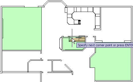
The Area tool enables you to specify points or select objects to display the included area. You can use the Add or Subtract options to determine cumulative areas. As you specify points or select objects, the included area dynamically highlights so that you can see what you’ve selected! Additional options within the Area tool enable you to switch between line and arc measuring tools so that you can easily measure curved spaces as well as polygonal.
You can use the Volume tool to specify boundary points with visual feedback similar to the Area option, and then specify a height to determine the volume. Additionally, you can display the volume of selected solids or regions.
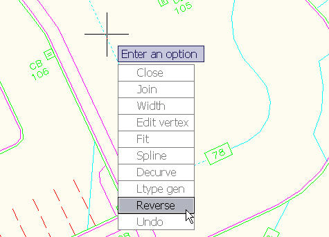
Reverse Tools – reverse the direction of lines, polylines, splines, and helixes.
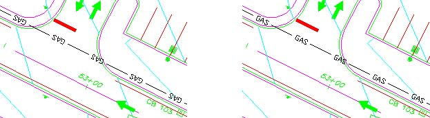
Reverse is also an option in the Pedit command.
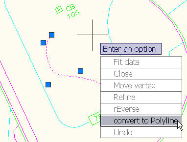
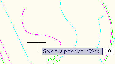
Spline Editing Tools – convert the SPLINE to a POLYLINE. If a SPLINE is selected in the PEDIT command, you get the option to convert it to a POLYLINE. Precision can be specified between 0 and 99 where 99 is the most accurate. If PEDITACCEPT is set to 1, the SPLINE is automatically converted. DELOBJ system variable is honored.
To further control the accuracy when converting splines to polylines, you can use the new PLINECONVERTMODE variable to specify the fit method. When PLINECONVERTMODE is set to 0, polylines are created with linear segments. When it’s set to 1 (the default), polylines are created with arc segments.
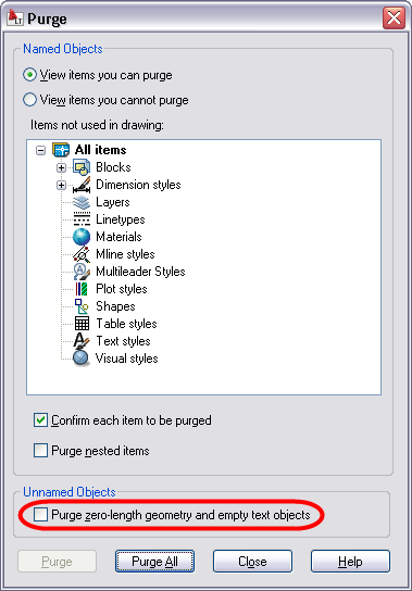
Purge Tools – The Purge dialog box has been updated to include an option for purging zero-length geometry and empty text objects. After performing the Purge operation, AutoCAD will report how many zero-length or empty text objects it purged. The same functionality is available at the Command line using the -PURGE command.
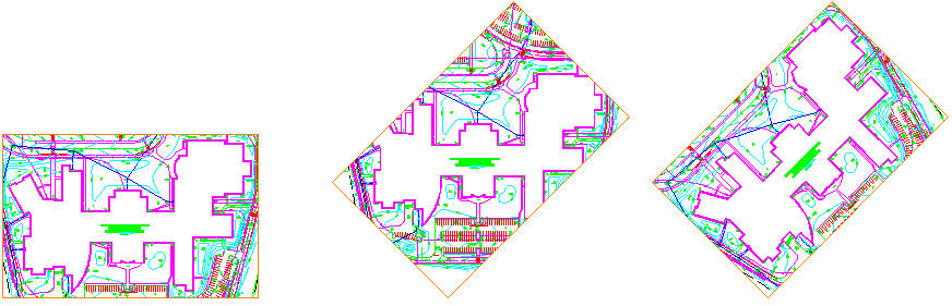
Viewport Rotation Tools – The new VPROTATEASSOC variable enables you to control the rotation of a view within a layout viewport. When you rotate the viewport with VPROTATEASSOC set to 1 (the default), the view will also rotate to maintain its orientation relevant to the viewport. When it’s set to 0, the view within the viewport will not rotate even though the viewport itself does.
External References – consolidated interface and increased flexibility for working with externally referenced file formats, including DWG, DWF, DGN, PDF, and Image files.
Attach externally referenced drawing files using geographic data. If both the host drawing and the external reference drawing have a geographic location, a new option in the External References dialog box enables you to locate the attached xref relative to the host drawing using Geographic Data. A similar option is available in the Insert dialog box.
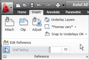
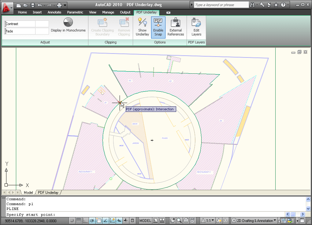
The Reference panel on the Insert tab of the ribbon provides tools for you to attach and modify externally referenced files. Use the Attach tool to select a DWG, DWF, DGN, PDF, or Image file and specify attachment options. Additional tools enable you to clip a selected reference, adjust its Fade, Contrast, and Brightness, control its layer visibility, display reference frames, snap to underlay geometry, and adjust xref fading.

When you select a reference file in the drawing, a relevant contextual tab is automatically displayed in the ribbon. For example, if you select a PDF underlay, the PDF Underlay tab is displayed providing you easy access to PDF underlay tools.
Easily edit the clip boundary of any reference using grips. You can even invert the clip with a simple click on the invert grip.
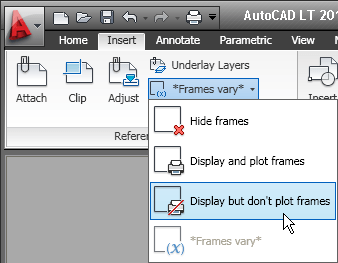
You can display the reference frame for each type of reference using its specific frame system variables such as DWFFRAME, DGNFRAME, and PDFFRAME. To quickly override these individual system variables, use the Frame tool (FRAME system variable) in the References panel of the Insert ribbon tab. You can hide frames, display and plot them, or display but not plot them.
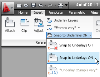
You can enable object snapping for geometry in underlay files. To control this behavior for specific reference types, use its individual system variables such as DWFOSNAP, DGNOSNAP, and PDFOSNAP. You can override these individual system variables using the Snap to Underlays tool (UOSNAP system variable) in the References panel of the Insert ribbon tab.
When you open a drawing that has unresolved references, a new tool helps identify the missing files.
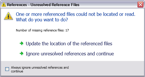
If you choose Update, AutoCAD opens the External References palette so you can repath the missing files. If you choose Ignore, the warning closes and takes no action. If you always want to ignore unresolved references, use the checkbox at the bottom to stop the warning from displaying again.
This is a great improvement over previous versions, when you had to manually search for missing references by checking the command line when opening a file, scouring the drawing for the text strings identifying unresolved references, or looking in the External References palette.
Sheet Sets - Sheet set functionality includes a variety of enhancements to increase productivity.
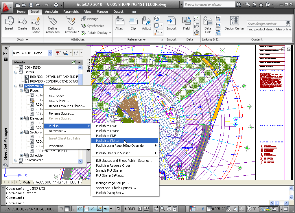
A new Sheet right-click menu option enables you to quickly specify whether a sheet should be included in the publish operation. To control the publish property of multiple sheets and even entire subsets, you can access the new Publish Sheets dialog box from the right-click menu by selecting the option to Edit Subset and Sheet Publish Settings.
The Subset Properties dialog box has a new look and feel, similar to the Sheet Set Properties and Sheet Properties dialog boxes. It includes a new control to specify if the subset should honor the sheets’ individual “Include for Publish” settings or if it, the entire subset, should be excluded from the publish operation. The Subset right-click menu includes similar options. An icon in the sheet list provides a visual indication of those subsets that are excluded from the Publish operation.
Sheet List Table functionality is more flexible. In addition to creating a sheet list table for the entire sheet set, you can now insert a sheet list table for individual subsets and even individual sheets. You can access this functionality from the right-click menu in the Sheet List table and a new tab in the Sheet List Table dialog box enables you to control the behavior of subsets and sheets. You can specify which sheets to include and which subsets to track so that you are prompted when new sheets are added to that subset.
Quick Views – The preview images for Quick View Layouts and Quick View Drawings have been enhanced to include a preview image of Model space in addition to the layout previews.
PDF Support – PDF support has been significantly enhanced. PDF publishing provides better visual quality with smaller file sizes, and you can even attach PDF files to a drawing as an underlay.
PDF output provides more flexibility and higher quality output than previously available. The default vector resolution has been increased from 400 to 600 dpi to produce precise lineweights at a reasonable file size. To further improve the visual quality of PDF output, TrueType fonts are exported as text rather than as graphics. This improves the visual quality of text and also enables highlighting, searching, and copying text within the PDF viewer. Additional improvements enable you to specify merge control, include layer information, and automatically preview the plotted PDF.
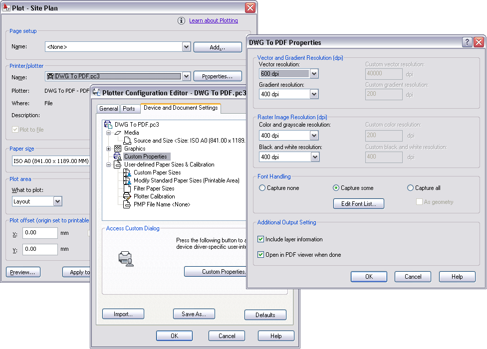
You can use the Plotter Configuration Editor to view and modify the PDF settings for plotted output. Select the DWG to PDF.pc3 plotter in the Plot dialog box and then choose Properties. The new Merge Control option is displayed under the Graphics node and the other options are accessible when you select Custom Properties.
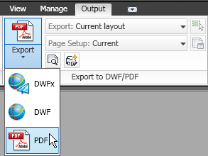
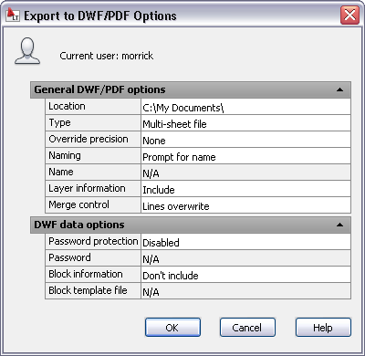
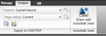
You can control many of the PDF output settings separately for exported, published, or plotted PDF files. A new Export to DWF/PDF panel on the Output ribbon tab provides access to the Export to DWF/PDF Options dialog box where you can specify a single- or multi-sheet PDF file, include layer information, and apply merge control. After applying the appropriate options, you can select PDF from the flyout tools.
In addition to the Plot and Export functionality, PDF support has been integrated into Sheet Sets and Publish. You can specify PDF output, including single- or multi-sheet, layer information, and merge control, in the Sheet Set Publish Options and the Publish Options dialog boxes.

You can attach a PDF file to an AutoCAD drawing as an underlay. You can work with PDF underlays in the same way you work with other external references including DWG, DWF, DGN, and Image files. You can even snap to key points on PDF geometry using familiar object snaps.
File Navigation dialogs such as Open and Save now support auto-complete when typing file names.

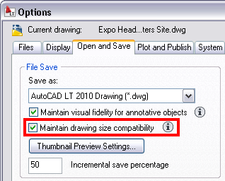
Object Size Limits
In previous versions of AutoCAD, no single object in an AutoCAD drawing could be larger than 256 MB. In AutoCAD 2010, the object size limit has been increased to at least 4 GB (depending on your system configuration), providing more flexibility. These large objects, however, are not backwards-compatible, so a new compatibility option has been added to the Open and Save tab of the Options dialog box. See the Maintain drawing size compatibility option.
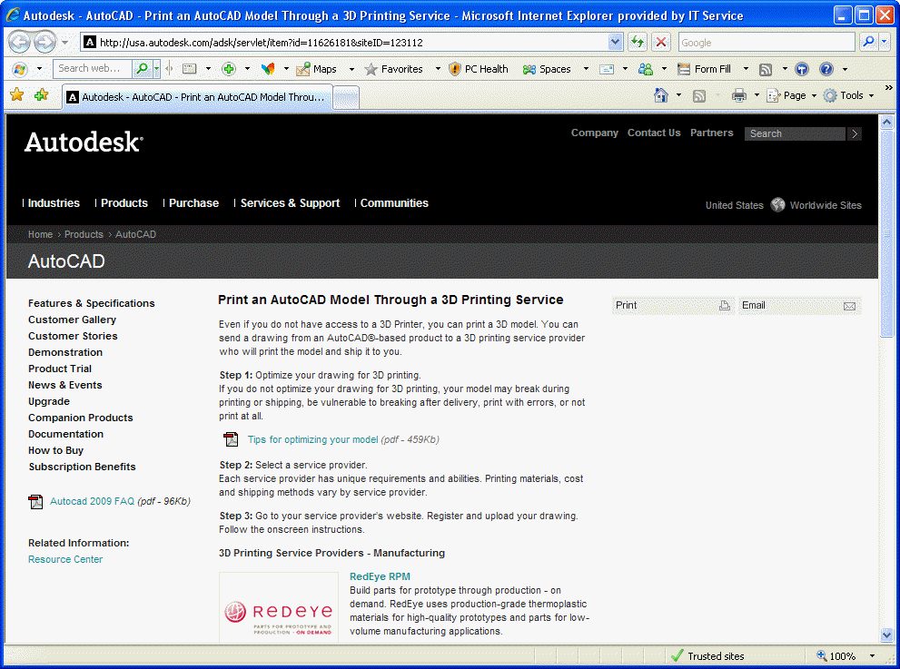
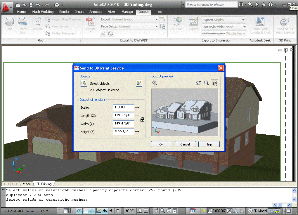
3D Printing – The 3D printing functionality enables you to output your 3D AutoCAD drawings directly to STL-supported 3D printing vendors through an internet connection. This utility will walk you through preparing your model, adjusting the scale, creating an STL file from your model, then downloading your STL file to a user-specified vendor for printing. The final 3D model will be printed then shipped to you within days.
You can prepare your model for 3D printing using the 3DPRINT command or selecting Send to 3D Print Service from the output tab. Select all solid objects you want to print. Once all objects are selected, select Return, which will display the Send to 3D Print Service dialog. Specify the scale of your model, then save the model to an STL format. Once saved, you are automatically directed to a location on Autodesk.com where you can select the 3D print vendor.
eTransmit – The eTransmit functionality has been enhanced to include a new option to “include unloaded file references.” When this option is enabled, all unloaded reference files are included in the transmittal set but will remain unloaded in the eTransmit package. The Archive functionality includes the same option to include unloaded file references and is enabled by default.
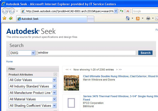
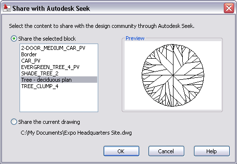
Autodesk Seek – Previously known as “Content Search,” Autodesk Seek is a more efficient online utility that allows users to quickly search product information and designs from the web and download the designs into AutoCAD. For example, if you were designing a home, and wanted to include pre-existing windows, you could look for product specifications and actual 2D and 3D design files on seek.autodesk.com. Search through the results for your desired window specifications, and then download the window file to incorporate it into your design.
Note: Currently Seek is focused on manufacturer-specific building products only, but is considering expanding to manufacturing products.
AutoCAD 2010 will also enable vendors to easily upload their designs to Seek using the Share with Autodesk Seek utility. This utility enables product vendors to move their product to the market quicker than ever before, so that AutoCAD designers can specify actual products in their designs.
After an initial setup process with Seek, users can download new designs whenever they wish using the Share with Autodesk Seek tool.
Conceptual and Free-Form Design
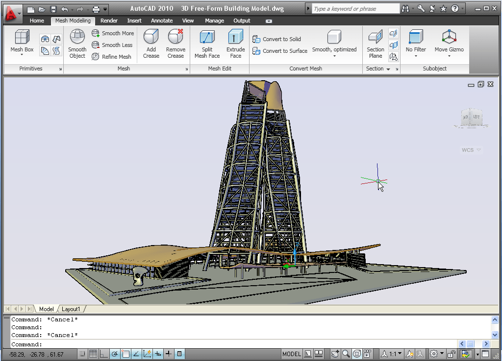
Smooth Mesh tools enable you to create 3D models that are free-form and flowing. The new Mesh Modeling ribbon tab provides easy access to the mesh creation and editing tools. A mesh object can be incrementally smoothed to create curved shapes, even when starting with a traditional primitive shape. The process of creating smooth mesh primitives is similar to creating their solid equivalents. You can adjust the smoothness level as you create the mesh by specifying the Settings option.
You can control the default tessellation divisions for each type of primitive using the Mesh Primitive options, which are accessible with the MESHPRIMITIVEOPTIONS command or from the 3D Modeling tab of the Options dialog box.
You can further control the behavior for converting objects such as solids and surfaces to mesh objects using the Mesh Tessellation Options dialog box, accessible with the MESHOPTIONS command or from the 3D Modeling tab of the Options dialog box.
You can split a mesh face by specifying two split points. You can then select and edit each new face, as well as the edges and vertices that they produce, using the CTRL key for subobject selection. Selecting individual subobjects enables you to further modify the shape of the mesh. In addition, you can apply different materials to individual faces.
Easily extrude a face in a mesh object using the Extrude Face tool on the Mesh Edit panel. Unlike extrusions performed on solid objects (which create a new solid object), mesh face extrusions extend and deform the mesh object without creating a new one.
After using the mesh creating and editing tools to create organic meshes, you can convert those that are watertight (no gaps) and not self-intersecting, to smooth or faceted solids. Additional tools enable you to convert meshes to smooth or faceted surfaces and you can control the smoothness of objects during the conversion process. These conversion tools are available in the Convert Mesh panel of the ribbon tab.
3D Scale Gizmo allow you to easily scale selected objects.
The 3D Move gizmo has been enhanced with longer axes, XYZ labels, and planar highlighting to make it easier for you to view and select the appropriate axis or plane. Save another step using the 3D Move gizmo by picking the constraint axis or plane and the base point in one operation. As you specify the second point, the 3D Move gizmo dynamically moves with the selected objects.
A new context menu, available when you right-click on a gizmo axis or plane, enables you to change the gizmo’s behavior. You can set the constraint to a different axis or plane, switch between the 3D Move, 3D Rotate, and 3D Scale gizmos, relocate the gizmo, and align it to the world UCS, current UCS, or an object face. You can further customize the location and orientation of the gizmo by manually specifying its origin, direction of the X-axis, and position of the XY plane.
In addition to using the right-click menu option to switch gizmos, you can press the space bar to cycle between them. If you want to change the gizmo that displays by default when you select an object, use the gizmo flyout on the ribbon.
Subobject Selection Filters restrict the selection of subobjects to faces, edges, or vertices. You can access these filters from the Subobject panel on the Home tab of the ribbon or from the right-click menu when no objects are selected. With the subobject selection filter set to vertex, for example, you can ensure that when you press CTRL and pick on the corner of an object, AutoCAD will select the vertex rather than the edge.
The Solid Editing panel of the Home tab includes tools to perform unions, subtractions, interferences, intersections, and imprinting. These tools, which were previously available only for solid objects, now work on surfaces as well.
CUIx File – the CUI file is replaced with the new CUIx file format. A CUIx file is a package file format that helps to improve performance when working with the CUI Editor. In addition to typical CUI information, a CUIx file contains the custom images used by the commands defined in the file.
Action Macros – User interface for Action Macros have been simplified for increased usability and efficiency.
The option to “Request User Input” has been renamed to “Pause for User Input” and the corresponding icon has been updated for consistency with the user icons in the Action Tree. The Action tree tooltips and playback behavior are more predictable and consistent when accepting default values by pressing the Enter key and when using dynamic input. In addition, the playback user messages have been streamlined for increased clarity.
A new command enables you to establish base points at specified locations in your action macro. You can access the new ACTBASEPOINT command as a button in the Action Recorder panel or as a right-click menu option in the Action Tree.
A new Action Macro Manager enables you to copy, rename, modify, and delete action macro files from a central location. An Options button in the lower left corner provides quick access to the Action Recorder settings on the Files tab of the Options dialog box. You can launch the Action Macro Manager from the Action Recorder panel in the ribbon as well as from the right-click menu (Action Recorder>Play>Manage Action Macros) when no objects are selected.

Online License Transfer (OLT) Utility that enables you to move stand-alone licenses between computers. It replaces the Portable License Utility (PLU) used in previous Autodesk product releases. You can access OLT functionality from the AutoCAD 2010>License Transfer Utility option in the Start menu.
From the License Transfer Utility, you can choose to export or import a license. Both options require you to log in to Autodesk. You can export a license as either private or public. A private license can be imported only by the person who exported it. A public license can be imported by any user running the same product and serial number.
![]()
Find and Replace - Optional zoom to each found text string. The result or highlighted objects can create a selection set.
Multileaders – Edit the properties of individual Multileader segments by using the CTRL key to select the segment and then accessing the Properties window. New grips at each corner of the leader text enable you to resize the text box in the same way you resize a simple mtext object.
Mleader styles have been enhanced to provide you with more control over the leader connections. On the Leader Structure tab, you can specify Vertical attachment in addition to the traditional Horizontal attachment. On the Content tab, when a Block multileader type is selected, you can specify a scale. The block scale is also displayed as a Multileader property in the Properties window. A new button on the Content tab provides direct access to the Text Style dialog box enabling you to create and modify text styles without exiting the Multileader Style dialog box.
The MLEADEREDIT command has been streamlined by eliminating the need for you to select an option to add or remove leader lines. It adds leaders by default until you select the option to remove leaders.
Mtext improvements include a default column mode of Dynamic with manual height. In addition, the corner grips on mtext objects are now consistent with the corner grips on table objects.
Spell checking – The Check Spelling dialog box has been updated to include an Undo button, which enables you to undo actions you made for the previous spelling mistake. In addition, the Select Objects button has been enhanced so that you can begin selecting objects to check without first having to choose the Select Objects option from the drop-down list.
Dimensions - Enhancements to dimension styles and properties provide more control over the display and placement of dimension text.
The Text tab of the Dimension Style dialog box has been updated with a new text placement option that enables you to position dimension text below the dimension line. You can control the direction of the text using the new View Direction option in which you can specify that the text be displayed from Left-to-Right or Right-to-Left. The Properties palette has been updated to include these new properties as well.
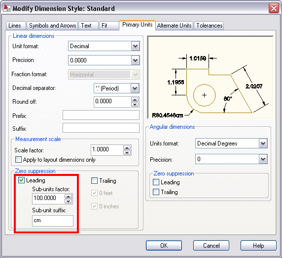
The Primary and Alternate Units tabs of the Dimension Style dialog box include new sub-unit controls for suppression of leading zeros. You can specify a sub-units factor and suffix. For example, if the unit is 1 meter, you could specify a sub-unit factor of 100 and sub-unit suffix of cm. In this case, when the dimension value is less than 1, such as .96, it displays as 96 cm instead of .96 m. The new sub-units properties are also included in the Properties palette.
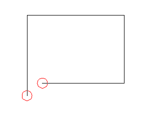
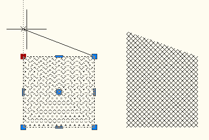
Hatch – When a hatch boundary area is not found, AutoCAD attempts to show you where the problem may have occurred. Red circles appear around endpoints near where any gap in geometry is estimated to be. More robust boundary detection.
Non-associative hatch objects can now be edited to change their shape.
AutoCAD 2010 running on Windows 7.
API news
New API for RibbonBar controls.
Overrule API is available in ObjectARX (C++) and .NET. Overruleed objects are like customized objects, rather than custom objects.
Freeform Modeling API enabling to work with the Sub-division mesh object.
Hardware and software requirements
SSE2 extended instruction set is supported and required so AutoCAD can use the power of modern CPUs better resulting in better speed.
| Description | Requirement |
| Operating system | 32bit: Windows Vista® Enterprise, Business, Ultimate, Home Premium (SP1), Windows® XP Professional, Home Edition (SP2 or later) 64bit: Windows Vista® Enterprise, Business, Ultimate, Home Premium (SP1), Windows® XP Professional x64 Edition (SP2 or later) For more information on Windows Vista versions please see http://www.microsoft.com/windowsvista/versions |
| Browser | Windows Internet Explorer® 7.0 or later |
| CPU type | 32bit: Windows Vista: Intel® Pentium® 4 or AMD Athlon® Dual Core, 3.0 GHz or higher with SSE2 technology Windows XP: Intel Pentium 4 or AMD Athlon Dual Core, 1.6 GHz or higher with SSE2 technology 64bit: AMD Athlon® 64 or Opteron® with SSE2 technology; Intel® Pentium® 4 or Xeon® with Intel EM64T support & SSE2 technology |
| Memory | Windows Vista: 2 GB RAM Windows XP: 2 GB RAM |
| Display resolution | 1024 x 768 display with True Color |
| Hard Disk | 32bit: 1 GB free disk space for installation 64bit: 1.5 GB free disk space for installation |
| Pointing Device | MS-Mouse compliant |
| Media (CD ROM vs. DVD) | Download and Installation from DVD or CD-ROM |
| 3D Modeling additional requirements | Intel Pentium 4 or AMD Athlon, 3.0 GHz or greater; Intel or AMD Dual Core, 2.0 GHz or greater 2 GB RAM or greater 2 GB free disk space available not including installation 1280 x 1024 32-bit color video display adapter (True Color) 128 MB or greater, Direct3D®-capable workstation class graphics card |
Preuzeto sa websajta JTB WORLD
.
Related articles
- No related posts found
 Registrovani korisnici će od danas moći da upgrade-uju svoju kopiju ePlusMenuCAD-a sa po veoma povoljnoj ceni od samo 40% od pune cene. Na ovaj način CsanyiGroup želi da izađe u susret svojim korisnicima koji žele da nastave da projektuju sa ePlusMenuCAD-om, i da pomažu razvoj programa. Postupak obnavljanja licence je identičan kao i regularna kupovina preko web strane za poručivanje, samo je polju za napomenu potrebno naglasiti da je u pitanju obnavljanje licence. Popust od 60% za licencu ePlusMenuCAD-a važi samo za registrovane korisnike programa, tj. korisnike koji su već kupili program.
Veze: ePlusMenuCAD™ | Poručivanje za pravna lica (firme) | Poručivanje za fizička lica
726 views

Na stranici Stručne knjige je omogućeno da ostavite svoj komentar na temu stručnih knjiga iz oblasti energetike, telekomunikacija, automatike…. i naravno AutoCAD-a. Takođe, korisnici mogu razmenjivati svoje knjige i mišljenja o postavljenim knjigama, kao i da predlože nove knjige ili kategorije koje bi se našle na ovoj web strani, ili da potražuju naslove kojih nema na sajtu.
Link: Stručne knjige
427 views
Postavljene su 2 nove web strane na kojima se nalaze stručne knjige RELEJI i GREJANJE. Knjiga THE RELAY BOOK sadrži 10-ak poglavlja o relejima, kontaktnim sistemima, mehaničkim komponentama itd., dok knjiga THE HEATING BOOK koju je izdao Danfoss sadrži skoro sve informacije i uputstva o sistemima grejanja, upute za projektovanje, formule za proračune itd. Sve knjige su besplatne za preuzimanje/download.
537 views
 Još jedna funkcija ePlusMenuCAD-a (v8.5.2) koja nije dostupna regularnim putem preko menija ili toolbar-a (samo sa komandne linije!) jeste funkcija za automatsko upisivanje brojeva nizu sa mogućnošću ubacivanja u krug i šestougaonik (‘NM’, ‘NMC’ i ‘NMP’). Funkcija se može koristiti veoma često u svakodnevnom radu gde je potrebno obeležavanje bilo čega sa brojevima u rastućem nizu, a da su pritom oznake stilizovane u krugu ili šestougaoniku. Sa ‘NM’ se ubacuju obični brojevi u rastućem nizu, dok se sa ‘NMC’ se oznake stilizuju sa krugom, a sa ‘NMP’ sa šestougaonikom. Nakon unošenja parametara na komandnoj liniji:
INCREMENT BY <1> – stepen povećanja rastućeg niza
START OR CONTINUE WITH NIMBER < zadni upamćeni broj > – broj od koga treba da počne niz
NUMBER LOCATION – potrebno je da kliknete i smestite svaku oznaku direktno na mesto gde Vam je potrebno (zgodno, zar ne!) Kasnije možete pomerati, kopirati ili menjati svaku oznaku pojedinačno.
Edvard Csanyi
350 views
Posle mesec dana rada, websajt csanyigroup.com je konačno dobio novi izgled. Fanovi koji često posećuju sajt i koji imaju email na Googlu su dobrodošli da se učlane na websajt i to preko servisa Google Friend Connect koji je postavljen u desnoj traci na strani sajta.
457 views
 Novogodišnji popust je produžen do 9. januara 2009! Poručite svoju kopiju programskog paketa ePlusMenuCAD sa novogodišnjim popustom od 15% na jednu i 20% na više licenci. Trenutna verzija v8.5.2 se može preuzeti ovde, i svako ko poruči program do 9. januara dobiće licencu sa navedenim popustom. Poručivanje se vrši na stranicama za fizička i pravna lica.
608 views
 Insertovanje energetskih i motornih izvoda, kao i bilo kog elementa iz iNteLLi Elements baze se svodi na prosti pick na sabirnicu i to na sredinu linije. Naime, sama sabirnica (plave boje) se sastoji iz 10 blokova koji odgovaraju 10 izvoda. U vertikali se nalazi u gornjem delu sabirnica, u sredini prostor za izvod ili element,
  zatim šina od nule N i šina od zaštitnog provodnika PE. Ispod svega ovoga se nalazi pripadajuća tabela sa podacima za konkretan izvod u čija se polja mogu upisivati podaci sa funkcijom MTB (tekst u tabeli) prostim pickom na donju liniju polja.
Prilikom insertovanja vrlo je korisno i važno da se se izvod postavi na sredinu sabirnice, jer će u suprotnom biti svi izvodi pomereni. Zato je važno da u Object Snap-u bude uključen Midpoint kako ne bi došlo do greške. Kada jednom unesete bilo koji element ili izvod u jednopolnoj šemi, za svaki sledeći izvod ili element NE MORATE picknuti na sabirnicu na Midpoint, već prosto pritisnite ENTER i biće automatski postavljen za mesto posle poslednjeg. To je moguće pošto je opcija Autoinsert stalno uključena (vidi na slici).
483 views
398 views
 Verzija 8.5.2 je objavljena. Dosta poboljšanja, mada ne vidljivih korisnicima je implementirano kako bi ova verzija bila dosta brža i stabilnija od prethodnih. Dakle, glavna novina je naravno adaptacija na AutoCAD 2009, mada ja lično očekujem da većina korisnika AutoCAD-a pređe tek polovinom sledeće godine na 2009-ku. Druga novina jeste da je sada moguće koristiti skoro sve simbole za jednopolne i šeme delovanja, tj. blokove iz baze iNteLLi Elements. U ranijim verzijama je to moglo, ali dosta komplikovanije, i svi blokovi su bili eksplodirani prilikom insertovanja. Sada je potrebno samo izvršiti funkciju MHI (make Mosaic Hibrid) i svi elementi osim energetskih i motornih izvoda (koji su ostali rezervisani za template Mosaic Design) se mogu nesmetano koristiti u bilo kojem crtežu iz baze (prečica ME). Treća velika novina jeste veliki popust od 20% koji se ostvaruje prvom kupovinom programa. Na ovaj način CsanyiGroup želi da svojim korisnicima izađe u susret i omogući im da jeftinije obnove svoju licencu.
Kako se približava Nova Godina, od 25. do 30. decembra će trajati veliki popusti od 15% na jednu i 20% na više licenci, dakle dobra prilika da se dođe do jeftinijeg ePlusMenuCAD-a.
Uskoro će biti objavljena i verzija koja će biti brendirana od strane Schneider Electric-a… više o tome uskoro!
477 views

Nova verzija v8.5.2 donosi ispravljenu grešku prilikom aktivacije programa, kao i veliko poboljšanje u Mosaic Design-u. Naime, radi se o tome da je sada moguće koristiti, tj. insertovati simbole iz baze iNteLLi Elements u bilo koji crtež, tj. jednopolnu šenu ili šemu delovanja u kojoj radite. Jedino su izuzeti celi energetski i motorni izvodi koji se mogu i dalje koristiti samo u okruženju template-a Mosaic Design-a. Korisnicima koji nisu već kupili licencu za ePlusMenuCAD, preporučuje se da upgrade-uju svoju kopiju, a korisnici koji poseduju svoju licencu mogu je obnoviti sa 20% popusta.
Download link: http://www.csanyigroup.com/?page_id=4
Novogodišnji popust počinje od 25-30. decembra!! Čitaj više…
589 views
U periodu od 25. do 30. decembra CsanyiGroup će svojim korisnicima ponuditi programski paket ePlusMenuCAD sa novogodišnjim popustom od 15% na jednu i 20% na više licenci. Trenutna verzija v8.5.2 se može preuzeti ovde, i svako ko poruči program od 25-30 decembra dobiće licencu sa navedenim popustom. Poručivanje se vrši na stranicama za fizička i pravna lica.
715 views
 Verzija 8.5.0 je objavljena! Posle dosta radova i izmena zbog adaptiranja na AutoCAD 2009, kao i puno drugih poboljšanja, krajem novembra je objavljena nova verzija.
Šta je poboljšano:
- ePlusMenuCAD se može instalirati na AutoCAD 2009. Najnovija verzija AutoCAD-a se može lako optimizovati za rad. Pročitaj više o tome ovde.
- Prozor Scale Factor-a (SF) se dosta brže otvara
- Sve funkcije, kako iz iz modula X-functions, tako i ostalog dela programa, su prevedene skroz na srpski/hrvatski i engleski jezik. Tamo gde to nije bilo moguće (zbog smisla), ostali su neki izrazi na engleskom.
- Unapređen Help
- Poboljšana funkcija iSave, koja sada čuva crtež sa uštedom do 80% od veličine crteža
- Otklonjena greška u Mosaic Design-u kod insertovanja celih energetskih i motornih izvoda kada nije uključen AUTOINSERT. Sada je stalno uključen.
- Otklonjena greška u Mosaic Design-u na listi elemenata JPS-Ostalo… gde su nedostajali elementi Kondenzatorska baterija, TN-S sistem oznake, TN-C-S sistem oznake, Oznake faza, Sifra kabla, Tablica za izvode i Izvod+N+PE (ZUDS).
- Otklonjena greška u proračunu pada napona u funkciji TPS.
- U funkciji InfoIt Database je podeljena baza simbola na dve baze, bazu simbola, tj. elemenata ePlusMenuCAD-a koja je ‘read only’ i bazu u koju korisnik može dodavati svoje simbole.
- Registracija, tj. proces aktivacije programa je poboljšan
Šta je novo:
- InfoIt PRO je dobio novu funkciju za otvaranje sačuvanog izveštaja, tj.  report-a (poziva se sa ‘REP’)
- Funkcija SaveToPage je zamenila funkciju SaveAs, tj. sada je moguće sačuvati sve listove jednopolne šeme i šeme delovanja u istom crtežu i to list do lista, kao što i većina projektanata praktikuje kod crtanja.
- Dodati su simboli fluroscentnih cevnih svetiljki snage 1x58W i 2x58W.
- Period besplatnog korišćenja programa je 30 dana
Instaliranje:
Ukoliko imate instaliranu neku raniju verziju ePlusMenuCAD-a, morate je deinstalirati, i to pokretanjem Uninstaller-a sa Start menija/Programs/ePlusMenuCAD u Windows-u. Ukoliko ste u InfoIt Database unosili definicije svojih blokova (kako bi bili izbrojani sa InfoIt PRO), savet je da iskopirate fajl InfoIt_database.mdb na neku drugu lokaciju na disku, jer će deinstalacijom biti izbrisana, i lako možete izgubiti sve definicije koje ste unosili. Fajl InfoIt Database se nalazi u folderu u kome je sam program instaliran, npr. c:\Program Files\ePlusMenuCAD\.
Jezik padajućeg menija i interfejsa:
Dostupni su srpski/hrvatski i engleski jezik. Prevod se odnosi na padajući meni, kao i skoro sve prozore koji se pojavljuju u programu. Potrebni su ljudi koji će prevesti program na ruski, nemački, italijanski i francuski jezik. Nagrada će biti jedna licenca ePlusMenuCAD-a po jeziku. Za više informacija o prevodu pišite na email office@csanyigroup.com.
Download:
Najnoviju verziju 8.5.0 ePlusMenuCAD-a, kao i Help možete preuzeti na stranici: ePlusMenuCAD
Sakrivene funkcije:
Prethodne verzije, kao i nova verzija 8.5.0 ima nekoliko sakrivenih funkcija koje će se vremenom objavljivati, i koje predstavljaju svojevrsno iznenađenje korisnicima ePlusMenuCAD-a. Sve skrivene funkcije će ostati sakrivene, tj. u narednim verzijama programa se neće pojavljivati u padajućem meniju ili toolbar-u, osim ako bude postojalo veliko interesovanje da se neka funkcija pojavi u padajućem meniju. Predlog možete poslati na email office@csanyigroup.com.
945 views
 Nova verzija v8.5.0 ePlusMenuCAD-a će definitivno podržavati AutoCAD 2009, tako da će projektanti koji koriste 2009-ku moći da opušteno instaliraju ePlusMenuCAD. Nakon dužeg perioda “igranja” sa AutoCAD-om 2009 i dalje stojim iza toga da je Autodesk Inc. sa novom verzijom svog mezimčeta potpuno promašio! Velika većina korisnika je nezadovoljna sa beskorisnim interfejsom kome treba par sekundi da počne da deluje… O ovome bi mogao da pišem satima… ali drugom prilikom….
Anyway, na mojoj Visti se najbolje pokazao upravo AutoCAD 2009, valjda zato što je jedina verzija potpuno prilagođena za Windows Vistu. AutoCAD 2009 se u par koraka može veoma dobro optimizovati tako da radi veoma brzo. Dakle, šta uraditi:
1) Isključiti ribon Kako? Ukucaj na komandnoj liniji RibbonClose i pritisni ENTER.
2) Uključi klasični meni kao u AutoCAD-u 2008/7/6 Kako? Ukucaj na komandnoj liniji MENUBAR, unesi 1 i pritisni ENTER.
Sada će AutoCAD 2009 izgleda kao ranije verzije, s’ tim da na Windows Visti raditi dosta brže. Na Windows XP-u takođe radi isto brže nego ranije verzije 2006-2008, ali ovo nije toliko izraženo kao u slučaju Windows Viste. Radove na ePmCAD-u v8.5.0 privodim kraju, i očekujem da do kraja meseca (NOV’08) završim sve i objavim konačnu verziju.
I dalje mi je potrebna neka dobra duša za prevođenje ePlusMenuCAD-a na italijanski, francuski, nemački i španski jezik. Nagrada za prevod biće besplatna verzija ePlusMenuCAD-a. Svoj zahtev možete poslati na office@csanyigroup.com.
Toliko za sada….
433 views
 Još jedna od funkcija koja nije dostupna u programu (regularnim putem) jeste funkcija SPEC. Tu funkciju sam napisao odavno i predstavlja ustvari preteče funkcije InfoIt PRO koja služi za generisanje tehničke specifikacije. Pokretanje je moguće samo sa komandne linije preko prečice ‘SPEC’.
Funkcija SPEC takođe koristi bazu InfoIt Database i uzima definicije blokova iz nje, ali se razlikuje od InfoIt u tome što se brže izvršava, ali je zato i siromašnija sa opcijama koje nudi. Kao rezultat se pojavljuje AutoCad prozor Text Window (poziva se sa F2) u kome su osnovni podaci iz crteža.
Ukoliko Vam je potrebno brzo izvršavanje tehničke specifikacije samo za pregled, onda je SPEC pogodna funkcija za Vas. Za sve druge potrebe u vezi generisanja tehničke specifikacije, preporuka je naravno, InfoIt PRO. U obe funkcije Vam je na raspolaganju export izveštaja u fajl. Ukoliko se ipak odlučite za InfoIt PRO, a pokrenuli ste SPEC, postoji dugme u donjem desnom uglu za pokretanje InfoIt PRO.
Pozdrav,
Edvard Csanyi
440 views
Uskoro će biti postavljena nova verzija v8.5 ePlusMenuCAD-a, u toku su pripreme i objavljivanje se očekuje do kraja novembra. Svi korisnici koji su kupili i registrovali svoju kopiju programa (prethodna verzije v8.4 build 1256), moći će slobodno da instaliraju i nastave da koriste program. Nova verzija doneće veću stabilnost u radu, kao i kompletan prevod celog programa na srpski, tj. engleski jezik. Biće još simbola dodato u kategoriji svetiljki i drugim kategorijama.
Ukoliko još niste kupili ePlusMenuCAD, to možete učiniti na stranicama za poručivanje:
- Za pravna lica
- Za fizička lica
Više informacija o samom programu (brošura, uputstvo), kao i njegovo preuzimanje (download) pogledajte ovde.
1,535 views
Kratkoročno: Napravi svoj blok, sačuvaj ga negde na svom disku, i u bazi blokova InfoIt Database upiši njegovo ime, tj. referencu kako bi bio podržan za brojanje.
Dugoročno: Pošalji blok, ili crtež simbola na email podrska@csanyigroup.com, i skoro 90% će se naći u sledećoj verziji ePlusMenuCAD-a.
Danas mi je jedan korisnik sugerisao na nedostatak legende za elemente “slabe struje”, i veoma sam mu zahvalan za to. Budući je program prilično razgranat, svaka sugestija je veoma dobrodošla, kako bi svaka sledeća verzija bila prilagođenija korisnicima.
1,097 views

Stranice Projektna dokumentacija, Stručni programi i Stručne knjige su update-ovane sa novim i korisnim sadržajem. Dokumentacija za projekat je dopunjena sa proračunima za kratki spoj, opštim proračunima za niskonaponske mreže, kao i jednim diplomskim radom na temu kompletnog el. projekta (samo tekst). Proteklih dana je bilo problema sa linkovima na ovoj stranici, to je sada ispravljeno i svi linkovi su sada dostupni. Stranica Stručni programi je dopunjena sa programskim paketima za proračune niskonaponske mreže, pada napona, fotometrijski proračun, programima za pregledanje dokumenata (DOC, XLS, SNP), kao i dodatak, tj. zamena za MS Access, koji je preporučen korisnicima koji koriste ePlusMenuCAD, a nemaju instaliran MS Access. Stranica Stručne knjige je najviše update-ovana, tj. dodato je dosta novih stručnih knjiga iz oblasti energetike, automatizacije, industrije i telekomunikacija. Izdvajamo celu seriju od 18 kvalitetnih knjiga “Basics of Energy and Automation: Introduction, Motors & Control and Power Distribution” Takođe, na ovoj strani su postavljene i knjige za korišćenje AutoCAD-a, kako za korisnike koji ga već koriste u svakodnevnom poslu i žele da unaprede svoje znanje, tako i za početnike. Izdvajamo knjige “AutoCAD tutorial (uputstvo za početnike, ver.2006-2008)” i “Introduction to AutoCAD 2008 2D/3D Design“. Za početnike AutoCAD-a postavljena je i stranica AutoCAD training koja sadrži osnove u 14 video lekcija od po 10-ak minuta u proseku po lekciji. Ovaj kurs je preuzet sa YOUTUBE servisa i izuzetno je popularan među internet korisnicima AutoCAD-a.
Linkovi: Projektna dokumentacija | Stručni programi | Stručne knjige | AutoCAD training
Edvard Csanyi
CsanyiGroup
1,232 views
 Instalirao sam ga pre par meseci i “na prvu loptu” sam se veoma razočarao. Samo čekanje da se prozor otvori me je “ubio” u pojam! Trebalo mu je više od 30 sekundi na mašini čije su perfomanse blizu kako klinci kažu “zveri” od kompjutera. No, nekako sam preživeo maratonsko otvaranje, sledeće iznenađenje je bilo interfejs i potpuno odsustvo menija!? Odmah sam provalio da je ceo korisnički interfejs dizajniran kao MS Office programi (Word, Excel…). Ovakav UI kod Windows Viste i MS Offica je zaista velika novina i osveženje, ali je Autodesk trebao da se drži svog interfejsa.
Naravno da sam probao da instaliram ePlusMenuCAD, i na moje veliko iznenađenje – instalirao se bez većih poteškoća. Naizgled je sve funkcionisalo kako treba, sve dok nisam testirao rad u Mosaic Design-u, i to insertovanje celih energetskih izvoda. AutoCAD se rušio konstanto i to uz poruku “fatal error”. Uz malo “čeprkanja” po internetu pronađem da je ukinuta jedna od funkcija koja je često korišćena u ePlusMenuCAD-u. To je bilo korisna informacija, ali mi i dalje nije bilo jasno zašto se AutoCAD ruši?!
Ko ne čita – ne zna! Na Autodesk-ovom sajtu lepo piše da je objavljen Service Pack 1 za AutoCAD 2009. Zakrpa za AutoCAD 2009 je naravno rešila problem rušenja prilikom insertovanja izvoda uz lepu poruku “function cancelled”.
Šta sledi dalje? Menjanje funkcija u Mosaic Design-u i pisanje dobrog dela koda ponovo. Sledeća verzija ePlusMenuCAD-a će sigurno podržavati AutoCAD 2009.
Do tada, mislim da ću koristiti AutoCAD 2008…
370 views
Mnogo bi pomoglo kada bi korisnici ostavili svoje komentare na funkcionalnost i rad u programu, kako bi se program razvijao u pravom smeru i prilagođavao potrebama korisnika tj. projektanata.
 Schneider Electric definitivno brendira ePlusMenuCAD!
Velika vest za CsanyiGroup i mnogobrojne korisnike ePlusMenuCAD-a stigla je danas 22.8.2008. Schneider Electric je odlučio da bi ovaj potez doprineo učvršćivanju svoje pozicije na tržištu vrhunskih proizvođača elektroopreme u Srbiji i regionu. Menadžment Schneider-a je prepoznao nesumnjivi kvalitet programa, i preduzeo prve korake ka brendiranju. ePlusMenuCAD će dobiti boje i obeležja Schneider-a u svim mogućim aspektima projektovanja električnih instalacija u najskorijem vremenskom periodu.
Naravno, mukotrpan rad na brendiranju tek predstoji, budući da je panorama proizvoda Schneider-a veoma velika., a vremena uvek malo! Korisnicima, tj. projektantima će biti višestruko olakšano projektovanje sa Schneider-ovom opremom, jer će u programu imati i svu opremu, kao i sve najnovije kataloge proizvoda po kategorijama.
![]()
![]()
Ono što mogu odmah da kažem jeste da će biti dosta novina u programu. Pritom mislim prvenstveno na podršku za skoro svu srednjenaponsku opremu, tj. postrojenja SM6, RM6, MCset, kao i niskonaponske ormane OKKEN, Himel i Prisma P, kao i dosta novih simbola i prekidača i zaštitnih uređaja, kao i funkcija u Mosaic Design-u. ePlusMenuCAD dosad nije imao podršku za SN opremu i NN ormane, ali će brendiranjem dobiti i to.
Ono što se zasad zna jeste da će brendiran ePlusMenuCAD biti moguće kupiti samo u Schneider Electric-u.
![]()
![]()
312 views
U narednom periodu će websajt CsanyiGroup biti redizajnirani osvežen sa novim idejama, boljom preglednošću i bržim učitavanjem strana. Sajt će biti dostupan iako se vrše izmene.
2,496 views
 Na stranici Stručne knjige postavljeno je 20-ak knjiga u PDF-u iz oblasti energetike i usko stručnih oblasti. Namenjene su svima kojima informacije iz ovih knjiga mogu da posluže. Ukoliko posedujete neku vrednu knjigu u elektronskoj formi, i želite da je podelite sa ostatkom sveta (čitaj inženjera!), možete je poslati na email: info@csanyigroup.com, i naći će se među ostalim knjigama na ovoj strani.
Sve knjige su freeware, tako da su potpuno legalno postavljene za download.
Edvard Csanyi
494 views
 Nisu sve funkcije dostupne u ePlusMenuCAD-u! Neke, kao što je ova su namenjene kao iznenađenje korisnicima. Naime, u pitanju je funkcija za efikasno i brzo zatvaranje svih crteža otvorenih u AutoCAD-u, i to sa ili bez čuvanja istih. Funkcija nosi naziv “Close All Drawings“, i pokreće se sa prečicom “CLO“.
Napisao sam je odavno za svoje potrebe, jer često imam otvoreno i po 10-ak crteža u kojima nešto testiram, pa sam sebi olakšao život na ovaj način. Sada delim ovu funkciju sa Vama! U narednoj verziji će biti implementirana u meniju i nekom od toolbarova.
Pozdrav,
Edvard Csanyi
912 views

Nova verzija v8.43 build 1256 je konačno ugledala svetlost dana! Pored dosta novina, puno funkcija je redizajnirano i poboljšano, tako da je sam program sada kompletan i kao rešenje za projektante elekričnih instalacija – zaokružena celina.
Stvari koje su NOVE u programu:
- Help sa detaljnim opisima svih poglavlja i funkcija u programu (WEBHelp)
- Dodati simboli transformatora (pogledi odozgo i sa strane):
- Suvi transformator
- 630kVA 10-20/0.4kV
- 1000kVA 10-20/0.4kV
- 1600kVA 10-20/0.4kV
- 2000kVA 10-20/0.4kV
- 2500kVA 10-20/0.4kV
- Uljni transformator SA konzervatorom:
- 630kVA 10-20/0.4kV
- 1000kVA 10-20/0.4kV
- 1600kVA 10-20/0.4kV
- 2000kVA 10-20/0.4kV
- 2500kVA 10-20/0.4kV
- 3200kVA 10-20/0.4kV
- Uljni transformator BEZ konzervatora:
- 630kVA 10-20/0.4kV
- 1000kVA 10-20/0.4kV
- 1600kVA 10-20/0.4kV
- 2000kVA 10-20/0.4kV
- 2500kVA 10-20/0.4kV
- 3200kVA 10-20/0.4kV
- Suvi transformator
- Dodati simboli za telekomunikacione i signalne sisteme:
- Kontrola pristupa:
- Čitač kartica
- Čitač koda
- Mehanička vrata/prolaz
- Optički + akustični indikator
- Semafor
- Rotaciono svetlo
- …
- TV/Radio instalacije
- Antena TV+R
- Sabirač signala (antenski)
- Razdelnik signala (antenski)
- Yagi antena – 3 elementa
- Parabolična antena
- …
- Telefonska/Interfonska instalacija
- Pozivna kutija
- SLP-Telefon
- Telefon sa video displejom
- …
- Video nadzor – CCTV instalacija
- CCTV-monitor
- CCTV-multiplexer
- CCTV-quadrator
- CCTV-videomatrix
- …
- Protiv-provalna instalacija
- Kombinovani senzor (IR+staklo)
- 2x senzor u plafonu (IR+mikrotalasni)
- Alarm za uzbunu
- Bežični prijemnik – alarm za uzbunu
- IR bariera
- IR senzor pokreta (fan antimasking)
- Shock sensor
- Signalno svetlo (paralelni opt. indikator)
- …
- Časovnik
- Električni sat, dvostrani
- SLP-sat
- …
- Protiv-požarna instalacija
- Požarni alarm – automatski
- Požarni alarm – linearni – pasivna refleksija
- Prijemnik-linearni požarni alarm
- Transmiter – linearni požarni alarm
- Detektor požara (u sigurnosnim alarmnim sistemima)
- Detektor lomljenja stakla (antimasking)
- Senzor lomljenja stakla (antimasking)
- …
- Gas
- Detektor curenja gasa
- Audio-Video sistemi
- Kontrolna tabla sa mikrofonom za emitovanje (6 zona)
- Centrala za lokalno emitovanje
- SLP-bežični mikrofon
- SLP-regulator jačine zvuka
- Premotavač trake – biskop
- Projektor za bioskop
- …
- Instalacija ozvučenja
- SLP-zvučnik
- Zvučnik za dvorane
- Ostalo (wireless…)
- Bežični prijemnik
- Bežični telefon
- Bežični transmiter
- Piezoelektrični senzor
- Kasa
- Izvor napajanja
- SLP-električni gatekeeper
- …
- Kontrola pristupa:
- Novi template-i za Mosaic Design
- Tropolna šema dovodnog polja sa mikroprocesorskom zaštitom u 0.4kV postrojenju
- Tropolna šema kondenzatorskog polja 0.4kV postrojenja
- Šema delovanja merne ćelije u 10kV postrojenju
Poboljšanja:
- Poboljšana funkcija u Mosaic Design-u za automatsko insertovanje energetskih i motornih izvoda
- Kompletan meni je redizajniran
- Poboljšan interfejs za reigistraciju i aktivaciju programa
- …
Novu verziju ePlusMenuCAD-a možete preuzeti ili pročitati više o tome na sledećim stranicama:
819 views
ePlusMenuCAD se može instalirati na onoliko AutoCAD-a koliko ih trenutno podržava, a to su:
- AutoCAD 2006
- AutoCAD 2007
- AutoCAD 2008
Instaliranje ePlusMenuCAD-a se u Windows-u radi samo jedanput, dok je za svaku verziju AutoCAD-a potrebno da ga posebno instalirate. Jednom kada kupite licencu za program, važi Vam zauvek, i to za svaku verziju AutoCAD-a koju program podržava (gore navedene verzije).
Dakle, pošto je bilo puno pitanja u vezi instaliranja, odgovor je sledeći:
ePlusMenuCAD može biti instaliran na nekoliko (3) AutoCAD verzija na jednom računaru.
289 views
![]() WEBHelp (Help) za ePlusMenuCAD™ je konačno završen i postavljen kao FINALNA 1.03 verzija. Opisane su nove funkcije i poglavlja koja se nalaze u novoj verziji ePlusMenuCAD™-a v8.43 build 1256, koja će biti postavljena za download za neki dan. Nemojte da Vas zbuni, neka poglavlja u WEBHelp-u nisu ista ili ih uopšte nema u tekućoj verziji (v8.4 build 1010), i ona su implemntirana u sledećoj verziji ePlusMenuCAD™.-a.
WEBHelp (Help) za ePlusMenuCAD™ je konačno završen i postavljen kao FINALNA 1.03 verzija. Opisane su nove funkcije i poglavlja koja se nalaze u novoj verziji ePlusMenuCAD™-a v8.43 build 1256, koja će biti postavljena za download za neki dan. Nemojte da Vas zbuni, neka poglavlja u WEBHelp-u nisu ista ili ih uopšte nema u tekućoj verziji (v8.4 build 1010), i ona su implemntirana u sledećoj verziji ePlusMenuCAD™.-a.
Nova verzija ePlusMenuCAD™-a će sem Help-a imati veoma dosta poboljšanja i implementiranih novih stvari.
Linkovi:
WEBHelp 1.03 final online read – Go!
Help v1.0.3 final – Download (2.34 MB) (downloaded 533 times)
492 views
 Help za ePlusMenuCAD je postavljen za download. Help je još uvek u beta fazi, ali je 95% upotrebljiv. Dok ne bude skroz gotov i integrisan u novu verziju ePlusMenuCAD-a (v8.41 build 1256) korisnici ga mogu preuzeti na Download strani, kao i na ePlusMenuCAD strani.
U Helpu ćete videti dosta stvari kojih nema u tekućoj verziji ePlusMenuCAD-a. Nemojte se zbuniti, Help je rađen i radi se za novu verziju programa. Help, kao i nova verzija ePlusMenuCAD-a biće postavljena za 3-4 dana.
Direktan link za download Help-a:
509 views
Vrlo često se dešava da projektanti menjaju izgled već postojećeg bloka na crtežu. To nije neki naročiti problem, ali ako tih blokova ima puno, kao recimo npr. svetiljki na crtežu. Šta raditi onda?
Komanda REFEDIT može da Vam reši ovakav problem za 3 sekunde. U pitanju je regularna AutoCAD komanda koja menja referencu u ovom slučaju bloka.
Kada uđete u prozor REFEDIT-a izmenite šta želite i potvrdite izmene na “Save reference Edits“. Svi blokovi sa istim nazivom su na osnovu ove izmene jednog bloka izmenjeni. Na ovaj način mogu se menjati bilo koji blokovi na crtežu.
Ovo se može primeniti na sve blokove koji su podržani u ePlusMenuCAD-u.
335 views
 ePlusMenuCAD WEBHelp je postavljen u beta izdanju. Nakon puno zahteva za bilo kakvim oblikom help-a, odlučio sam se da postavim ovaj oblik kako bi pomogao korisnicima ePlusMenuCAD-a. Help će biti dovršen u najskorijem vremenskom periodu, i biće integrisan u novoj verziji ePlusMenuCAD-a, zajedno sa dosta drugih novina i poboljšanja.
WEBHelp-u možete pristupiti ovde.
Ukoliko želite da neki deo bude posebno ili bolje opisan u WEBHelp-u rado ću Vam izaći u susret. Opišite koji deo programa želite da bude bolje opisan i pošaljite na email: podrska@csanyigroup.com
Edvard Csanyi
462 views
Uskoro će biti postavljena update-ovana verzija ePlusMenuCAD-a. Od novih stvari izdvajamo:
- Potpuna podrška za TKS telekomunikacione sisteme – “slabu struju” u vidu 100-ak blokova koji pokrivaju sve aspekte projektovanja slabe struje.
- Help za ePlusMenuCAD – kompletan i detaljan
- Mosaic Design – više template-a
- …
1,813 views
 Prilozi u projektnoj dokumentaciji su postavljeni za download i nalaze se na strani Projektna dokumentacija. Ovi dokumenti su stalno prisutni u projektnoj dokumentaciji, nije loše da svi stoje na jednom mestu. Od svih dokumenata (koji nisu vezani za konkretan projekat, npr. projektni zadatak… – a potrebne su male izmene) izdvajamo:
- Opšti i tehnički uslovi
- Tehnički proračuni:
- struja kratkih spojeva u mreži 10 kV
- struja kratkog spoja na sabirnicama glavnog razvoda 0,4 kV
- minimalnog preseka kablova 10 kV prema nominalnoj potrošnji i termičkom naprezanju u kratkom spoju
- … više na stranici Projektna dokumentacija
- Spisak propisa i preporuka
- Zaštita na radu
Uskoro će biti postavljeno više dokumenata. Takođe će biti postavljeno i 10-ak template-a Mosaic Design crteža.
Ukoliko želite da vidite kako bi izgledao npr. vaš glavni razvodni orman u izdanju Mosaic Design – popunite formu i “zakačite” svoju jednopolnu/šemu delovanja, i dobićete ubrzo nazad istu šemu prerađenu u Mosaic Design-u. Ako biste voleli da Vaš template razvodnog ormana bude integrisan u sledećoj verziji ePlusMenuCAD v8.5 popunite formu (ovde), navedite da je šema namenjena za sledeću verziju ePlusMenuCAD-a.
5,749 views
![]() Principi IEC standarda IEC 60364 i 60479-1 predstavljaju osnove na kome počiva većina električnih standarda u svetu. Dole su prikazani oni najvažniji. Više o ostalim standardima – klikni ovde.
Principi IEC standarda IEC 60364 i 60479-1 predstavljaju osnove na kome počiva većina električnih standarda u svetu. Dole su prikazani oni najvažniji. Više o ostalim standardima – klikni ovde.
IEC 60364-1 Electrical installations of buildings – Fundamental principles
IEC 60364-4-41 Electrical installations of buildings – Protection for safety – Protection against electric shock
IEC 60364-4-42 Electrical installations of buildings – Protection for safety – Protection against thermal effects
IEC 60364-4-43 Electrical installations of buildings – Protection for safety – Protection against overcurrent
IEC 60364-4-44 Electrical installations of buildings – Protection for safety – Protection against electromagnetic and voltage disrurbance
IEC 60364-5-51 Electrical installations of buildings – Selection and erection of electrical equipment – Common rules
IEC 60364-5-52 Electrical installations of buildings – Selection and erection of electrical equipment – Wiring systems
IEC 60364-5-53 Electrical installations of buildings – Selection and erection of electrical equipment – Isolation, switching and control
IEC 60364-5-54 Electrical installations of buildings – Selection and erection of electrical equipment – Earthing arrangements
IEC 60364-5-55 Electrical installations of buildings – Selection and erection of electrical equipment – Other equipments
IEC 60364-6-61 Electrical installations of buildings – Verification and testing – Initial verification
IEC 60364-7-701 Electrical installations of buildings – Requirements for special installations or locations – Locations containing a bath tub or shower basin
IEC 60364-7-702 Electrical installations of buildings – Requirements for special installations or locations – Swimming pools and other basins
IEC 60364-7-703 Electrical installations of buildings – Requirements for special installations or locations – Locations containing sauna heaters
IEC 60364-7-704 Electrical installations of buildings – Requirements for special installations or locations – Construction and demolition site installations
IEC 60364-7-705 Electrical installations of buildings – Requirements for special installations or locations – Electrical installations of agricultural and horticultural
premises
IEC 60364-7-706 Electrical installations of buildings – Requirements for special installations or locations – Restrictive conducting locations
IEC 60364-7-707 Electrical installations of buildings – Requirements for special installations or locations – Earthing requirements for the installation of data
processing equipment
IEC 60364-7-708 Electrical installations of buildings – Requirements for special installations or locations – Electrical installations in caravan parks and caravans
IEC 60364-7-709 Electrical installations of buildings – Requirements for special installations or locations – Marinas and pleasure craft
IEC 60364-7-710 Electrical installations of buildings – Requirements for special installations or locations – Medical locations
IEC 60364-7-711 Electrical installations of buildings – Requirements for special installations or locations – Exhibitions, shows and stands
IEC 60364-7-712 Electrical installations of buildings – Requirements for special installations or locations – Solar photovoltaic (PV) power supply systems
IEC 60364-7-713 Electrical installations of buildings – Requirements for special installations or locations – Furniture
IEC 60364-7-714 Electrical installations of buildings – Requirements for special installations or locations – External lighting installations
IEC 60364-7-715 Electrical installations of buildings – Requirements for special installations or locations – Extra-low-voltage lighting installations
IEC 60364-7-717 Electrical installations of buildings – Requirements for special installations or locations – Mobile or transportable units
IEC 60364-7-740 Electrical installations of buildings – Requirements for special installations or locations – Temporary electrical installations for structures,
amusement devices and booths at fairgrounds, amusement parks and circuses
IEC 60427 High-voltage alternating current circuit-breakers
IEC 60439-1 Low-voltage switchgear and controlgear assemblies – Type-tested and partially type-tested assemblies
IEC 60439-2 Low-voltage switchgear and controlgear assemblies – Particular requirements for busbar trunking systems (busways)
IEC 60439-3 Low-voltage switchgear and controlgear assemblies – Particular requirements for low-voltage switchgear and controlgear assemblies intended to
be installed in places where unskilled persons have access for their use – Distribution boards
IEC 60439-4 Low-voltage switchgear and controlgear assemblies – Particular requirements for assemblies for construction sites (ACS)
Read more


